
ABB Robotics
Technical reference manual
RAPID Instructions, Functions and Data types
© Copyright 2004-2010 ABB. All rights reserved.
Technical reference manual
RAPID Instructions, Functions and Data types
RobotWare 5.13
Document ID: 3HAC 16581-1
Revision: J
© Copyright 2004-2010 ABB. All rights reserved.
The information in this manual is subject to change without notice and should not be
construed as a commitment by ABB. ABB assumes no responsibility for any errors that
may appear in this manual.
Except as may be expressly stated anywhere in this manual, nothing herein shall be
construed as any kind of guarantee or warranty by ABB for losses, damages to persons
or property, fitness for a specific purpose or the like.
In no event shall ABB be liable for incidental or consequential damages arising from
use of this manual and products described herein.
This manual and parts thereof must not be reproduced or copied without ABB's written
permission, and contents thereof must not be imparted to a third party nor be used for
any unauthorized purpose. Contravention will be prosecuted.
Additional copies of this manual may be obtained from ABB at its then current charge.
© Copyright 2004-2010 ABB All rights reserved.
ABB AB
Robotics Products
SE-721 68 Västerås
Sweden

Table of Contents
33HAC 16581-1 Revision: J
© Copyright 2004-2010 ABB. All rights reserved.
Overview . . . . . . . . . . . . . . . . . . . . . . . . . . . . . . . . . . . . . . . . . . . . . . . . . . . . . . . . . . . . . . . . . . . . . . . . . . . . 13
1 Instructions 15
1.1 AccSet - Reduces the acceleration . . . . . . . . . . . . . . . . . . . . . . . . . . . . . . . . . . . . . . . . . . . . . . . . . . . . . . 15
1.2 ActUnit - Activates a mechanical unit . . . . . . . . . . . . . . . . . . . . . . . . . . . . . . . . . . . . . . . . . . . . . . . . . . . 17
1.3 Add - Adds a numeric value. . . . . . . . . . . . . . . . . . . . . . . . . . . . . . . . . . . . . . . . . . . . . . . . . . . . . . . . . . . 19
1.4 AliasIO - Define I/O signal with alias name . . . . . . . . . . . . . . . . . . . . . . . . . . . . . . . . . . . . . . . . . . . . . . 21
1.5 ":=" - Assigns a value . . . . . . . . . . . . . . . . . . . . . . . . . . . . . . . . . . . . . . . . . . . . . . . . . . . . . . . . . . . . . . . . 24
1.6 BitClear - Clear a specified bit in a byte data. . . . . . . . . . . . . . . . . . . . . . . . . . . . . . . . . . . . . . . . . . . . . . 26
1.7 BitSet - Set a specified bit in a byte data . . . . . . . . . . . . . . . . . . . . . . . . . . . . . . . . . . . . . . . . . . . . . . . . . 28
1.8 BookErrNo - Book a RAPID system error number . . . . . . . . . . . . . . . . . . . . . . . . . . . . . . . . . . . . . . . . . 30
1.9 Break - Break program execution. . . . . . . . . . . . . . . . . . . . . . . . . . . . . . . . . . . . . . . . . . . . . . . . . . . . . . . 32
1.10 CallByVar - Call a procedure by a variable . . . . . . . . . . . . . . . . . . . . . . . . . . . . . . . . . . . . . . . . . . . . . . 33
1.11 CancelLoad - Cancel loading of a module . . . . . . . . . . . . . . . . . . . . . . . . . . . . . . . . . . . . . . . . . . . . . . . 35
1.12 CheckProgRef - Check program references. . . . . . . . . . . . . . . . . . . . . . . . . . . . . . . . . . . . . . . . . . . . . . 37
1.13 CirPathMode - Tool reorientation during circle path. . . . . . . . . . . . . . . . . . . . . . . . . . . . . . . . . . . . . . . 38
1.14 Clear - Clears the value . . . . . . . . . . . . . . . . . . . . . . . . . . . . . . . . . . . . . . . . . . . . . . . . . . . . . . . . . . . . . 43
1.15 ClearIOBuff - Clear input buffer of a serial channel . . . . . . . . . . . . . . . . . . . . . . . . . . . . . . . . . . . . . . . 44
1.16 ClearPath - Clear current path . . . . . . . . . . . . . . . . . . . . . . . . . . . . . . . . . . . . . . . . . . . . . . . . . . . . . . . . 45
1.17 ClearRawBytes - Clear the contents of rawbytes data . . . . . . . . . . . . . . . . . . . . . . . . . . . . . . . . . . . . . . 49
1.18 ClkReset - Resets a clock used for timing . . . . . . . . . . . . . . . . . . . . . . . . . . . . . . . . . . . . . . . . . . . . . . . 51
1.19 ClkStart - Starts a clock used for timing. . . . . . . . . . . . . . . . . . . . . . . . . . . . . . . . . . . . . . . . . . . . . . . . . 52
1.20 ClkStop - Stops a clock used for timing. . . . . . . . . . . . . . . . . . . . . . . . . . . . . . . . . . . . . . . . . . . . . . . . . 54
1.21 Close - Closes a file or serial channel. . . . . . . . . . . . . . . . . . . . . . . . . . . . . . . . . . . . . . . . . . . . . . . . . . . 55
1.22 CloseDir - Close a directory. . . . . . . . . . . . . . . . . . . . . . . . . . . . . . . . . . . . . . . . . . . . . . . . . . . . . . . . . . 56
1.23 Comment - Comment . . . . . . . . . . . . . . . . . . . . . . . . . . . . . . . . . . . . . . . . . . . . . . . . . . . . . . . . . . . . . . . 57
1.24 Compact IF - If a condition is met, then... (one instruction) . . . . . . . . . . . . . . . . . . . . . . . . . . . . . . . . . 58
1.25 ConfJ - Controls the configuration during joint movement . . . . . . . . . . . . . . . . . . . . . . . . . . . . . . . . . .59
1.26 ConfL - Monitors the configuration during linear movement . . . . . . . . . . . . . . . . . . . . . . . . . . . . . . . . 61
1.27 CONNECT - Connects an interrupt to a trap routine . . . . . . . . . . . . . . . . . . . . . . . . . . . . . . . . . . . . . . 63
1.28 CopyFile - Copy a file . . . . . . . . . . . . . . . . . . . . . . . . . . . . . . . . . . . . . . . . . . . . . . . . . . . . . . . . . . . . . . 65
1.29 CopyRawBytes - Copy the contents of rawbytes data . . . . . . . . . . . . . . . . . . . . . . . . . . . . . . . . . . . . . .67
1.30 CorrClear - Removes all correction generators . . . . . . . . . . . . . . . . . . . . . . . . . . . . . . . . . . . . . . . . . . . 70
1.31 CorrCon - Connects to a correction generator . . . . . . . . . . . . . . . . . . . . . . . . . . . . . . . . . . . . . . . . . . . . 71
1.32 CorrDiscon - Disconnects from a correction generator . . . . . . . . . . . . . . . . . . . . . . . . . . . . . . . . . . . . . 76
1.33 CorrWrite - Writes to a correction generator . . . . . . . . . . . . . . . . . . . . . . . . . . . . . . . . . . . . . . . . . . . . . 77
1.34 DeactUnit - Deactivates a mechanical unit. . . . . . . . . . . . . . . . . . . . . . . . . . . . . . . . . . . . . . . . . . . . . . . 79
1.35 Decr - Decrements by 1 . . . . . . . . . . . . . . . . . . . . . . . . . . . . . . . . . . . . . . . . . . . . . . . . . . . . . . . . . . . . . 81
1.36 DitherAct - Enables dither for soft servo . . . . . . . . . . . . . . . . . . . . . . . . . . . . . . . . . . . . . . . . . . . . . . . . 83
1.37 DitherDeact - Disables dither for soft servo. . . . . . . . . . . . . . . . . . . . . . . . . . . . . . . . . . . . . . . . . . . . . . 85
1.38 DropWObj - Drop work object on conveyor . . . . . . . . . . . . . . . . . . . . . . . . . . . . . . . . . . . . . . . . . . . . . 86
1.39 EOffsOff - Deactivates an offset for external axes. . . . . . . . . . . . . . . . . . . . . . . . . . . . . . . . . . . . . . . . . 87
1.40 EOffsOn - Activates an offset for external axes . . . . . . . . . . . . . . . . . . . . . . . . . . . . . . . . . . . . . . . . . . 88
1.41 EOffsSet - Activates an offset for external axes using known values . . . . . . . . . . . . . . . . . . . . . . . . . . 90
1.42 EraseModule - Erase a module. . . . . . . . . . . . . . . . . . . . . . . . . . . . . . . . . . . . . . . . . . . . . . . . . . . . . . . . 92
1.43 ErrLog - Write an error message . . . . . . . . . . . . . . . . . . . . . . . . . . . . . . . . . . . . . . . . . . . . . . . . . . . . . . 94
1.44 ErrRaise - Writes a warning and calls an error handler . . . . . . . . . . . . . . . . . . . . . . . . . . . . . . . . . . . . . 98
1.45 ErrWrite - Write an error message . . . . . . . . . . . . . . . . . . . . . . . . . . . . . . . . . . . . . . . . . . . . . . . . . . . . 103
1.46 EXIT - Terminates program execution . . . . . . . . . . . . . . . . . . . . . . . . . . . . . . . . . . . . . . . . . . . . . . . . 105
1.47 ExitCycle - Break current cycle and start next. . . . . . . . . . . . . . . . . . . . . . . . . . . . . . . . . . . . . . . . . . . 106
1.48 FOR - Repeats a given number of times. . . . . . . . . . . . . . . . . . . . . . . . . . . . . . . . . . . . . . . . . . . . . . . . 108
1.49 GetDataVal - Get the value of a data object. . . . . . . . . . . . . . . . . . . . . . . . . . . . . . . . . . . . . . . . . . . . . 110
1.50 GetSysData - Get system data . . . . . . . . . . . . . . . . . . . . . . . . . . . . . . . . . . . . . . . . . . . . . . . . . . . . . . . 113
1.51 GetTrapData - Get interrupt data for current TRAP. . . . . . . . . . . . . . . . . . . . . . . . . . . . . . . . . . . . .
. . 115
1.52 GOTO - Goes to a new instruction. . . . . . . . . . . . . . . . . . . . . . . . . . . . . . . . . . . . . . . . . . . . . . . . . . . . 117

Table of Contents
4 3HAC 16581-1 Revision: J
© Copyright 2004-2010 ABB. All rights reserved.
1.53 GripLoad - Defines the payload for the robot . . . . . . . . . . . . . . . . . . . . . . . . . . . . . . . . . . . . . . . . . . . 119
1.54 HollowWristReset - Reset hollow wrist for IRB5402 and IRB5403. . . . . . . . . . . . . . . . . . . . . . . . . . 121
1.55 IDelete - Cancels an interrupt. . . . . . . . . . . . . . . . . . . . . . . . . . . . . . . . . . . . . . . . . . . . . . . . . . . . . . . . 123
1.56 IDisable - Disables interrupts. . . . . . . . . . . . . . . . . . . . . . . . . . . . . . . . . . . . . . . . . . . . . . . . . . . . . . . . 124
1.57 IEnable - Enables interrupts. . . . . . . . . . . . . . . . . . . . . . . . . . . . . . . . . . . . . . . . . . . . . . . . . . . . . . . . . 125
1.58 IError - Orders an interrupt on errors. . . . . . . . . . . . . . . . . . . . . . . . . . . . . . . . . . . . . . . . . . . . . . . . . . 126
1.59 IF - If a condition is met, then ...; otherwise ... . . . . . . . . . . . . . . . . . . . . . . . . . . . . . . . . . . . . . . . . . . 129
1.60 Incr - Increments by 1 . . . . . . . . . . . . . . . . . . . . . . . . . . . . . . . . . . . . . . . . . . . . . . . . . . . . . . . . . . . . . 131
1.61 IndAMove - Independent absolute position movement . . . . . . . . . . . . . . . . . . . . . . . . . . . . . . . . . . . . 133
1.62 IndCMove - Independent continuous movement. . . . . . . . . . . . . . . . . . . . . . . . . . . . . . . . . . . . . . . . . 137
1.63 IndDMove - Independent delta position movement. . . . . . . . . . . . . . . . . . . . . . . . . . . . . . . . . . . . . . . 141
1.64 IndReset - Independent reset . . . . . . . . . . . . . . . . . . . . . . . . . . . . . . . . . . . . . . . . . . . . . . . . . . . . . . . . 144
1.65 IndRMove - Independent relative position movement. . . . . . . . . . . . . . . . . . . . . . . . . . . . . . . . . . . . . 149
1.66 InvertDO - Inverts the value of a digital output signal . . . . . . . . . . . . . . . . . . . . . . . . . . . . . . . . . . . . 154
1.67 IOBusStart - Start of I/O bus . . . . . . . . . . . . . . . . . . . . . . . . . . . . . . . . . . . . . . . . . . . . . . . . . . . . . . . . 155
1.68 IOBusState - Get current state of I/O bus . . . . . . . . . . . . . . . . . . . . . . . . . . . . . . . . . . . . . . . . . . . . . . 156
1.69 IODisable - Disable I/O unit . . . . . . . . . . . . . . . . . . . . . . . . . . . . . . . . . . . . . . . . . . . . . . . . . . . . . . . . 159
1.70 IOEnable - Enable I/O unit. . . . . . . . . . . . . . . . . . . . . . . . . . . . . . . . . . . . . . . . . . . . . . . . . . . . . . . . . . 162
1.71 IPers - Interrupt at value change of a persistent variable. . . . . . . . . . . . . . . . . . . . . . . . . . . . . . . . . . . 165
1.72 IRMQMessage - Orders RMQ interrupts for a data type. . . . . . . . . . . . . . . . . . . . . . . . . . . . . . . . . . . 167
1.73 ISignalAI - Interrupts from analog input signal. . . . . . . . . . . . . . . . . . . . . . . . . . . . . . . . . . . . . . . . . . 171
1.74 ISignalAO - Interrupts from analog output signal . . . . . . . . . . . . . . . . . . . . . . . . . . . . . . . . . . . . . . . . 182
1.75 ISignalDI - Orders interrupts from a digital input signal. . . . . . . . . . . . . . . . . . . . . . . . . . . . . . . . . . . 186
1.76 ISignalDO - Interrupts from a digital output signal. . . . . . . . . . . . . . . . . . . . . . . . . . . . . . . . . . . . . . . 189
1.77 ISignalGI - Orders interrupts from a group of digital input signals. . . . . . . . . . . . . . . . . . . . . . . . . . . 192
1.78 ISignalGO - Orders interrupts from a group of digital output signals . . . . . . . . . . . . . . . . . . . . . . . . . 195
1.79 ISleep - Deactivates an interrupt . . . . . . . . . . . . . . . . . . . . . . . . . . . . . . . . . . . . . . . . . . . . . . . . . . . . . 198
1.80 ITimer - Orders a timed interrupt. . . . . . . . . . . . . . . . . . . . . . . . . . . . . . . . . . . . . . . . . . . . . . . . . . . . . 200
1.81 IVarValue - orders a variable value interrupt. . . . . . . . . . . . . . . . . . . . . . . . . . . . . . . . . . . . . . . . . . . . 202
1.82 IWatch - Activates an interrupt . . . . . . . . . . . . . . . . . . . . . . . . . . . . . . . . . . . . . . . . . . . . . . . . . . . . . . 205
1.83 Label - Line name . . . . . . . . . . . . . . . . . . . . . . . . . . . . . . . . . . . . . . . . . . . . . . . . . . . . . . . . . . . . . . . . 207
1.84 Load - Load a program module during execution . . . . . . . . . . . . . . . . . . . . . . . . . . . . . . . . . . . . . . . . 208
1.85 LoadId - Load identification of tool or payload. . . . . . . . . . . . . . . . . . . . . . . . . . . . . . . . . . . . . . . . . . 212
1.86 MakeDir - Create a new directory . . . . . . . . . . . . . . . . . . . . . . . . . . . . . . . . . . . . . . . . . . . . . . . . . . . . 218
1.87 ManLoadIdProc - Load identification of IRBP manipulators . . . . . . . . . . . . . . . . . . . . . . . . . . . . . . . 219
1.88 MechUnitLoad - Defines a payload for a mechanical unit . . . . . . . . . . . . . . . . . . . . . . . . . . . . . . . . . 223
1.89 MotionSup - Deactivates/Activates motion supervision . . . . . . . . . . . . . . . . . . . . . . . . . . . . . . . . . . . 227
1.90 MoveAbsJ - Moves the robot to an absolute joint position . . . . . . . . . . . . . . . . . . . . . . . . . . . . . . . . . 230
1.91 MoveC - Moves the robot circularly . . . . . . . . . . . . . . . . . . . . . . . . . . . . . . . . . . . . . . . . . . . . . . . . . . 236
1.92 MoveCDO - Moves the robot circularly and sets digital output in the corner. . . . . . . . . . . . . . . . . . . 242
1.93 MoveCSync - Moves the robot circularly and executes a RAPID procedure . . . . . . . . . . . . . . . . . . . 246
1.94 MoveExtJ - Move one or several mechanical units without TCP . . . . . . . . . . . . . . . . . . . . . . . . . . . . 250
1.95 MoveJ - Moves the robot by joint movement . . . . . . . . . . . . . . . . . . . . . . . . . . . . . . . . . . . . . . . . . . . 253
1.96 MoveJDO - Moves the robot by joint movement and sets digital output in the corner. . . . . . . . . . . . 257
1.97 MoveJSync - Moves the robot by joint movement and executes a RAPID procedure . . . . . . . . . . . . 260
1.98 MoveL - Moves the robot linearly . . . . . . . . . . . . . . . . . . . . . . . . . . . . . . . . . . . . . . . . . . . . . . . . . . . . 264
1.99 MoveLDO - Moves the robot linearly and sets digital output in the corner . . . . . . . . . . . . . . . . . . . . 268
1.100 MoveLSync - Moves the robot linearly and executes a RAPID procedure. . . . . . . . . . . . . . . . . . . . 271
1.101 MToolRotCalib - Calibration of rotation for moving tool . . . . . . . . . . . . . . . . . . . . . . . . . . . . . . . . . 275
1.102 MToolTCPCalib - Calibration of TCP for moving tool. . . . . . . . . . . . . . . . . . . . . . . . . . . . . . . . . . . 278
1.103 Open - Opens a file or serial channel. . . . . . . . . . . . . . . . . . . . . . . . . . . . . . . . . . . . . . . . . . . . . . . . . 281
1.104 OpenDir - Open a directory . . . . . . . . . . . . . . . . . . . . . . . . . . . . . . . . . . . . . . . . . . . . . . . . . . . . . . . . 285
1.105 PackDNHeader - Pack DeviceNet Header into rawbytes data. . . . . . . . . . . . . . . . . . . . . . . . . . . . . . 287
1.106 PackRawBytes - Pack data into rawbytes data. . . . . . . . . . . . . . . . . . . . . . . . . . . . . . . . . . . . . . . . . . 290
1.107 PathAccLim - Reduce TCP acceleration along the path . . . . . . . . . . . . . . . . . . . . . . . . . . . . . . . . . . 295

Table of Contents
53HAC 16581-1 Revision: J
© Copyright 2004-2010 ABB. All rights reserved.
1.108 PathRecMoveBwd - Move path recorder backwards. . . . . . . . . . . . . . . . . . . . . . . . . . . . . . . . . . . . . 298
1.109 PathRecMoveFwd - Move path recorder forward . . . . . . . . . . . . . . . . . . . . . . . . . . . . . . . . . . . . . . . 305
1.110 PathRecStart - Start the path recorder . . . . . . . . . . . . . . . . . . . . . . . . . . . . . . . . . . . . . . . . . . . . . . . . 308
1.111 PathRecStop - Stop the path recorder. . . . . . . . . . . . . . . . . . . . . . . . . . . . . . . . . . . . . . . . . . . . . . . . . 311
1.112 PathResol - Override path resolution . . . . . . . . . . . . . . . . . . . . . . . . . . . . . . . . . . . . . . . . . . . . . . . . . 314
1.113 PDispOff - Deactivates program displacement . . . . . . . . . . . . . . . . . . . . . . . . . . . . . . . . . . . . . . . . . 316
1.114 PDispOn - Activates program displacement . . . . . . . . . . . . . . . . . . . . . . . . . . . . . . . . . . . . . . . . . . . 317
1.115 PDispSet - Activates program displacement using known frame . . . . . . . . . . . . . . . . . . . . . . . . . . . 321
1.116 ProcCall - Calls a new procedure . . . . . . . . . . . . . . . . . . . . . . . . . . . . . . . . . . . . . . . . . . . . . . . . . . . . 323
1.117 ProcerrRecovery - Generate and recover from process-move error. . . . . . . . . . . . . . . . . . . . . . . . . . 325
1.118 PulseDO - Generates a pulse on a digital output signal . . . . . . . . . . . . . . . . . . . . . . . . . . . . . . . . . . .331
1.119 RAISE - Calls an error handler. . . . . . . . . . . . . . . . . . . . . . . . . . . . . . . . . . . . . . . . . . . . . . . . . . . . . . 334
1.120 RaiseToUser - Propagates an error to user level . . . . . . . . . . . . . . . . . . . . . . . . . . . . . . . . . . . . . . . . 337
1.121 ReadAnyBin - Read data from a binary serial channel or file . . . . . . . . . . . . . . . . . . . . . . . . . . . . . . 340
1.122 ReadBlock - read a block of data from device . . . . . . . . . . . . . . . . . . . . . . . . . . . . . . . . . . . . . . . . . . 343
1.123 ReadCfgData - Reads attribute of a system parameter. . . . . . . . . . . . . . . . . . . . . . . . . . . . . . . . . . . .345
1.124 ReadErrData - Gets information about an error . . . . . . . . . . . . . . . . . . . . . . . . . . . . . . . . . . . . . . . . . 349
1.125 ReadRawBytes - Read rawbytes data. . . . . . . . . . . . . . . . . . . . . . . . . . . . . . . . . . . . . . . . . . . . . . . . . 352
1.126 RemoveDir - Delete a directory . . . . . . . . . . . . . . . . . . . . . . . . . . . . . . . . . . . . . . . . . . . . . . . . . . . . . 355
1.127 RemoveFile - Delete a file . . . . . . . . . . . . . . . . . . . . . . . . . . . . . . . . . . . . . . . . . . . . . . . . . . . . . . . . . 356
1.128 RenameFile - Rename a file . . . . . . . . . . . . . . . . . . . . . . . . . . . . . . . . . . . . . . . . . . . . . . . . . . . . . . . . 357
1.129 Reset - Resets a digital output signal . . . . . . . . . . . . . . . . . . . . . . . . . . . . . . . . . . . . . . . . . . . . . . . . . 359
1.130 ResetPPMoved - Reset state for the program pointer moved in manual mode . . . . . . . . . . . . . . . . . 360
1.131 ResetRetryCount - Reset the number of retries . . . . . . . . . . . . . . . . . . . . . . . . . . . . . . . . . . . . . . . . . 361
1.132 RestoPath - Restores the path after an interrupt . . . . . . . . . . . . . . . . . . . . . . . . . . . . . . . . . . . . . . . . . 362
1.133 RETRY - Resume execution after an error . . . . . . . . . . . . . . . . . . . . . . . . . . . . . . . . . . . . . . . . . . . . 364
1.134 RETURN - Finishes execution of a routine . . . . . . . . . . . . . . . . . . . . . . . . . . . . . . . . . . . . . . . . . . . . 365
1.135 Rewind - Rewind file position . . . . . . . . . . . . . . . . . . . . . . . . . . . . . . . . . . . . . . . . . . . . . . . . . . . . . . 367
1.136 RMQEmptyQueue - Empty RAPID Message Queue. . . . . . . . . . . . . . . . . . . . . . . . . . . . . . . . . . . . . 369
1.137 RMQFindSlot - Find a slot identity from the slot name. . . . . . . . . . . . . . . . . . . . . . . . . . . . . . . . . . .371
1.138 RMQGetMessage - Get an RMQ message. . . . . . . . . . . . . . . . . . . . . . . . . . . . . . . . . . . . . . . . . . . . .373
1.139 RMQGetMsgData - Get the data part from an RMQ message. . . . . . . . . . . . . . . . . . . . . . . . . . . . . . 377
1.140 RMQGetMsgHeader - Get header information from an RMQ message . . . . . . . . . . . . . . . . . . . . . . 380
1.141 RMQReadWait - Returns message from RMQ . . . . . . . . . . . . . . . . . . . . . . . . . . . . . . . . . . . . . . . . . 383
1.142 RMQSendMessage - Send an RMQ data message. . . . . . . . . . . . . . . . . . . . . . . . . . . . . . . . . . . . . . . 386
1.143 RMQSendWait - Send an RMQ data message and wait for a response. . . . . . . . . . . . . . . . . . . . . . . 390
1.144 Save - Save a program module. . . . . . . . . . . . . . . . . . . . . . . . . . . . . . . . . . . . . . . . . . . . . . . . . . . . . . 396
1.145 SCWrite - Send variable data to a client application . . . . . . . . . . . . . . . . . . . . . . . . . . . . . . . . . . . . . 399
1.146 SearchC - Searches circularly using the robot . . . . . . . . . . . . . . . . . . . . . . . . . . . . . . . . . . . . . . . . . . 402
1.147 SearchExtJ - Search with one or several mechanical units without TCP. . . . . . . . . . . . . . . . . . . . . . 410
1.148 SearchL - Searches linearly using the robot . . . . . . . . . . . . . . . . . . . . . . . . . . . . . . . . . . . . . . . . . . . . 416
1.149 SenDevice - connect to a sensor device . . . . . . . . . . . . . . . . . . . . . . . . . . . . . . . . . . . . . . . . . . . . . . . 425
1.150 Set - Sets a digital output signal . . . . . . . . . . . . . . . . . . . . . . . . . . . . . . . . . . . . . . . . . . . . . . . . . . . . . 427
1.151 SetAllDataVal - Set a value to all data objects in a defined set . . . . . . . . . . . . . . . . . . . . . . . . . . . . . 429
1.152 SetAO - Changes the value of an analog output signal . . . . . . . . . . . . . . . . . . . . . . . . . . . . . . . . . . .431
1.153 SetDataSearch - Define the symbol set in a search sequence. . . . . . . . . . . . . . . . . . . . . . . . . . . . . . . 433
1.154 SetDataVal - Set the value of a data object . . . . . . . . . . . . . . . . . . . . . . . . . . . . . . . . . . . . . . . . . . . . 437
1.155 SetDO - Changes the value of a digital output signal. . . . . . . . . . . . . . . . . . . . . . . . . . . . . . . . . . . . . 440
1.156 SetGO - Changes the value of a group of digital output signals . . . . . . . . . . . . . . . . . . . . . . . . . . . . 442
1.157 SetSysData - Set system data . . . . . . . . . . . . . . . . . . . . . . . . . . . . . . . . . . . . . . . . . . . . . . . . . . . . . . . 445
1.158 SingArea - Defines interpolation around singular points . . . . . . . . . . . . . . . . . . . . . . . . . . . . . . . . . .447
1.159 SkipWarn - Skip the latest warning . . . . . . . . . . . . . . . . . . . . . . . . . . . . . . . . . . . . . . . . . . . . . . . . . . 449
1.160 SocketAccept - Accept an incoming connection . . . . . . . . . . . . . . . . . . . . . . . . . . . . . . . . . . . . . . . . 450
1.161 SocketBind - Bind a socket to my IP-address and port . . . . . . . . . . . . . . . . . . . . . . . . . . . . . . . . . . .453
1.162 SocketClose - Close a socket . . . . . . . . . . . . . . . . . . . . . . . . . . . . . . . . . . . . . . . . . . . . . . . . . . . . . . . 455

Table of Contents
6 3HAC 16581-1 Revision: J
© Copyright 2004-2010 ABB. All rights reserved.
1.163 SocketConnect - Connect to a remote computer . . . . . . . . . . . . . . . . . . . . . . . . . . . . . . . . . . . . . . . . 457
1.164 SocketCreate - Create a new socket . . . . . . . . . . . . . . . . . . . . . . . . . . . . . . . . . . . . . . . . . . . . . . . . . . 460
1.165 SocketListen - Listen for incoming connections . . . . . . . . . . . . . . . . . . . . . . . . . . . . . . . . . . . . . . . . 462
1.166 SocketReceive - Receive data from remote computer . . . . . . . . . . . . . . . . . . . . . . . . . . . . . . . . . . . . 464
1.167 SocketSend - Send data to remote computer . . . . . . . . . . . . . . . . . . . . . . . . . . . . . . . . . . . . . . . . . . . 469
1.168 SoftAct - Activating the soft servo. . . . . . . . . . . . . . . . . . . . . . . . . . . . . . . . . . . . . . . . . . . . . . . . . . . 473
1.169 SoftDeact - Deactivating the soft servo . . . . . . . . . . . . . . . . . . . . . . . . . . . . . . . . . . . . . . . . . . . . . . . 475
1.170 SpeedRefresh - Update speed override for ongoing movement. . . . . . . . . . . . . . . . . . . . . . . . . . . . . 476
1.171 SpyStart - Start recording of execution time data . . . . . . . . . . . . . . . . . . . . . . . . . . . . . . . . . . . . . . . 479
1.172 SpyStop - Stop recording of time execution data. . . . . . . . . . . . . . . . . . . . . . . . . . . . . . . . . . . . . . . . 481
1.173 StartLoad - Load a program module during execution . . . . . . . . . . . . . . . . . . . . . . . . . . . . . . . . . . . 482
1.174 StartMove - Restarts robot movement . . . . . . . . . . . . . . . . . . . . . . . . . . . . . . . . . . . . . . . . . . . . . . . . 486
1.175 StartMoveRetry - Restarts robot movement and execution . . . . . . . . . . . . . . . . . . . . . . . . . . . . . . . . 489
1.176 STCalib - Calibrate a Servo Tool. . . . . . . . . . . . . . . . . . . . . . . . . . . . . . . . . . . . . . . . . . . . . . . . . . . . 492
1.177 STClose - Close a Servo Tool . . . . . . . . . . . . . . . . . . . . . . . . . . . . . . . . . . . . . . . . . . . . . . . . . . . . . . 496
1.178 StepBwdPath - Move backwards one step on path . . . . . . . . . . . . . . . . . . . . . . . . . . . . . . . . . . . . . . 499
1.179 STIndGun - Sets the gun in independent mode . . . . . . . . . . . . . . . . . . . . . . . . . . . . . . . . . . . . . . . . . 501
1.180 STIndGunReset - Resets the gun from independent mode . . . . . . . . . . . . . . . . . . . . . . . . . . . . . . . . 503
1.181 SToolRotCalib - Calibration of TCP and rotation for stationary tool . . . . . . . . . . . . . . . . . . . . . . . . 504
1.182 SToolTCPCalib - Calibration of TCP for stationary tool . . . . . . . . . . . . . . . . . . . . . . . . . . . . . . . . . 507
1.183 Stop - Stops program execution . . . . . . . . . . . . . . . . . . . . . . . . . . . . . . . . . . . . . . . . . . . . . . . . . . . . . 510
1.184 STOpen - Open a Servo Tool. . . . . . . . . . . . . . . . . . . . . . . . . . . . . . . . . . . . . . . . . . . . . . . . . . . . . . . 513
1.185 StopMove - Stops robot movement . . . . . . . . . . . . . . . . . . . . . . . . . . . . . . . . . . . . . . . . . . . . . . . . . . 515
1.186 StopMoveReset - Reset the system stop move state . . . . . . . . . . . . . . . . . . . . . . . . . . . . . . . . . . . . . 519
1.187 StorePath - Stores the path when an interrupt occurs. . . . . . . . . . . . . . . . . . . . . . . . . . . . . . . . . . . . . 521
1.188 STTune - Tuning Servo Tool . . . . . . . . . . . . . . . . . . . . . . . . . . . . . . . . . . . . . . . . . . . . . . . . . . . . . . . 523
1.189 STTuneReset - Resetting Servo tool tuning. . . . . . . . . . . . . . . . . . . . . . . . . . . . . . . . . . . . . . . . . . . . 527
1.190 SyncMoveOff - End coordinated synchronized movements . . . . . . . . . . . . . . . . . . . . . . . . . . . . . . . 528
1.191 SyncMoveOn - Start coordinated synchronized movements . . . . . . . . . . . . . . . . . . . . . . . . . . . . . . . 534
1.192 SyncMoveResume - Set synchronized coordinated movements . . . . . . . . . . . . . . . . . . . . . . . . . . . . 541
1.193 SyncMoveSuspend - Set independent-semicoordinated movements. . . . . . . . . . . . . . . . . . . . . . . . . 543
1.194 SyncMoveUndo - Set independent movements . . . . . . . . . . . . . . . . . . . . . . . . . . . . . . . . . . . . . . . . . 545
1.195 SystemStopAction - Stop the robot system . . . . . . . . . . . . . . . . . . . . . . . . . . . . . . . . . . . . . . . . . . . . 547
1.196 TEST - Depending on the value of an expression ... . . . . . . . . . . . . . . . . . . . . . . . . . . . . . . . . . . . . . 549
1.197 TestSignDefine - Define test signal . . . . . . . . . . . . . . . . . . . . . . . . . . . . . . . . . . . . . . . . . . . . . . . . . . 551
1.198 TestSignReset - Reset all test signal definitions . . . . . . . . . . . . . . . . . . . . . . . . . . . . . . . . . . . . . . . . 553
1.199 TextTabInstall - Installing a text table . . . . . . . . . . . . . . . . . . . . . . . . . . . . . . . . . . . . . . . . . . . . . . . . 554
1.200 TPErase - Erases text printed on the FlexPendant . . . . . . . . . . . . . . . . . . . . . . . . . . . . . . . . . . . . . . . 556
1.201 TPReadDnum - Reads a number from the FlexPendant . . . . . . . . . . . . . . . . . . . . . . . . . . . . . . . . . . 557
1.202 TPReadFK - Reads function keys . . . . . . . . . . . . . . . . . . . . . . . . . . . . . . . . . . . . . . . . . . . . . . . . . . . 560
1.203 TPReadNum - Reads a number from the FlexPendant . . . . . . . . . . . . . . . . . . . . . . . . . . . . . . . . . . . 564
1.204 TPShow - Switch window on the FlexPendant . . . . . . . . . . . . . . . . . . . . . . . . . . . . . . . . . . . . . . . . . 567
1.205 TPWrite - Writes on the FlexPendant . . . . . . . . . . . . . . . . . . . . . . . . . . . . . . . . . . . . . . . . . . . . . . . . 568
1.206 TriggC - Circular robot movement with events . . . . . . . . . . . . . . . . . . . . . . . . . . . . . . . . . . . . . . . . . 570
1.207 TriggCheckIO - Defines IO check at a fixed position . . . . . . . . . . . . . . . . . . . . . . . . . . . . . . . . . . . . 577
1.208 TriggEquip - Define a fixed position and time I/O event on the path . . . . . . . . . . . . . . . . . . . . . . . . 582
1.209 TriggInt - Defines a position related interrupt . . . . . . . . . . . . . . . . . . . . . . . . . . . . . . . . . . . . . . . . . . 588
1.210 TriggIO - Define a fixed position or time I/O event near a stop point. . . . . . . . . . . . . . . . . . . . . . . . 592
1.211 TriggJ - Axis-wise robot movements with events . . . . . . . . . . . . . . . . . . . . . . . . . . . . . . . . . . . . . . . 597
1.212 TriggL - Linear robot movements with events. . . . . . . . . . . . . . . . . . . . . . . . . . . . . . . . . . . . . . . . . . 603
1.213 TriggLIOs - Linear robot movements with I/O events . . . . . . . . . . . . . . . . . . . . . . . . . . . . . . . . . . . 610
1.214 TriggRampAO - Define a fixed position ramp AO event on the path . . . . . . . . . . . . . . . . . . . . . . . . 616
1.215 TriggSpeed - Defines TCP speed proportional analog output with fixed position-time scale event. 622
1.216 TriggStopProc - Generate restart data for trigg signals at stop . . . . . . . . . . . . . . . . . . . . . . . . . . . . . 629
1.217 TryInt - Test if data object is a valid integer . . . . . . . . . . . . . . . . . . . . . . . . . . . . . . . . . . . . . . . . . . . 634

Table of Contents
73HAC 16581-1 Revision: J
© Copyright 2004-2010 ABB. All rights reserved.
1.218 TRYNEXT - Jumps over an instruction which has caused an error . . . . . . . . . . . . . . . . . . . . . . . . . 636
1.219 TuneReset - Resetting servo tuning . . . . . . . . . . . . . . . . . . . . . . . . . . . . . . . . . . . . . . . . . . . . . . . . . . 637
1.220 TuneServo - Tuning servos. . . . . . . . . . . . . . . . . . . . . . . . . . . . . . . . . . . . . . . . . . . . . . . . . . . . . . . . . 638
1.221 UIMsgBox - User Message Dialog Box type basic . . . . . . . . . . . . . . . . . . . . . . . . . . . . . . . . . . . . . . 644
1.222 UIShow - User Interface show . . . . . . . . . . . . . . . . . . . . . . . . . . . . . . . . . . . . . . . . . . . . . . . . . . . . . . 651
1.223 UnLoad - UnLoad a program module during execution . . . . . . . . . . . . . . . . . . . . . . . . . . . . . . . . . . 655
1.224 UnpackRawBytes - Unpack data from rawbytes data . . . . . . . . . . . . . . . . . . . . . . . . . . . . . . . . . . . . 658
1.225 VelSet - Changes the programmed velocity. . . . . . . . . . . . . . . . . . . . . . . . . . . . . . . . . . . . . . . . . . . . 662
1.226 WaitAI - Waits until an analog input signal value is set . . . . . . . . . . . . . . . . . . . . . . . . . . . . . . . . . . 664
1.227 WaitAO - Waits until an analog output signal value is set. . . . . . . . . . . . . . . . . . . . . . . . . . . . . . . . .667
1.228 WaitDI - Waits until a digital input signal is set . . . . . . . . . . . . . . . . . . . . . . . . . . . . . . . . . . . . . . . . 670
1.229 WaitDO - Waits until a digital output signal is set. . . . . . . . . . . . . . . . . . . . . . . . . . . . . . . . . . . . . . . 672
1.230 WaitGI - Waits until a group of digital input signals are set . . . . . . . . . . . . . . . . . . . . . . . . . . . . . . .674
1.231 WaitGO - Waits until a group of digital output signals are set . . . . . . . . . . . . . . . . . . . . . . . . . . . . . 678
1.232 WaitLoad - Connect the loaded module to the task . . . . . . . . . . . . . . . . . . . . . . . . . . . . . . . . . . . . . . 682
1.233 WaitRob - Wait until stop point or zero speed . . . . . . . . . . . . . . . . . . . . . . . . . . . . . . . . . . . . . . . . . . 686
1.234 WaitSyncTask - Wait at synchronization point for other program tasks . . . . . . . . . . . . . . . . . . . . . . 688
1.235 WaitTestAndSet - Wait until variable unset - then set. . . . . . . . . . . . . . . . . . . . . . . . . . . . . . . . . . . . 692
1.236 WaitTime - Waits a given amount of time . . . . . . . . . . . . . . . . . . . . . . . . . . . . . . . . . . . . . . . . . . . . . 695
1.237 WaitUntil - Waits until a condition is met . . . . . . . . . . . . . . . . . . . . . . . . . . . . . . . . . . . . . . . . . . . . . 697
1.238 WaitWObj - Wait for work object on conveyor. . . . . . . . . . . . . . . . . . . . . . . . . . . . . . . . . . . . . . . . . 701
1.239 WarmStart - Restart the controller . . . . . . . . . . . . . . . . . . . . . . . . . . . . . . . . . . . . . . . . . . . . . . . . . . . 704
1.240 WHILE - Repeats as long as .... . . . . . . . . . . . . . . . . . . . . . . . . . . . . . . . . . . . . . . . . . . . . . . . . . . . . . 705
1.241 WorldAccLim - Control acceleration in world coordinate system. . . . . . . . . . . . . . . . . . . . . . . . . . . 707
1.242 Write - Writes to a character-based file or serial channel . . . . . . . . . . . . . . . . . . . . . . . . . . . . . . . . . 709
1.243 WriteAnyBin - Writes data to a binary serial channel or file. . . . . . . . . . . . . . . . . . . . . . . . . . . . . . . 713
1.244 WriteBin - Writes to a binary serial channel . . . . . . . . . . . . . . . . . . . . . . . . . . . . . . . . . . . . . . . . . . . 716
1.245 WriteBlock - write block of data to device. . . . . . . . . . . . . . . . . . . . . . . . . . . . . . . . . . . . . . . . . . . . . 719
1.246 WriteCfgData - Writes attribute of a system parameter. . . . . . . . . . . . . . . . . . . . . . . . . . . . . . . . . . .721
1.247 WriteRawBytes - Write rawbytes data . . . . . . . . . . . . . . . . . . . . . . . . . . . . . . . . . . . . . . . . . . . . . . . . 725
1.248 WriteStrBin - Writes a string to a binary serial channel. . . . . . . . . . . . . . . . . . . . . . . . . . . . . . . . . . . 727
1.249 WriteVar - write variable . . . . . . . . . . . . . . . . . . . . . . . . . . . . . . . . . . . . . . . . . . . . . . . . . . . . . . . . . . 729
1.250 WZBoxDef - Define a box-shaped world zone . . . . . . . . . . . . . . . . . . . . . . . . . . . . . . . . . . . . . . . . .732
1.251 WZCylDef - Define a cylinder-shaped world zone . . . . . . . . . . . . . . . . . . . . . . . . . . . . . . . . . . . . . .734
1.252 WZDisable - Deactivate temporary world zone supervision . . . . . . . . . . . . . . . . . . . . . . . . . . . . . . . 736
1.253 WZDOSet - Activate world zone to set digital output . . . . . . . . . . . . . . . . . . . . . . . . . . . . . . . . . . . .738
1.254 WZEnable - Activate temporary world zone supervision . . . . . . . . . . . . . . . . . . . . . . . . . . . . . . . . . 742
1.255 WZFree - Erase temporary world zone supervision. . . . . . . . . . . . . . . . . . . . . . . . . . . . . . . . . . . . . .744
1.256 WZHomeJointDef - Define a world zone for home joints. . . . . . . . . . . . . . . . . . . . . . . . . . . . . . . . . 746
1.257 WZLimJointDef - Define a world zone for limitation in joints . . . . . . . . . . . . . . . . . . . . . . . . . . . . . 749
1.258 WZLimSup - Activate world zone limit supervision . . . . . . . . . . . . . . . . . . . . . . . . . . . . . . . . . . . . . 753
1.259 WZSphDef - Define a sphere-shaped world zone . . . . . . . . . . . . . . . . . . . . . . . . . . . . . . . . . . . . . . .756
2 Functions 759
2.1 Abs - Gets the absolute value . . . . . . . . . . . . . . . . . . . . . . . . . . . . . . . . . . . . . . . . . . . . . . . . . . . . . . . . . 759
2.2 ACos - Calculates the arc cosine value . . . . . . . . . . . . . . . . . . . . . . . . . . . . . . . . . . . . . . . . . . . . . . . . . 761
2.3 AOutput - Reads the value of an analog output signal. . . . . . . . . . . . . . . . . . . . . . . . . . . . . . . . . . . . . . 762
2.4 ArgName - Gets argument name . . . . . . . . . . . . . . . . . . . . . . . . . . . . . . . . . . . . . . . . . . . . . . . . . . . . . . 764
2.5 ASin - Calculates the arc sine value . . . . . . . . . . . . . . . . . . . . . . . . . . . . . . . . . . . . . . . . . . . . . . . . . . . . 767
2.6 ATan - Calculates the arc tangent value. . . . . . . . . . . . . . . . . . . . . . . . . . . . . . . . . . . . . . . . . . . . . . . . . 768
2.7 ATan2 - Calculates the arc tangent2 value. . . . . . . . . . . . . . . . . . . . . . . . . . . . . . . . . . . . . . . . . . . . . . . 769
2.8 BitAnd - Logical bitwise AND - operation on byte data . . . . . . . . . . . . . . . . . . . . . . . . . . . . . . . . . . . .770
2.9 BitCheck - Check if a specified bit in a byte data is set . . . . . . . . . . . . . . . . . . . . . . . . . . . . . . . . . . . . . 772
2.10 BitLSh - Logical bitwise LEFT SHIFT - operation on byte. . . . . . . . . . . . . . . . . . . . . . . . . . . . . . . . . 774
2.11 BitNeg - Logical bitwise NEGATION - operation on byte data . . . . . . . . . . . . . . . . . . . . . . . . . . . . . 776

Table of Contents
8 3HAC 16581-1 Revision: J
© Copyright 2004-2010 ABB. All rights reserved.
2.12 BitOr - Logical bitwise OR - operation on byte data. . . . . . . . . . . . . . . . . . . . . . . . . . . . . . . . . . . . . . 778
2.13 BitRSh - Logical bitwise RIGHT SHIFT - operation on byte . . . . . . . . . . . . . . . . . . . . . . . . . . . . . . . 780
2.14 BitXOr - Logical bitwise XOR - operation on byte data . . . . . . . . . . . . . . . . . . . . . . . . . . . . . . . . . . . 782
2.15 ByteToStr - Converts a byte to a string data . . . . . . . . . . . . . . . . . . . . . . . . . . . . . . . . . . . . . . . . . . . . 784
2.16 CalcJointT - Calculates joint angles from robtarget. . . . . . . . . . . . . . . . . . . . . . . . . . . . . . . . . . . . . . . 786
2.17 CalcRobT - Calculates robtarget from jointtarget . . . . . . . . . . . . . . . . . . . . . . . . . . . . . . . . . . . . . . . . 789
2.18 CalcRotAxFrameZ - Calculate a rotational axis frame . . . . . . . . . . . . . . . . . . . . . . . . . . . . . . . . . . . . 791
2.19 CalcRotAxisFrame - Calculate a rotational axis frame . . . . . . . . . . . . . . . . . . . . . . . . . . . . . . . . . . . . 795
2.20 CDate - Reads the current date as a string . . . . . . . . . . . . . . . . . . . . . . . . . . . . . . . . . . . . . . . . . . . . . . 799
2.21 CJointT - Reads the current joint angles . . . . . . . . . . . . . . . . . . . . . . . . . . . . . . . . . . . . . . . . . . . . . . . 800
2.22 ClkRead - Reads a clock used for timing. . . . . . . . . . . . . . . . . . . . . . . . . . . . . . . . . . . . . . . . . . . . . . . 802
2.23 CorrRead - Reads the current total offsets . . . . . . . . . . . . . . . . . . . . . . . . . . . . . . . . . . . . . . . . . . . . . . 803
2.24 Cos - Calculates the cosine value. . . . . . . . . . . . . . . . . . . . . . . . . . . . . . . . . . . . . . . . . . . . . . . . . . . . . 804
2.25 CPos - Reads the current position (pos) data . . . . . . . . . . . . . . . . . . . . . . . . . . . . . . . . . . . . . . . . . . . . 805
2.26 CRobT - Reads the current position (robtarget) data. . . . . . . . . . . . . . . . . . . . . . . . . . . . . . . . . . . . . . 807
2.27 CSpeedOverride - Reads the current override speed . . . . . . . . . . . . . . . . . . . . . . . . . . . . . . . . . . . . . 810
2.28 CTime - Reads the current time as a string . . . . . . . . . . . . . . . . . . . . . . . . . . . . . . . . . . . . . . . . . . . . . 812
2.29 CTool - Reads the current tool data . . . . . . . . . . . . . . . . . . . . . . . . . . . . . . . . . . . . . . . . . . . . . . . . . . . 813
2.30 CWObj - Reads the current work object data . . . . . . . . . . . . . . . . . . . . . . . . . . . . . . . . . . . . . . . . . . . 814
2.31 DecToHex - Convert from decimal to hexadecimal . . . . . . . . . . . . . . . . . . . . . . . . . . . . . . . . . . . . . . 815
2.32 DefAccFrame - Define an accurate frame . . . . . . . . . . . . . . . . . . . . . . . . . . . . . . . . . . . . . . . . . . . . . . 816
2.33 DefDFrame - Define a displacement frame . . . . . . . . . . . . . . . . . . . . . . . . . . . . . . . . . . . . . . . . . . . . . 819
2.34 DefFrame - Define a frame . . . . . . . . . . . . . . . . . . . . . . . . . . . . . . . . . . . . . . . . . . . . . . . . . . . . . . . . . 822
2.35 Dim - Obtains the size of an array . . . . . . . . . . . . . . . . . . . . . . . . . . . . . . . . . . . . . . . . . . . . . . . . . . . . 825
2.36 Distance - Distance between two points . . . . . . . . . . . . . . . . . . . . . . . . . . . . . . . . . . . . . . . . . . . . . . . 827
2.37 DnumToNum - Converts dnum to num . . . . . . . . . . . . . . . . . . . . . . . . . . . . . . . . . . . . . . . . . . . . . . . . 829
2.38 DotProd - Dot product of two pos vectors . . . . . . . . . . . . . . . . . . . . . . . . . . . . . . . . . . . . . . . . . . . . . . 831
2.39 DOutput - Reads the value of a digital output signal. . . . . . . . . . . . . . . . . . . . . . . . . . . . . . . . . . . . . . 833
2.40 EulerZYX - Gets euler angles from orient. . . . . . . . . . . . . . . . . . . . . . . . . . . . . . . . . . . . . . . . . . . . . . 835
2.41 EventType - Get current event type inside any event routine . . . . . . . . . . . . . . . . . . . . . . . . . . . . . . . 837
2.42 ExecHandler - Get type of execution handler . . . . . . . . . . . . . . . . . . . . . . . . . . . . . . . . . . . . . . . . . . . 839
2.43 ExecLevel - Get execution level . . . . . . . . . . . . . . . . . . . . . . . . . . . . . . . . . . . . . . . . . . . . . . . . . . . . . 840
2.44 Exp - Calculates the exponential value . . . . . . . . . . . . . . . . . . . . . . . . . . . . . . . . . . . . . . . . . . . . . . . . 841
2.45 FileSize - Retrieve the size of a file . . . . . . . . . . . . . . . . . . . . . . . . . . . . . . . . . . . . . . . . . . . . . . . . . . . 842
2.46 FileTime - Retrieve time information about a file . . . . . . . . . . . . . . . . . . . . . . . . . . . . . . . . . . . . . . . . 845
2.47 FSSize - Retrieve the size of a file system. . . . . . . . . . . . . . . . . . . . . . . . . . . . . . . . . . . . . . . . . . . . . . 848
2.48 GetMecUnitName - Get the name of the mechanical unit. . . . . . . . . . . . . . . . . . . . . . . . . . . . . . . . . . 851
2.49 GetNextMechUnit - Get name and data for mechanical units . . . . . . . . . . . . . . . . . . . . . . . . . . . . . . . 852
2.50 GetNextSym - Get next matching symbol . . . . . . . . . . . . . . . . . . . . . . . . . . . . . . . . . . . . . . . . . . . . . . 855
2.51 GetSysInfo - Get information about the system. . . . . . . . . . . . . . . . . . . . . . . . . . . . . . . . . . . . . . . . . . 857
2.52 GetTaskName - Gets the name and number of current task . . . . . . . . . . . . . . . . . . . . . . . . . . . . . . . . 860
2.53 GetTime - Reads the current time as a numeric value . . . . . . . . . . . . . . . . . . . . . . . . . . . . . . . . . . . . . 862
2.54 GInputDnum - Read value of group input signal. . . . . . . . . . . . . . . . . . . . . . . . . . . . . . . . . . . . . . . . . 864
2.55 GOutput - Reads the value of a group of digital output signals. . . . . . . . . . . . . . . . . . . . . . . . . . . . . . 866
2.56 GOutputDnum - Read value of group output signal . . . . . . . . . . . . . . . . . . . . . . . . . . . . . . . . . . . . . . 868
2.57 HexToDec - Convert from hexadecimal to decimal . . . . . . . . . . . . . . . . . . . . . . . . . . . . . . . . . . . . . . 870
2.58 IndInpos - Independent axis in position status. . . . . . . . . . . . . . . . . . . . . . . . . . . . . . . . . . . . . . . . . . . 871
2.59 IndSpeed - Independent speed status . . . . . . . . . . . . . . . . . . . . . . . . . . . . . . . . . . . . . . . . . . . . . . . . . . 873
2.60 IOUnitState - Get current state of I/O unit. . . . . . . . . . . . . . . . . . . . . . . . . . . . . . . . . . . . . . . . . . . . . . 875
2.61 IsFile - Check the type of a file . . . . . . . . . . . . . . . . . . . . . . . . . . . . . . . . . . . . . . . . . . . . . . . . . . . . . . 878
2.62 IsMechUnitActive - Is mechanical unit active. . . . . . . . . . . . . . . . . . . . . . . . . . . . . . . . . . . . . . . . . . . 882
2.63 IsPers - Is persistent . . . . . . . . . . . . . . . . . . . . . . . . . . . . . . . . . . . . . . . . . . . . . . . . . . . . . . . . . . . . . . . 883
2.64 IsStopMoveAct - Is stop move flags active . . . . . . . . . . . . . . . . . . . . . . . . . . . . . . . . . . . . . . . . . . . . . 884
2.65 IsStopStateEvent - Test whether moved program pointer . . . . . . . . . . . . . . . . . . . . . . . . . . . . . . . . . . 8
86
2.66 IsSyncMoveOn - Test if in synchronized movement mode. . . . . . . . . . . . . . . . . . . . . . . . . . . . . . . . . 888

Table of Contents
93HAC 16581-1 Revision: J
© Copyright 2004-2010 ABB. All rights reserved.
2.67 IsSysId - Test system identity. . . . . . . . . . . . . . . . . . . . . . . . . . . . . . . . . . . . . . . . . . . . . . . . . . . . . . . . 890
2.68 IsVar - Is variable . . . . . . . . . . . . . . . . . . . . . . . . . . . . . . . . . . . . . . . . . . . . . . . . . . . . . . . . . . . . . . . . . 891
2.69 MaxRobSpeed - Maximum robot speed. . . . . . . . . . . . . . . . . . . . . . . . . . . . . . . . . . . . . . . . . . . . . . . . 892
2.70 MirPos - Mirroring of a position . . . . . . . . . . . . . . . . . . . . . . . . . . . . . . . . . . . . . . . . . . . . . . . . . . . . . 893
2.71 ModExist - Check if program module exist . . . . . . . . . . . . . . . . . . . . . . . . . . . . . . . . . . . . . . . . . . . . . 895
2.72 ModTime - Get file modify time for the loaded module . . . . . . . . . . . . . . . . . . . . . . . . . . . . . . . . . . . 896
2.73 MotionPlannerNo - Get connected motion planner number . . . . . . . . . . . . . . . . . . . . . . . . . . . . . . . . 898
2.74 NonMotionMode - Read the Non-Motion execution mode . . . . . . . . . . . . . . . . . . . . . . . . . . . . . . . . . 900
2.75 NOrient - Normalize orientation. . . . . . . . . . . . . . . . . . . . . . . . . . . . . . . . . . . . . . . . . . . . . . . . . . . . . . 901
2.76 NumToDnum - Converts num to dnum . . . . . . . . . . . . . . . . . . . . . . . . . . . . . . . . . . . . . . . . . . . . . . . . 903
2.77 NumToStr - Converts numeric value to string . . . . . . . . . . . . . . . . . . . . . . . . . . . . . . . . . . . . . . . . . . . 904
2.78 Offs - Displaces a robot position . . . . . . . . . . . . . . . . . . . . . . . . . . . . . . . . . . . . . . . . . . . . . . . . . . . . . 906
2.79 OpMode - Read the operating mode. . . . . . . . . . . . . . . . . . . . . . . . . . . . . . . . . . . . . . . . . . . . . . . . . . . 908
2.80 OrientZYX - Builds an orient from euler angles . . . . . . . . . . . . . . . . . . . . . . . . . . . . . . . . . . . . . . . . . 909
2.81 ORobT - Removes the program displacement from a position . . . . . . . . . . . . . . . . . . . . . . . . . . . . . . 911
2.82 ParIdPosValid - Valid robot position for parameter identification . . . . . . . . . . . . . . . . . . . . . . . . . . . 913
2.83 ParIdRobValid - Valid robot type for parameter identification . . . . . . . . . . . . . . . . . . . . . . . . . . . . . . 916
2.84 PathLevel - Get current path level . . . . . . . . . . . . . . . . . . . . . . . . . . . . . . . . . . . . . . . . . . . . . . . . . . . . 919
2.85 PathRecValidBwd - Is there a valid backward path recorded . . . . . . . . . . . . . . . . . . . . . . . . . . . . . . . 921
2.86 PathRecValidFwd - Is there a valid forward path recorded . . . . . . . . . . . . . . . . . . . . . . . . . . . . . . . . . 924
2.87 PFRestart - Check interrupted path after power failure . . . . . . . . . . . . . . . . . . . . . . . . . . . . . . . . . . . . 928
2.88 PoseInv - Inverts pose data. . . . . . . . . . . . . . . . . . . . . . . . . . . . . . . . . . . . . . . . . . . . . . . . . . . . . . . . . . 929
2.89 PoseMult - Multiplies pose data. . . . . . . . . . . . . . . . . . . . . . . . . . . . . . . . . . . . . . . . . . . . . . . . . . . . . . 931
2.90 PoseVect - Applies a transformation to a vector . . . . . . . . . . . . . . . . . . . . . . . . . . . . . . . . . . . . . . . . . 933
2.91 Pow - Calculates the power of a value . . . . . . . . . . . . . . . . . . . . . . . . . . . . . . . . . . . . . . . . . . . . . . . . . 935
2.92 PPMovedInManMode - Test whether the program pointer is moved in manual mode . . . . . . . . . . . . 936
2.93 Present - Tests if an optional parameter is used . . . . . . . . . . . . . . . . . . . . . . . . . . . . . . . . . . . . . . . . . . 937
2.94 ProgMemFree - Get the size of free program memory . . . . . . . . . . . . . . . . . . . . . . . . . . . . . . . . . . . . 939
2.95 RawBytesLen - Get the length of rawbytes data . . . . . . . . . . . . . . . . . . . . . . . . . . . . . . . . . . . . . . . . . 940
2.96 ReadBin - Reads a byte from a file or serial channel . . . . . . . . . . . . . . . . . . . . . . . . . . . . . . . . . . . . . . 942
2.97 ReadDir - Read next entry in a directory . . . . . . . . . . . . . . . . . . . . . . . . . . . . . . . . . . . . . . . . . . . . . . . 944
2.98 ReadMotor - Reads the current motor angles. . . . . . . . . . . . . . . . . . . . . . . . . . . . . . . . . . . . . . . . . . . . 947
2.99 ReadNum - Reads a number from a file or serial channel . . . . . . . . . . . . . . . . . . . . . . . . . . . . . . . . . . 949
2.100 ReadStr - Reads a string from a file or serial channel . . . . . . . . . . . . . . . . . . . . . . . . . . . . . . . . . . . . 952
2.101 ReadStrBin - Reads a string from a binary serial channel or file. . . . . . . . . . . . . . . . . . . . . . . . . . . . 956
2.102 ReadVar - Read variable from a device . . . . . . . . . . . . . . . . . . . . . . . . . . . . . . . . . . . . . . . . . . . . . . . 958
2.103 RelTool - Make a displacement relative to the tool . . . . . . . . . . . . . . . . . . . . . . . . . . . . . . . . . . . . . . 961
2.104 RemainingRetries - Remaining retries left to do . . . . . . . . . . . . . . . . . . . . . . . . . . . . . . . . . . . . . . . . 963
2.105 RMQGetSlotName - Get the name of an RMQ client . . . . . . . . . . . . . . . . . . . . . . . . . . . . . . . . . . . . 964
2.106 RobName - Get the TCP robot name . . . . . . . . . . . . . . . . . . . . . . . . . . . . . . . . . . . . . . . . . . . . . . . . . 966
2.107 RobOS - Check if execution is on RC or VC. . . . . . . . . . . . . . . . . . . . . . . . . . . . . . . . . . . . . . . . . . . 968
2.108 Round - Round is a numeric value . . . . . . . . . . . . . . . . . . . . . . . . . . . . . . . . . . . . . . . . . . . . . . . . . . . 969
2.109 RunMode - Read the running mode . . . . . . . . . . . . . . . . . . . . . . . . . . . . . . . . . . . . . . . . . . . . . . . . . . 971
2.110 Sin - Calculates the sine value . . . . . . . . . . . . . . . . . . . . . . . . . . . . . . . . . . . . . . . . . . . . . . . . . . . . . . 972
2.111 SocketGetStatus - Get current socket state. . . . . . . . . . . . . . . . . . . . . . . . . . . . . . . . . . . . . . . . . . . . . 973
2.112 Sqrt - Calculates the square root value . . . . . . . . . . . . . . . . . . . . . . . . . . . . . . . . . . . . . . . . . . . . . . . . 976
2.113 STCalcForce - Calculate the tip force for a Servo Tool. . . . . . . . . . . . . . . . . . . . . . . . . . . . . . . . . . .977
2.114 STCalcTorque - Calc. the motor torque for a servo tool . . . . . . . . . . . . . . . . . . . . . . . . . . . . . . . . . .979
2.115 STIsCalib - Tests if a servo tool is calibrated. . . . . . . . . . . . . . . . . . . . . . . . . . . . . . . . . . . . . . . . . . . 981
2.116 STIsClosed - Tests if a servo tool is closed . . . . . . . . . . . . . . . . . . . . . . . . . . . . . . . . . . . . . . . . . . . . 983
2.117 STIsIndGun - Tests if a servo tool is in independent mode . . . . . . . . . . . . . . . . . . . . . . . . . . . . . . . . 985
2.118 STIsOpen - Tests if a servo tool is open. . . . . . . . . . . . . . . . . . . . . . . . . . . . . . . . . . . . . . . . . . . . . . . 986
2.119 StrDigCalc - Arithmetic operations with datatype stringdig . . . . . . . . . . . . . . . . . . . . . . . . . . . . . . . 988
2.120 StrDigCmp - Compare two strings with only digits. . . . . . . . . . . . . . . . . . . . . . . . . . . . . . . . . . . . . .991
2.121 StrFind - Searches for a character in a string . . . . . . . . . . . . . . . . . . . . . . . . . . . . . . . . . . . . . . . . . . . 994

Table of Contents
10 3HAC 16581-1 Revision: J
© Copyright 2004-2010 ABB. All rights reserved.
2.122 StrLen - Gets the string length . . . . . . . . . . . . . . . . . . . . . . . . . . . . . . . . . . . . . . . . . . . . . . . . . . . . . . 996
2.123 StrMap - Maps a string. . . . . . . . . . . . . . . . . . . . . . . . . . . . . . . . . . . . . . . . . . . . . . . . . . . . . . . . . . . . 997
2.124 StrMatch - Search for pattern in string. . . . . . . . . . . . . . . . . . . . . . . . . . . . . . . . . . . . . . . . . . . . . . . . 999
2.125 StrMemb - Checks if a character belongs to a set . . . . . . . . . . . . . . . . . . . . . . . . . . . . . . . . . . . . . . 1001
2.126 StrOrder - Checks if strings are ordered. . . . . . . . . . . . . . . . . . . . . . . . . . . . . . . . . . . . . . . . . . . . . . 1003
2.127 StrPart - Finds a part of a string . . . . . . . . . . . . . . . . . . . . . . . . . . . . . . . . . . . . . . . . . . . . . . . . . . . . 1005
2.128 StrToByte - Converts a string to a byte data . . . . . . . . . . . . . . . . . . . . . . . . . . . . . . . . . . . . . . . . . . 1007
2.129 StrToVal - Converts a string to a value . . . . . . . . . . . . . . . . . . . . . . . . . . . . . . . . . . . . . . . . . . . . . . 1010
2.130 Tan - Calculates the tangent value . . . . . . . . . . . . . . . . . . . . . . . . . . . . . . . . . . . . . . . . . . . . . . . . . . 1012
2.131 TaskRunMec - Check if task controls any mechanical unit. . . . . . . . . . . . . . . . . . . . . . . . . . . . . . . 1013
2.132 TaskRunRob - Check if task controls some robot . . . . . . . . . . . . . . . . . . . . . . . . . . . . . . . . . . . . . . 1014
2.133 TasksInSync - Returns the number of synchronized tasks. . . . . . . . . . . . . . . . . . . . . . . . . . . . . . . . 1015
2.134 TestAndSet - Test variable and set if unset . . . . . . . . . . . . . . . . . . . . . . . . . . . . . . . . . . . . . . . . . . . 1017
2.135 TestDI - Tests if a digital input is set . . . . . . . . . . . . . . . . . . . . . . . . . . . . . . . . . . . . . . . . . . . . . . . . 1019
2.136 TestSignRead - Read test signal value . . . . . . . . . . . . . . . . . . . . . . . . . . . . . . . . . . . . . . . . . . . . . . . 1020
2.137 TextGet - Get text from system text tables . . . . . . . . . . . . . . . . . . . . . . . . . . . . . . . . . . . . . . . . . . . 1022
2.138 TextTabFreeToUse - Test whether text table is free . . . . . . . . . . . . . . . . . . . . . . . . . . . . . . . . . . . . 1024
2.139 TextTabGet - Get text table number . . . . . . . . . . . . . . . . . . . . . . . . . . . . . . . . . . . . . . . . . . . . . . . . 1026
2.140 Trunc - Truncates a numeric value. . . . . . . . . . . . . . . . . . . . . . . . . . . . . . . . . . . . . . . . . . . . . . . . . . 1028
2.141 Type - Get the data type name for a variable. . . . . . . . . . . . . . . . . . . . . . . . . . . . . . . . . . . . . . . . . . 1030
2.142 UIAlphaEntry - User Alpha Entry . . . . . . . . . . . . . . . . . . . . . . . . . . . . . . . . . . . . . . . . . . . . . . . . . . 1032
2.143 UIClientExist - Exist User Client. . . . . . . . . . . . . . . . . . . . . . . . . . . . . . . . . . . . . . . . . . . . . . . . . . . 1037
2.144 UIDnumEntry - User Number Entry . . . . . . . . . . . . . . . . . . . . . . . . . . . . . . . . . . . . . . . . . . . . . . . . 1038
2.145 UIDnumTune - User Number Tune . . . . . . . . . . . . . . . . . . . . . . . . . . . . . . . . . . . . . . . . . . . . . . . . . 1044
2.146 UIListView - User List View. . . . . . . . . . . . . . . . . . . . . . . . . . . . . . . . . . . . . . . . . . . . . . . . . . . . . . 1050
2.147 UIMessageBox - User Message Box type advanced . . . . . . . . . . . . . . . . . . . . . . . . . . . . . . . . . . . . 1057
2.148 UINumEntry - User Number Entry . . . . . . . . . . . . . . . . . . . . . . . . . . . . . . . . . . . . . . . . . . . . . . . . . 1064
2.149 UINumTune - User Number Tune . . . . . . . . . . . . . . . . . . . . . . . . . . . . . . . . . . . . . . . . . . . . . . . . . . 1070
2.150 ValidIO - Valid I/O signal to access . . . . . . . . . . . . . . . . . . . . . . . . . . . . . . . . . . . . . . . . . . . . . . . . 1076
2.151 ValToStr - Converts a value to a string . . . . . . . . . . . . . . . . . . . . . . . . . . . . . . . . . . . . . . . . . . . . . . 1078
2.152 VectMagn - Magnitude of a pos vector . . . . . . . . . . . . . . . . . . . . . . . . . . . . . . . . . . . . . . . . . . . . . . 1080
3 Data types 1083
3.1 aiotrigg - Analog I/O trigger condition . . . . . . . . . . . . . . . . . . . . . . . . . . . . . . . . . . . . . . . . . . . . . . . . 1083
3.2 bool - Logical values . . . . . . . . . . . . . . . . . . . . . . . . . . . . . . . . . . . . . . . . . . . . . . . . . . . . . . . . . . . . . . 1085
3.3 btnres - Push button result data . . . . . . . . . . . . . . . . . . . . . . . . . . . . . . . . . . . . . . . . . . . . . . . . . . . . . . 1086
3.4 busstate - State of I/O bus . . . . . . . . . . . . . . . . . . . . . . . . . . . . . . . . . . . . . . . . . . . . . . . . . . . . . . . . . . 1088
3.5 buttondata - Push button data. . . . . . . . . . . . . . . . . . . . . . . . . . . . . . . . . . . . . . . . . . . . . . . . . . . . . . . . 1089
3.6 byte - Integer values 0 - 255. . . . . . . . . . . . . . . . . . . . . . . . . . . . . . . . . . . . . . . . . . . . . . . . . . . . . . . . . 1091
3.7 clock - Time measurement. . . . . . . . . . . . . . . . . . . . . . . . . . . . . . . . . . . . . . . . . . . . . . . . . . . . . . . . . . 1092
3.8 confdata - Robot configuration data. . . . . . . . . . . . . . . . . . . . . . . . . . . . . . . . . . . . . . . . . . . . . . . . . . . 1093
3.9 corrdescr - Correction generator descriptor . . . . . . . . . . . . . . . . . . . . . . . . . . . . . . . . . . . . . . . . . . . . . 1099
3.10 datapos - Enclosing block for a data object . . . . . . . . . . . . . . . . . . . . . . . . . . . . . . . . . . . . . . . . . . . . 1101
3.11 dionum - Digital values (0 - 1). . . . . . . . . . . . . . . . . . . . . . . . . . . . . . . . . . . . . . . . . . . . . . . . . . . . . . 1102
3.12 dir - File directory structure . . . . . . . . . . . . . . . . . . . . . . . . . . . . . . . . . . . . . . . . . . . . . . . . . . . . . . . . 1103
3.13 dnum - Double numeric values . . . . . . . . . . . . . . . . . . . . . . . . . . . . . . . . . . . . . . . . . . . . . . . . . . . . . 1104
3.14 errdomain - Error domain. . . . . . . . . . . . . . . . . . . . . . . . . . . . . . . . . . . . . . . . . . . . . . . . . . . . . . . . . . 1106
3.15 errnum - Error number . . . . . . . . . . . . . . . . . . . . . . . . . . . . . . . . . . . . . . . . . . . . . . . . . . . . . . . . . . . . 1108
3.16 errstr - Error string . . . . . . . . . . . . . . . . . . . . . . . . . . . . . . . . . . . . . . . . . . . . . . . . . . . . . . . . . . . . . . . 1114
3.17 errtype - Error type. . . . . . . . . . . . . . . . . . . . . . . . . . . . . . . . . . . . . . . . . . . . . . . . . . . . . . . . . . . . . . . 1115
3.18 event_type - Event routine type . . . . . . . . . . . . . . . . . . . . . . . . . . . . . . . . . . . . . . . . . . . . . . . . . . . . . 1116
3.19 exec_level - Execution level . . . . . . . . . . . . . . . . . . . . . . . . . . . . . . . . . . . . . . . . . . . . . . . . . . . . . . . 1117
3.20 extjoint - Position of external joints. . . . . . . . . . . . . . . . . . . . . . . . . . . . . . . . . . . . . . . . . . . . . . . . . . 1118
3.21 handler_type - Type of execution handler . . . . . . . . . . . . . . . . . . . . . . . . . . . . . . . . . . . . . . . . . . . . . 1120
3.22 icondata - Icon display data . . . . . . . . . . . . . . . . . . . . . . . . . . . . . . . . . . . . . . . . . . . . . . . . . . . . . . . . 1121

Table of Contents
113HAC 16581-1 Revision: J
© Copyright 2004-2010 ABB. All rights reserved.
3.23 identno - Identity for move instructions . . . . . . . . . . . . . . . . . . . . . . . . . . . . . . . . . . . . . . . . . . . . . . . 1123
3.24 intnum - Interrupt identity . . . . . . . . . . . . . . . . . . . . . . . . . . . . . . . . . . . . . . . . . . . . . . . . . . . . . . . . . 1125
3.25 iodev - Serial channels and files. . . . . . . . . . . . . . . . . . . . . . . . . . . . . . . . . . . . . . . . . . . . . . . . . . . . . 1127
3.26 iounit_state - State of I/O unit . . . . . . . . . . . . . . . . . . . . . . . . . . . . . . . . . . . . . . . . . . . . . . . . . . . . . . 1128
3.27 jointtarget - Joint position data. . . . . . . . . . . . . . . . . . . . . . . . . . . . . . . . . . . . . . . . . . . . . . . . . . . . . . 1129
3.28 listitem - List item data structure . . . . . . . . . . . . . . . . . . . . . . . . . . . . . . . . . . . . . . . . . . . . . . . . . . . . 1131
3.29 loaddata - Load data . . . . . . . . . . . . . . . . . . . . . . . . . . . . . . . . . . . . . . . . . . . . . . . . . . . . . . . . . . . . . . 1132
3.30 loadidnum - Type of load identification. . . . . . . . . . . . . . . . . . . . . . . . . . . . . . . . . . . . . . . . . . . . . . . 1137
3.31 loadsession - Program load session . . . . . . . . . . . . . . . . . . . . . . . . . . . . . . . . . . . . . . . . . . . . . . . . . . 1138
3.32 mecunit - Mechanical unit . . . . . . . . . . . . . . . . . . . . . . . . . . . . . . . . . . . . . . . . . . . . . . . . . . . . . . . . . 1139
3.33 motsetdata - Motion settings data. . . . . . . . . . . . . . . . . . . . . . . . . . . . . . . . . . . . . . . . . . . . . . . . . . . . 1141
3.34 num - Numeric values. . . . . . . . . . . . . . . . . . . . . . . . . . . . . . . . . . . . . . . . . . . . . . . . . . . . . . . . . . . . . 1146
3.35 opcalc - Arithmetic Operator . . . . . . . . . . . . . . . . . . . . . . . . . . . . . . . . . . . . . . . . . . . . . . . . . . . . . . . 1148
3.36 opnum - Comparison operator . . . . . . . . . . . . . . . . . . . . . . . . . . . . . . . . . . . . . . . . . . . . . . . . . . . . . . 1149
3.37 orient - Orientation . . . . . . . . . . . . . . . . . . . . . . . . . . . . . . . . . . . . . . . . . . . . . . . . . . . . . . . . . . . . . . . 1150
3.38 paridnum - Type of parameter identification . . . . . . . . . . . . . . . . . . . . . . . . . . . . . . . . . . . . . . . . . . . 1154
3.39 paridvalidnum - Result of ParIdRobValid . . . . . . . . . . . . . . . . . . . . . . . . . . . . . . . . . . . . . . . . . . . . . 1156
3.40 pathrecid - Path recorder identifier. . . . . . . . . . . . . . . . . . . . . . . . . . . . . . . . . . . . . . . . . . . . . . . . . . . 1158
3.41 pos - Positions (only X, Y and Z). . . . . . . . . . . . . . . . . . . . . . . . . . . . . . . . . . . . . . . . . . . . . . . . . . . . 1160
3.42 pose - Coordinate transformations . . . . . . . . . . . . . . . . . . . . . . . . . . . . . . . . . . . . . . . . . . . . . . . . . . . 1162
3.43 progdisp - Program displacement. . . . . . . . . . . . . . . . . . . . . . . . . . . . . . . . . . . . . . . . . . . . . . . . . . . . 1163
3.44 rawbytes - Raw data . . . . . . . . . . . . . . . . . . . . . . . . . . . . . . . . . . . . . . . . . . . . . . . . . . . . . . . . . . . . . . 1165
3.45 restartdata - Restart data for trigg signals. . . . . . . . . . . . . . . . . . . . . . . . . . . . . . . . . . . . . . . . . . . . . . 1167
3.46 rmqheader - RAPID Message Queue Message header. . . . . . . . . . . . . . . . . . . . . . . . . . . . . . . . . . . . 1171
3.47 rmqmessage - RAPID Message Queue message . . . . . . . . . . . . . . . . . . . . . . . . . . . . . . . . . . . . . . . . 1173
3.48 rmqslot - Identity number of an RMQ client . . . . . . . . . . . . . . . . . . . . . . . . . . . . . . . . . . . . . . . . . . . 1174
3.49 robjoint - Joint position of robot axes. . . . . . . . . . . . . . . . . . . . . . . . . . . . . . . . . . . . . . . . . . . . . . . . . 1175
3.50 robtarget - Position data . . . . . . . . . . . . . . . . . . . . . . . . . . . . . . . . . . . . . . . . . . . . . . . . . . . . . . . . . . . 1176
3.51 shapedata - World zone shape data. . . . . . . . . . . . . . . . . . . . . . . . . . . . . . . . . . . . . . . . . . . . . . . . . . . 1179
3.52 signalxx - Digital and analog signals . . . . . . . . . . . . . . . . . . . . . . . . . . . . . . . . . . . . . . . . . . . . . . . . . 1181
3.53 socketdev - Socket device. . . . . . . . . . . . . . . . . . . . . . . . . . . . . . . . . . . . . . . . . . . . . . . . . . . . . . . . . . 1183
3.54 socketstatus - Socket communication status. . . . . . . . . . . . . . . . . . . . . . . . . . . . . . . . . . . . . . . . . . . . 1184
3.55 speeddata - Speed data . . . . . . . . . . . . . . . . . . . . . . . . . . . . . . . . . . . . . . . . . . . . . . . . . . . . . . . . . . . . 1185
3.56 stoppointdata - Stop point data. . . . . . . . . . . . . . . . . . . . . . . . . . . . . . . . . . . . . . . . . . . . . . . . . . . . . . 1189
3.57 string - Strings . . . . . . . . . . . . . . . . . . . . . . . . . . . . . . . . . . . . . . . . . . . . . . . . . . . . . . . . . . . . . . . . . . 1195
3.58 stringdig - String with only digits. . . . . . . . . . . . . . . . . . . . . . . . . . . . . . . . . . . . . . . . . . . . . . . . . . . . 1197
3.59 switch - Optional parameters . . . . . . . . . . . . . . . . . . . . . . . . . . . . . . . . . . . . . . . . . . . . . . . . . . . . . . . 1198
3.60 symnum - Symbolic number. . . . . . . . . . . . . . . . . . . . . . . . . . . . . . . . . . . . . . . . . . . . . . . . . . . . . . . . 1199
3.61 syncident - Identity for synchronization point . . . . . . . . . . . . . . . . . . . . . . . . . . . . . . . . . . . . . . . . . . 1200
3.62 System data - Current RAPID system data settings . . . . . . . . . . . . . . . . . . . . . . . . . . . . . . . . . . . . . . 1201
3.63 taskid - Task identification . . . . . . . . . . . . . . . . . . . . . . . . . . . . . . . . . . . . . . . . . . . . . . . . . . . . . . . . . 1203
3.64 tasks - RAPID program tasks . . . . . . . . . . . . . . . . . . . . . . . . . . . . . . . . . . . . . . . . . . . . . . . . . . . . . . . 1204
3.65 testsignal - Test signal . . . . . . . . . . . . . . . . . . . . . . . . . . . . . . . . . . . . . . . . . . . . . . . . . . . . . . . . . . . . 1206
3.66 tooldata - Tool data. . . . . . . . . . . . . . . . . . . . . . . . . . . . . . . . . . . . . . . . . . . . . . . . . . . . . . . . . . . . . . . 1207
3.67 tpnum - FlexPendant window number . . . . . . . . . . . . . . . . . . . . . . . . . . . . . . . . . . . . . . . . . . . . . . . . 1211
3.68 trapdata - Interrupt data for current TRAP. . . . . . . . . . . . . . . . . . . . . . . . . . . . . . . . . . . . . . . . . . . . . 1212
3.69 triggdata - Positioning events, trigg . . . . . . . . . . . . . . . . . . . . . . . . . . . . . . . . . . . . . . . . . . . . . . . . . . 1213
3.70 triggios - Positioning events, trigg . . . . . . . . . . . . . . . . . . . . . . . . . . . . . . . . . . . . . . . . . . . . . . . . . . . 1214
3.71 triggiosdnum - Positioning events, trigg. . . . . . . . . . . . . . . . . . . . . . . . . . . . . . . . . . . . . . . . . . . . . . . 1217
3.72 triggstrgo - Positioning events, trigg . . . . . . . . . . . . . . . . . . . . . . . . . . . . . . . . . . . . . . . . . . . . . . . . . 1219
3.73 tunetype - Servo tune type . . . . . . . . . . . . . . . . . . . . . . . . . . . . . . . . . . . . . . . . . . . . . . . . . . . . . . . . . 1222
3.74 uishownum - Instance ID for UIShow . . . . . . . . . . . . . . . . . . . . . . . . . . . . . . . . . . . . . . . . . . . . . . . . 1223
3.75 wobjdata - Work object data. . . . . . . . . . . . . . . . . . . . . . . . . . . . . . . . . . . . . . . . . . . . . . . . . . . . . . . . 1224
3.76 wzstationary - Stationary world zone data . . . . . . . . . . . . . . . . . . . . . . . . . . . . . . . . . . . . . . . . . . . . . 1228
3.77 wztemporary - Temporary world zone data . . . . . . . . . . . . . . . . . . . . . . . . . . . . . . . . . . . . . . . . . . . . 1230

Table of Contents
12 3HAC 16581-1 Revision: J
© Copyright 2004-2010 ABB. All rights reserved.
3.78 zonedata - Zone data . . . . . . . . . . . . . . . . . . . . . . . . . . . . . . . . . . . . . . . . . . . . . . . . . . . . . . . . . . . . . 1232
4 Programming type examples 1239
4.1 ERROR handler with movements . . . . . . . . . . . . . . . . . . . . . . . . . . . . . . . . . . . . . . . . . . . . . . . . . . . . 1239
4.2 Service routines with or without movements. . . . . . . . . . . . . . . . . . . . . . . . . . . . . . . . . . . . . . . . . . . . 1242
4.3 System I/O interrupts with or without movements . . . . . . . . . . . . . . . . . . . . . . . . . . . . . . . . . . . . . . . 1246
4.4 TRAP routines with movements . . . . . . . . . . . . . . . . . . . . . . . . . . . . . . . . . . . . . . . . . . . . . . . . . . . . . 1250
Index 1255

Overview
133HAC 16581-1 Revision: J
© Copyright 2004-2010 ABB. All rights reserved.
Overview
About this manual
This is a technical reference manual intended for the RAPID programmer. The RAPID base
instructions, functions and data types are detailed in this manual.
Usage
This manual should be read during programming and when you need specific information
about a RAPID instruction, function or data type.
Who should read this manual?
This manual is intended for someone with some previous experience in programming, for
example, a robot programmer.
Prerequisites
The reader should have some programming experience and have studied
• Operating manual - Introduction to RAPID
• Technical reference manual - RAPID overview
Organization of chapters
The manual is organized in the following chapters:
References
Chapter Contents
1. Instructions Detailed descriptions of all RAPID base
instructions, including examples of how to use
them.
2. Functions Detailed descriptions of all RAPID base
functions, including examples of how to use
them.
3. Data types Detailed descriptions of all RAPID base data
types, including examples of how to use them.
4. Programming type examples A general view of how to write program code
that contains different instructions/functions/
data types. The chapter contains also
programming tips and explanations.
Reference Document ID
Operating manual - Introduction to RAPID 3HAC029364-001
Technical reference manual - RAPID
overview
3HAC16580-1
Technical reference manual - RAPID kernel 3HAC16585-1
Continues on next page

Overview
3HAC 16581-1 Revision: J14
© Copyright 2004-2010 ABB. All rights reserved.
Revisions
Revision Description
F 7th edition. RobotWare 5.10.
New chapter added, 4 Programming type examples.
G 8th edition. RobotWare 5.11.
New instructions, functions and data types are added. Also a new
programming type example is added.
H 9th edition. RobotWare 5.12.
New instructions, functions and data types are added.
J 10th edition. RobotWare 5.13.
The following new instructions, functions and data types are added:
• TPReadNum - Reads a number from the FlexPendant on page 564
• Type - Get the data type name for a variable on page 1030
• UIDnumEntry - User Number Entry on page 1038
• UIDnumTune - User Number Tune on page 1044
• triggiosdnum - Positioning events, trigg on page 1217
Updated safety signal graphics for the levels Danger and Warning.
Continued

1 Instructions
1.1. AccSet - Reduces the acceleration
RobotWare - OS
153HAC 16581-1 Revision: J
© Copyright 2004-2010 ABB. All rights reserved.
1 Instructions
1.1. AccSet - Reduces the acceleration
Usage
AccSet is used when handling fragile loads. It allows slower acceleration and deceleration,
which results in smoother robot movements.
This instruction can only be used in the main task
T_ROB1 or, if in a MultiMove system, in
Motion tasks.
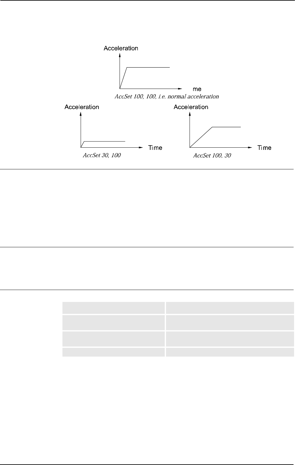
Basic examples
Basic examples of the instruction
AccSet are illustrated below.
Example 1
AccSet 50, 100;
The acceleration is limited to 50% of the normal value.
Example 2
AccSet 100, 50;
The acceleration ramp is limited to 50% of the normal value.
Arguments
AccSet Acc Ramp
Acc
Data type: num
Acceleration and deceleration as a percentage of the normal values. 100% corresponds to
maximum acceleration. Maximum value: 100%. Input value < 20% gives 20% of maximum
acceleration.
Ramp
Data type: num
The rate at which acceleration and deceleration increases as a percentage of the normal
values. Jerking can be restricted by reducing this value. 100% corresponds to maximum rate.
Maximum value: 100%. Input value < 10% gives 10% of maximum rate.
Continues on next page
1 Instructions
1.1. AccSet - Reduces the acceleration
RobotWare - OS
3HAC 16581-1 Revision: J16
© Copyright 2004-2010 ABB. All rights reserved.
The figures show that reducing the acceleration results in smoother movements.
xx0500002146
Program execution
The acceleration applies to both the robot and external axes until a new
AccSet instruction
is executed.
The default values (100%) are automatically set
• at a cold start.
• when a new program is loaded.
• when starting program execution from the beginning.
Syntax
AccSet
[ Acc ':=' ] < expression (IN) of num > ','
[ Ramp ':=' ] < expression (IN) of num > ';'
Related information
Ti
For information about See
Control acceleration in world coordinate
system
WorldAccLim - Control acceleration in world
coordinate system on page 707
Reduce TCP acceleration along the
path
PathAccLim - Reduce TCP acceleration along the
path on page 295
Positioning instructions Technical reference manual - RAPID overview
Continued

1 Instructions
1.2. ActUnit - Activates a mechanical unit
RobotWare - OS
173HAC 16581-1 Revision: J
© Copyright 2004-2010 ABB. All rights reserved.
1.2. ActUnit - Activates a mechanical unit
Usage
ActUnit is used to activate a mechanical unit.
It can be used to determine which unit is to be active when, for example, common drive units
are used.
This instruction can only be used in the main task
T_ROB1 or, if in a MultiMove system, in
Motion tasks.
Basic examples
A basic example of the instruction
ActUnit is illustrated below.
Example 1
ActUnit orbit_a;
Activation of the orbit_a mechanical unit.
Arguments
ActUnit MechUnit
MechUnit
Mechanical Unit
Data type:
mecunit
The name of the mechanical unit that is to be activated.
Program execution
When the robots and external axes actual path is ready, the path on current path level is
cleared and the specified mechanical unit is activated. This means that it is controlled and
monitored by the robot.
If several mechanical units share a common drive unit, activation of one of these mechanical
units will also connect that unit to the common drive unit.
Limitations
If this instruction is preceded by a move instruction, that move instruction must be
programmed with a stop point (zonedata
fine), not a fly-by point, otherwise restart after
power failure will not be possible.
ActUnit cannot be executed in a RAPID routine connected to any of the following special
system events: PowerOn, Stop, QStop, Restart, Reset.or Step.
It is possible to use
ActUnit - DeactUnit on StorePath level, but the same mechanical
units must be active when doing
RestoPath as when StorePath was done. Such operation
on the Path Recorder and the path on the base level will be intact, but the path on the
StorePath level will be cleared.
Syntax
ActUnit
[MechUnit ':=' ] < variable (VAR) of mecunit> ';'
Continues on next page

1 Instructions
1.2. ActUnit - Activates a mechanical unit
RobotWare - OS
3HAC 16581-1 Revision: J18
© Copyright 2004-2010 ABB. All rights reserved.
Related information
For information about See
Deactivating mechanical units DeactUnit - Deactivates a mechanical unit on page 79
Mechanical units mecunit - Mechanical unit on page 1139
More examples DeactUnit - Deactivates a mechanical unit on page 79
Path Recorder PathRecMoveBwd - Move path recorder backwards on
page 298
Continued

1 Instructions
1.3. Add - Adds a numeric value
RobotWare - OS
193HAC 16581-1 Revision: J
© Copyright 2004-2010 ABB. All rights reserved.
1.3. Add - Adds a numeric value
Usage
Add is used to add or subtract a value to or from a numeric variable or persistent.
Basic examples
Basic examples of the instruction
Add are illustrated below.
Example 1
Add reg1, 3;
3
is added to reg1, i.e. reg1:=reg1+3.
Example 2
Add reg1, -reg2;
The value of reg2 is subtracted from reg1, i.e. reg1:=reg1-reg2.
Example 3
VAR dnum mydnum:=5;
Add mydnum, 500000000;
500000000
is added to mydnum, i.e. mynum:=mynum+500000000.
Example 4
VAR dnum mydnum:=5000;
VAR num mynum:=6000;
Add mynum, DnumToNum(mydnum \Integer);
5000
is added to mynum, i.e. mynum:=mynum+5000. You have to use DnumToNum to get a
num numeric value that you can use together with the num variable mynum.
Arguments
Add Name | Dname AddValue | AddDvalue
Name
Data type: num
The name of the variable or persistent to be changed.
Dname
Data type: dnum
The name of the variable or persistent to be changed.
AddValue
Data type: num
The value to be added.
AddDvalue
Data type: dnum
The value to be added.
Continues on next page

1 Instructions
1.3. Add - Adds a numeric value
RobotWare - OS
3HAC 16581-1 Revision: J20
© Copyright 2004-2010 ABB. All rights reserved.
Limitations
If the value to be added is of the type
dnum, and the variable/persistent that should be changed
is a
num, a runtime error will be generated. The combination of arguments is not possible (see
Example 4 above how to solve this).
Syntax
Add
[ Name ':=' ] < var or pers (INOUT) of num >
| [ Dname’ :=’ ] < var or pers (INOUT) of dnum > ’,’
[ AddValue ':=' ] < expression (IN) of num >
| [ AddDvalue’ :=’ ] < expression (IN) of dnum > ’;’
Related information
For information about See
Incrementing a variable by 1 Incr - Increments by 1 on page 131
Decrementing a variable by 1 Decr - Decrements by 1 on page 81
Changing data using an arbitrary
expression, e.g. multiplication
":=" - Assigns a value on page 24
Continued

1 Instructions
1.4. AliasIO - Define I/O signal with alias name
RobotWare - OS
213HAC 16581-1 Revision: J
© Copyright 2004-2010 ABB. All rights reserved.
1.4. AliasIO - Define I/O signal with alias name
Usage
AliasIO is used to define a signal of any type with an alias name or to use signals in built-
in task modules.
Signals with alias names can be used for predefined generic programs, without any
modification of the program before running in different robot installations.
The instruction
AliasIO must be run before any use of the actual signal. See Basic examples
on page 21 for loaded modules, and More examples on page 22 for installed modules.
Basic examples
A basic example of the instruction
AliasIO is illustrated below.
See also More examples on page 22.
Example 1
VAR signaldo alias_do;
PROC prog_start()
AliasIO config_do, alias_do;
ENDPROC
The routine prog_start is connected to the START event in system parameters. The
program defining digital output signal
alias_do is connected to the configured digital
output signal
config_do at program start.
Arguments
AliasIO FromSignal ToSignal
FromSignal
Data type: signalxx or string
Loaded modules:
The signal identifier named according to the configuration (data type
signalxx) from which
the signal descriptor is copied. The signal must be defined in the I/O configuration.
Installed modules or loaded modules:
A reference (
CONST, VAR or parameter of these) containing the name of the signal (data type
string) from which the signal descriptor after search in the system is copied. The signal
must be defined in the I/O configuration.
ToSignal
Data type: signalxx
The signal identifier according to the program (data type signalxx) to which the signal
descriptor is copied. The signal must be declared in the RAPID program.
The same data type must be used (or found) for the arguments
FromSignal and ToSignal
and must be one of type signalxx (signalai, signalao, signaldi, signaldo,
signalgi, or signalgo).
Continues on next page

1 Instructions
1.4. AliasIO - Define I/O signal with alias name
RobotWare - OS
3HAC 16581-1 Revision: J22
© Copyright 2004-2010 ABB. All rights reserved.
Program execution
The signal descriptor value is copied from the signal given in argument
FromSignal to the
signal given in argument
ToSignal.
Error handling
Following recoverable errors can be generated. The errors can be handled in an error handler.
The system variable
ERRNO will be set to:
More examples
More examples of the instruction
AliasIO are illustrated below.
Example 1
VAR signaldi alias_di;
PROC prog_start()
CONST string config_string := "config_di";
AliasIO config_string, alias_di;
ENDPROC
The routine prog_start is connected to the START event in system parameters. The
program defined digital input signal
alias_di is connected to the configured digital input
signal
config_di (via constant config_string) at program start.
Limitation
When starting the program, the alias signal cannot be used until the
AliasIO instruction is
executed.
Instruction
AliasIO must be placed
• either in the event routine executed at program start (event START)
• or in the program part executed after every program start (before use of the signal)
In order to prevent mistakes it is not recommended to use dynamic reconnection of an
AliasIO signal to different physical signals.
Syntax
AliasIO
[ FromSignal ':=' ] < reference (REF) of anytype> ','
[ ToSignal ':=' ] < variable (VAR) of anytype> ';'
ERR_ALIASIO_DEF The FromSignal is not defined in the IO configuration
or the ToSignal is not declared in the RAPID program
or the ToSignal is defined in the IO configuration.
ERR_ALIASIO_TYPE The data types for the arguments FromSignal and
ToSignal is not the same type.
Continued
Continues on next page

1 Instructions
1.4. AliasIO - Define I/O signal with alias name
RobotWare - OS
233HAC 16581-1 Revision: J
© Copyright 2004-2010 ABB. All rights reserved.
Related information
For information about See
Input/Output instructions Technical reference manual - RAPID overview
Input/Output functionality in general Technical reference manual - RAPID overview
Configuration of I/O Technical reference manual - System parameters
Defining event routines Technical reference manual - System parameters
Loaded/Installed task modules Technical reference manual - System parameters
Continued

1 Instructions
1.5. ":=" - Assigns a value
RobotWare - OS
3HAC 16581-1 Revision: J24
© Copyright 2004-2010 ABB. All rights reserved.
1.5. ":=" - Assigns a value
Usage
The “
:=” instruction is used to assign a new value to data. This value can be anything from a
constant value to an arithmetic expression, e.g.
reg1+5*reg3.
Basic examples
Basic examples of the instruction “
:=” are illustrated below.
See also More examples on page 24.
Example 1
reg1 := 5;
reg1
is assigned the value 5.
Example 2
reg1 := reg2 - reg3;
reg1
is assigned the value that the reg2-reg3 calculation returns.
Example 3
counter := counter + 1;
counter
is incremented by one.
Arguments
Data := Value
Data
Data type: All
The data that is to be assigned a new value.
Value
Data type: Same as Data
The desired value.
More examples
More examples of the instruction “
:=” are illustrated below.
Example 1
tool1.tframe.trans.x := tool1.tframe.trans.x + 20;
The TCP for tool1 is shifted 20 mm in the X-direction.
Example 2
pallet{5,8} := Abs(value);
An element in the pallet matrix is assigned a value equal to the absolute value of the value
variable.
Continues on next page

1 Instructions
1.5. ":=" - Assigns a value
RobotWare - OS
253HAC 16581-1 Revision: J
© Copyright 2004-2010 ABB. All rights reserved.
Limitations
The data (whose value is to be changed) must not be
• a constant
• a non-value data type.
The data and value must have similar (the same or alias) data types.
Syntax
(EBNF)
<assignment target> ':=' <expression> ';'
<assignment target> ::=
<variable>
| <persistent>
| <parameter>
| <VAR>
Related information
For information about See
Expressions Technical reference manual - RAPID overview
Non-value data types Technical reference manual - RAPID overview
Assigning an initial value to data Operating manual - IRC5 with FlexPendant
Continued
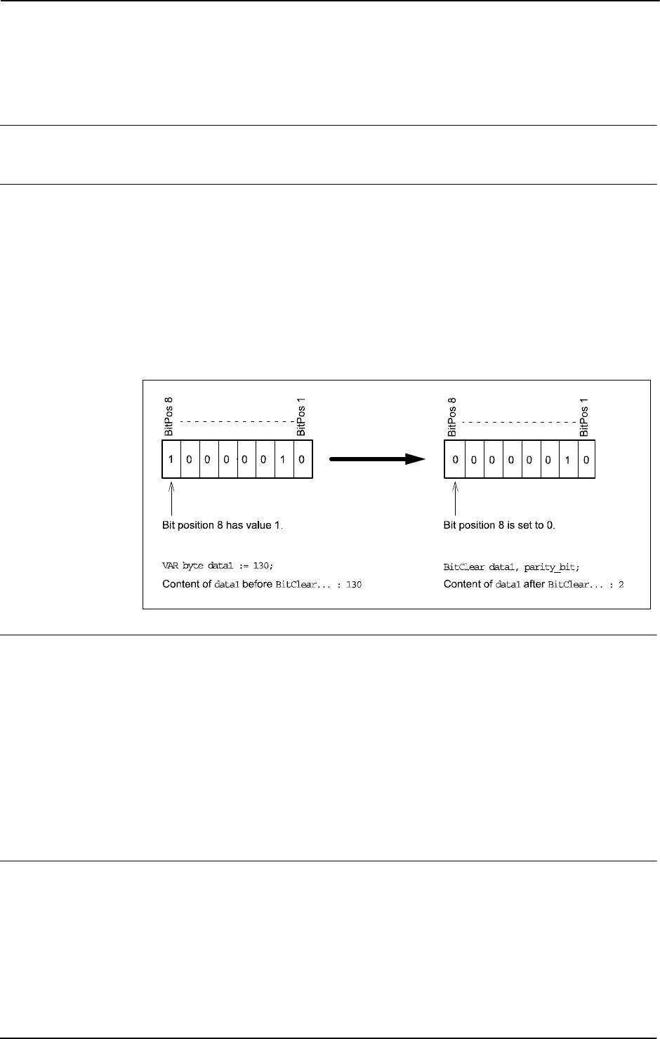
1 Instructions
1.6. BitClear - Clear a specified bit in a byte data
RobotWare - OS
3HAC 16581-1 Revision: J26
© Copyright 2004-2010 ABB. All rights reserved.
1.6. BitClear - Clear a specified bit in a byte data
Usage
BitClear is used to clear (set to 0) a specified bit in a defined byte data.
Basic examples
A basic example of the instruction
BitClear is illustrated below.
Example 1
CONST num parity_bit := 8;
VAR byte data1 := 130;
BitClear data1, parity_bit;
Bit number 8 (parity_bit) in the variable data1 will be set to 0, e.g. the content of the variable
data1 will be changed from 130 to 2 (integer representation). Bit manipulation of data type
byte when using BitClear is illustrated in the figure below.
xx0500002147
Arguments
BitClear BitData BitPos
BitData
Data type: byte
The bit data, in integer representation, to be changed.
BitPos
Bit Position
Data type:
num
The bit position (1-8) in the BitData to be set to 0.
Limitations
The range for a data type
byte is 0 - 255 decimal.
The bit position is valid from 1 - 8.
Continues on next page

1 Instructions
1.6. BitClear - Clear a specified bit in a byte data
RobotWare - OS
273HAC 16581-1 Revision: J
© Copyright 2004-2010 ABB. All rights reserved.
Syntax
BitClear
[ BitData ':=' ] < var or pers (INOUT) of byte > ','
[ BitPos ':=' ] < expression (IN) of num > ';'
Related information
For information about See
Set a specified bit in a byte data BitSet - Set a specified bit in a byte data on page
28
Check if a specified bit in a byte data is set BitCheck - Check if a specified bit in a byte data
is set on page 772
Other bit functions Technical reference manual - RAPID overview
Continued

1 Instructions
1.7. BitSet - Set a specified bit in a byte data
RobotWare - OS
3HAC 16581-1 Revision: J28
© Copyright 2004-2010 ABB. All rights reserved.
1.7. BitSet - Set a specified bit in a byte data
Usage
BitSet is used to set a specified bit to 1 in a defined byte data.
Basic examples
A basic example of the instruction
BitSet is illustrated below.
Example 1
CONST num parity_bit := 8;
VAR byte data1 := 2;
BitSet data1, parity_bit;
Bit number 8 (parity_bit) in the variable data1 will be set to 1, e.g. the content of the
variable
data1 will be changed from 2 to 130 (integer representation). Bit manipulation of
data type
byte when using BitSet is illustrated in the figure below.
xx0500002148
Arguments
BitSet BitData BitPos
BitData
Data type: byte
The bit data, in integer representation, to be changed.
BitPos
Bit Position
Data type:
num
The bit position (1-8) in the BitData to be set to 1.
Limitations
The range for a data type
byte is integer 0 - 255.
The bit position is valid from 1 - 8.
Continues on next page

1 Instructions
1.7. BitSet - Set a specified bit in a byte data
RobotWare - OS
293HAC 16581-1 Revision: J
© Copyright 2004-2010 ABB. All rights reserved.
Syntax
BitSet
[ BitData':=' ] < var or pers (INOUT) of byte > ','
[ BitPos':=' ] < expression (IN) of num > ';'
Related information
For information about See
Clear a specified bit in a byte data BitClear - Clear a specified bit in a byte data
on page 26
Check if a specified bit in a byte data is set BitCheck - Check if a specified bit in a byte
data is set on page 772
Other bit functions Technical reference manual - RAPID
overview
Continued

1 Instructions
1.8. BookErrNo - Book a RAPID system error number
RobotWare - OS
3HAC 16581-1 Revision: J30
© Copyright 2004-2010 ABB. All rights reserved.
1.8. BookErrNo - Book a RAPID system error number
Usage
BookErrNo is used to book a new RAPID system error number.
Basic examples
A basic example of the instruction
BookErrNo is illustrated below.
Example 1
! Introduce a new error number in a glue system
! Note: The new error variable must be declared with the initial
value -1
VAR errnum ERR_GLUEFLOW := -1;
! Book the new RAPID system error number
BookErrNo ERR_GLUEFLOW;
The variable ERR_GLUEFLOW will be assigned to a free system error number for use in the
RAPID code.
! Use the new error number
IF di1 = 0 THEN
RAISE ERR_GLUEFLOW;
ELSE
...
ENDIF
! Error handling
ERROR
IF ERRNO = ERR_GLUEFLOW THEN
...
ELSE
...
ENDIF
If the digital input di1 is 0, the new booked error number will be raised and the system error
variable
ERRNO will be set to the new booked error number. The error handling of those user
generated errors can then be handled in the error handler as usual.
Arguments
BookErrNo ErrorName
ErrorName
Data type: errnum
The new RAPID system error variable name.
Limitations
The new error variable must not be declared as a routine variable.
The new error variable must be declared with an initial value of -1, that gives the information
that this error should be a RAPID system error.
Continues on next page

1 Instructions
1.8. BookErrNo - Book a RAPID system error number
RobotWare - OS
313HAC 16581-1 Revision: J
© Copyright 2004-2010 ABB. All rights reserved.
Syntax
BookErrNo
[ ErrorName ':='] < variable (VAR) of errnum > ';'
Related information
For information about See
Error handling Technical reference manual - RAPID overview
Error number errnum - Error number on page 1108
Call an error handler RAISE - Calls an error handler on page 334
Continued

1 Instructions
1.9. Break - Break program execution
RobotWare - OS
3HAC 16581-1 Revision: J32
© Copyright 2004-2010 ABB. All rights reserved.
1.9. Break - Break program execution
Usage
Break is used to make an immediate break in program execution for RAPID program code
debugging purposes. The robot movement is stopped at once.
Basic examples
A basic example of the instruction
Break is illustrated below.
Example 1
...
Break;
...
Program execution stops and it is possible to analyze variables, values etc. for debugging
purposes.
Program execution
The instruction stops program execution at once, without waiting for the robot and external
axes to reach their programmed destination points for the movement being performed at the
time. Program execution can then be restarted from the next instruction.
If there is a
Break instruction in some routine event, the execution of the routine will be
interrupted and no STOP routine event will be executed. The routine event will be executed
from the beginning the next time the same event occurs.
Syntax
Break';'
Related information
For information about See
Stopping for program actions Stop - Stops program execution on page 510
Stopping after a fatal error EXIT - Terminates program execution on page 105
Terminating program execution EXIT - Terminates program execution on page 105
Only stopping robot movements StopMove - Stops robot movement on page 515

1 Instructions
1.10. CallByVar - Call a procedure by a variable
RobotWare - OS
333HAC 16581-1 Revision: J
© Copyright 2004-2010 ABB. All rights reserved.
1.10. CallByVar - Call a procedure by a variable
Usage
CallByVar (Call By Variable) can be used to call procedures with specific names, e.g.
proc_name1, proc_name2, proc_name3 ... proc_namex via a variable.
Basic examples
A basic example of the instruction
CallByVar is illustrated below.
See also More examples on page 33.
Example 1
reg1 := 2;
CallByVar "proc", reg1;
The procedure proc2 is called.
Arguments
CallByVar Name Number
Name
Data type: string
The first part of the procedure name, e.g. proc_name.
Number
Data type: num
The numeric value for the number of the procedure. This value will be converted to a string
and gives the 2nd part of the procedure name, e.g.
1. The value must be a positive integer.
More examples
More examples of how to make static and dynamic selection of procedure call.
Example 1 - Static selection of procedure call
TEST reg1
CASE 1:
lf_door door_loc;
CASE 2:
rf_door door_loc;
CASE 3:
lr_door door_loc;
CASE 4:
rr_door door_loc;
DEFAULT:
EXIT;
ENDTEST
Depending on whether the value of register reg1 is 1, 2, 3, or 4, different procedures are
called that perform the appropriate type of work for the selected door. The door location in
argument
door_loc.
Continues on next page

1 Instructions
1.10. CallByVar - Call a procedure by a variable
RobotWare - OS
3HAC 16581-1 Revision: J34
© Copyright 2004-2010 ABB. All rights reserved.
Example 2 - Dynamic selection of procedure call with RAPID syntax
reg1 := 2;
%"proc"+NumToStr(reg1,0)% door_loc;
The procedure proc2 is called with argument door_loc.
Limitation: All procedures must have a specific name e.g.
proc1, proc2, proc3.
Example 3 - Dynamic selection of procedure call with CallByVar
reg1 := 2;
CallByVar "proc",reg1;
The procedure proc2 is called.
Limitation: All procedures must have specific name, e.g.
proc1, proc2, proc3, and no
arguments can be used.
Limitations
Can only be used to call procedures without parameters.
Can not be used to call LOCAL procedures.
Execution of
CallByVar takes a little more time than execution of a normal procedure call.
Error handling
In the argument
Number is < 0 or is not an integer, the system variable ERRNO is set to
ERR_ARGVALERR.
In reference to an unknown procedure, the system variable ERRNO is set to
ERR_REFUNKPRC.
In procedure call error (not procedure), the system variable ERRNO is set to
ERR_CALLPROC.
These errors can be handled in the error handler.
Syntax
CallByVar
[Name ':='] <expression (IN) of string>','
[Number ':='] <expression (IN) of num>';'
Related information
For information about See
Calling procedures Technical reference manual - RAPID overview
Operating manual - IRC5 with FlexPendant
Continued

1 Instructions
1.11. CancelLoad - Cancel loading of a module
RobotWare - OS
353HAC 16581-1 Revision: J
© Copyright 2004-2010 ABB. All rights reserved.
1.11. CancelLoad - Cancel loading of a module
Usage
CancelLoad can be used to cancel the loading operation generated from the instruction
StartLoad.
CancelLoad can only be used between the instruction StartLoad and WaitLoad.
Basic examples
A basic example of the instruction
CancelLoad is illustrated below.
See also More examples on page 35.
Example1
CancelLoad load1;
The load session load1 is cancelled.
Arguments
CancelLoad LoadNo
LoadNo
Data type: loadsession
Reference to the load session, created by the instruction StartLoad.
More examples
More examples of how to use the instruction
CancelLoad are illustrated below.
Example 1
VAR loadsession load1;
StartLoad "HOME:"\File:="PART_B.MOD",load1;
...
IF ...
CancelLoad load1;
StartLoad "HOME:"\File:="PART_C.MOD",load1;
ENDIF
...
WaitLoad load1;
The instruction CancelLoad will cancel the on-going loading of the module PART_B.MOD
and instead make it possible to load
PART_C.MOD.
Error handling
If the variable specified in argument
LoadNo is not in use, meaning that no load session is in
use, the system variable ERRNO is set to ERR_LOADNO_NOUSE. This error can then be
handled in the error handler.
Limitation
CancelLoad can only be used in the sequence after that instruction StartLoad is ready and
before instruction
WaitLoad is started.
Continues on next page

1 Instructions
1.11. CancelLoad - Cancel loading of a module
RobotWare - OS
3HAC 16581-1 Revision: J36
© Copyright 2004-2010 ABB. All rights reserved.
Syntax
CancelLoad
[ LoadNo ':=' ] < variable (VAR) of loadsession >';'
Related information
For information about See
Load a program module during
execution
StartLoad - Load a program module during
execution on page 482
Connect the loaded module to the task WaitLoad - Connect the loaded module to the task
on page 682
Load session loadsession - Program load session on page 1138
Load a program module Load - Load a program module during execution on
page 208
Unload a program module UnLoad - UnLoad a program module during
execution on page 655
Check program references CheckProgRef - Check program references on
page 37
Continued

1 Instructions
1.12. CheckProgRef - Check program references
RobotWare - OS
373HAC 16581-1 Revision: J
© Copyright 2004-2010 ABB. All rights reserved.
1.12. CheckProgRef - Check program references
Usage
CheckProgRef is used to check for unresolved references at any time during execution.
Basic examples
A basic example of the instruction
CheckProgRef is illustrated below.
Example 1
Load \Dynamic, diskhome \File:="PART_B.MOD" \CheckRef;
Unload "PART_A.MOD";
CheckProgRef;
In this case the program contains a module called PART_A.MOD. A new module PART_B.MOD
is loaded, which checks if all references are OK. Then
PART_A.MOD is unloaded. To check
for unresolved references after unload, a call to
CheckProgRef is done.
Program execution
Program execution forces a new link of the program task and checks for unresolved
references.
If an error occurs during
CheckProgRef, the program is not affected, it just tells you that an
unresolved reference exists in the program task. Therefore, use
CheckProgRef immediately
after changing the number of modules in the program task (loading or unloading) to be able
to know which module caused the link error.
This instruction can also be used as a substitute for using the optional argument
\CheckRef
in instruction
Load or WaitLoad.
Error handling
If the program task contains unresolved references, the system variable ERRNO will be set
to ERR_LINKREF, which can be handled in the error handler.
Syntax
CheckProgRef';'
Related information
For information about See
Load of a program module Load - Load a program module during
execution on page 208
Unload of a program module UnLoad - UnLoad a program module during
execution on page 655
Start loading of a program module StartLoad - Load a program module during
execution on page 482
Finish loading of a program module WaitLoad - Connect the loaded module to the
task on page 682

1 Instructions
1.13. CirPathMode - Tool reorientation during circle path
RobotWare - OS
3HAC 16581-1 Revision: J38
© Copyright 2004-2010 ABB. All rights reserved.
1.13. CirPathMode - Tool reorientation during circle path
Usage
CirPathMode (Circle Path Mode) makes it possible to select different modes to reorientate
the tool during circular movements.
This instruction can only be used in the main task
T_ROB1 or, if in a MultiMove system in
Motion tasks.
Basic examples
Basic examples of the instruction
CirPathMode are illustrated below.
Example 1
CirPathMode \PathFrame;
Standard mode for tool reorientation in the actual path frame from the start point to the
ToPoint during all succeeding circular movements. This is default in the system.
Example 2
CirPathMode \ObjectFrame;
Modified mode for tool reorientation in actual object frame from the start point to the
ToPoint during all succeeding circular movements.
Example 3
CirPathMode \CirPointOri;
Modified mode for tool reorientation from the start point via the programmed CirPoint
orientation to the
ToPoint during all succeeding circular movements.
Example 4
CirPathMode \Wrist45;
Modified mode such that the projection of the tool’s z-axis onto the cut plane will follow the
programmed circle segment. Only wrist axes 4 and 5 are used. This mode should only be used
for thin objects.
Example 5
CirPathMode \Wrist46;
Modified mode such that the projection of the tool’s z-axis onto the cut plane will follow the
programmed circle segment. Only wrist axes 4 and 6 are used. This mode should only be used
for thin objects.
Example 6
CirPathMode \Wrist56;
Modified mode such that the projection of the tool’s z-axis onto the cut plane will follow the
programmed circle segment. Only wrist axes 5 and 6 are used. This mode should only be used
for thin objects.
Continues on next page
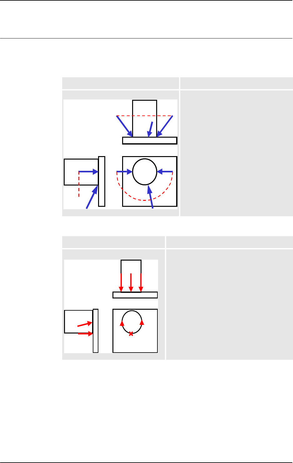
1 Instructions
1.13. CirPathMode - Tool reorientation during circle path
RobotWare - OS
393HAC 16581-1 Revision: J
© Copyright 2004-2010 ABB. All rights reserved.
Description
PathFrame
The figure in the table shows the tool reorientation for the standard mode \PathFrame.
The figure in the table shows the use of standard mode
\PathFrame with fixed tool orienta-
tion.
Illustration Description
xx0500002152
The arrows shows the tool from wrist center
point to tool center point for the programmed
points. The path for the wrist center point is
dotted in the figure.
The \PathFrame mode makes it easy to get
the same angle of the tool around the
cylinder. The robot wrist will not go through
the programmed orientation in the
CirPoint
Illustration Description
xx0500002153
This picture shows the obtained orientation of the
tool in the middle of the circle using a leaning tool
and \PathFrame mode.
Compare with the figure below when
\ObjectFrame mode is used.
Continued
Continues on next page
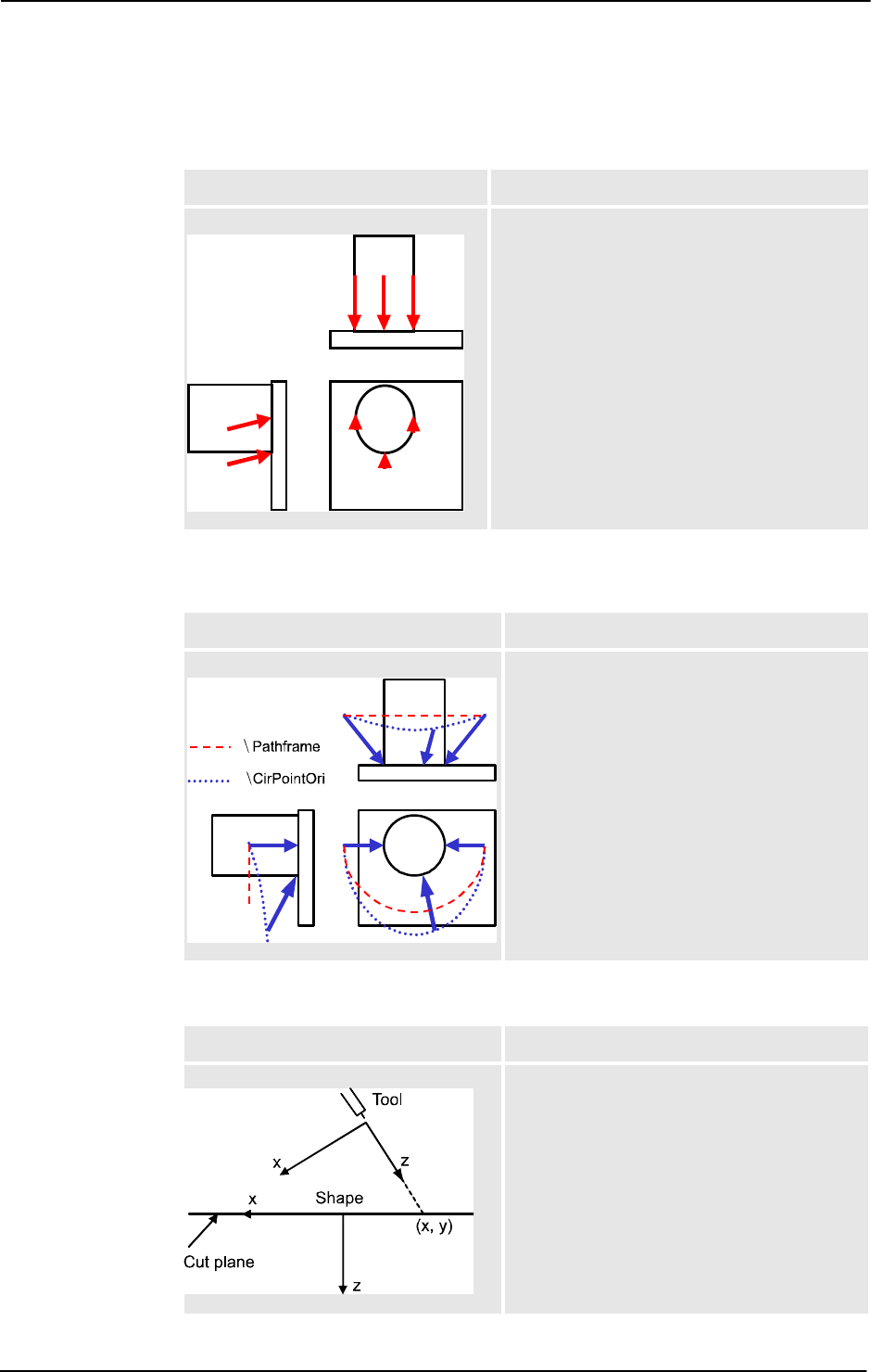
1 Instructions
1.13. CirPathMode - Tool reorientation during circle path
RobotWare - OS
3HAC 16581-1 Revision: J40
© Copyright 2004-2010 ABB. All rights reserved.
ObjectFrame
The figure in the table shows the use of modified mode \ObjectFrame with fixed tool ori-
entation.
CirPointOri
The figure in the table shows the different tool reorientation between the standard mode
\PathFrame and the modified mode \CirPointOri.
Wrist45 / Wrist46 / Wrist56
The figure in the table shows the frames involved when cutting a shape using axes 4 and 5..
Illustration Description
xx0500002151
This picture shows the obtained orientation of the
tool in the middle of the circle using a leaning tool
and \ObjectFrame mode.
This mode will make a linear reorientation of the
tool in the same way as for MoveL. The robot wrist
will not go through the programmed orientation in
the CirPoint.
Compare with the figure above when
\PathFrame mode is used.
Illustration Description
xx0500002150
The arrows show the tool from wrist center point
to tool center point for the programmed points.
The different paths for the wrist center point are
dashed in the figure.
The \CirPointOri mode will make the robot
wrist to go through the programmed orientation
in the CirPoint.
Illustration Description
xx0800000294
It is assumed that the cutting beam is aligned
with the tool’s z axis. The coordinate frame of the
cut plane is defined by the robot’s starting
position when executing the MoveC instruction.
Continued
Continues on next page

1 Instructions
1.13. CirPathMode - Tool reorientation during circle path
RobotWare - OS
413HAC 16581-1 Revision: J
© Copyright 2004-2010 ABB. All rights reserved.
Arguments
CirPathMode [\PathFrame] | [\ObjectFrame] | [\CirPointOri] |
[\Wrist45] | [\Wrist46] | [\Wrist56]
[ \PathFrame ]
Data type: switch
During the circular movement the reorientation of the tool is done continuously from the start
point orientation to the
ToPoint orientation in the actual path frame. This is the standard
mode in the system.
[ \ObjectFrame ]
Data type: switch
During the circular movement the reorientation of the tool is done continuously from the start
point orientation to the
ToPoint orientation in the actual object frame.
[ \CirPointOri ]
Data type: switch
During the circular movement the reorientation of the tool is done continuously from the start
point orientation to the programmed
CirPoint orientation and further to the ToPoint
orientation.
[ \Wrist45 ]
Data type: switch
The robot will move axes 4 and 5 such that the projection of the tool’s z-axis onto the cut
plane will follow the programmed circle segment. This mode should only be used for thin
objects as only 2 wrist axes are used and thus give us increased accuracy but also less control.
NOTE: This switch requires option Wrist Move.
[ \Wrist46 ]
Data type: switch
The robot will move axes 4 and 6 such that the projection of the tool’s z-axis onto the cut
plane will follow the programmed circle segment. This mode should only be used for thin
objects as only 2 wrist axes are used and thus give us increased accuracy but also less control.
NOTE: This switch requires option Wrist Move.
[ \Wrist56 ]
Data type: switch
The robot will move axes 5 and 6 such that the projection of the tool’s z-axis onto the cut
plane will follow the programmed circle segment. This mode should only be used for thin
objects as only 2 wrist axes are used and thus give us increased accuracy but also less control.
NOTE: This switch requires option Wrist Move.
If you use
CirPathMode without any switch then result is the same as CirPointMode
\PathFrame
Continued
Continues on next page
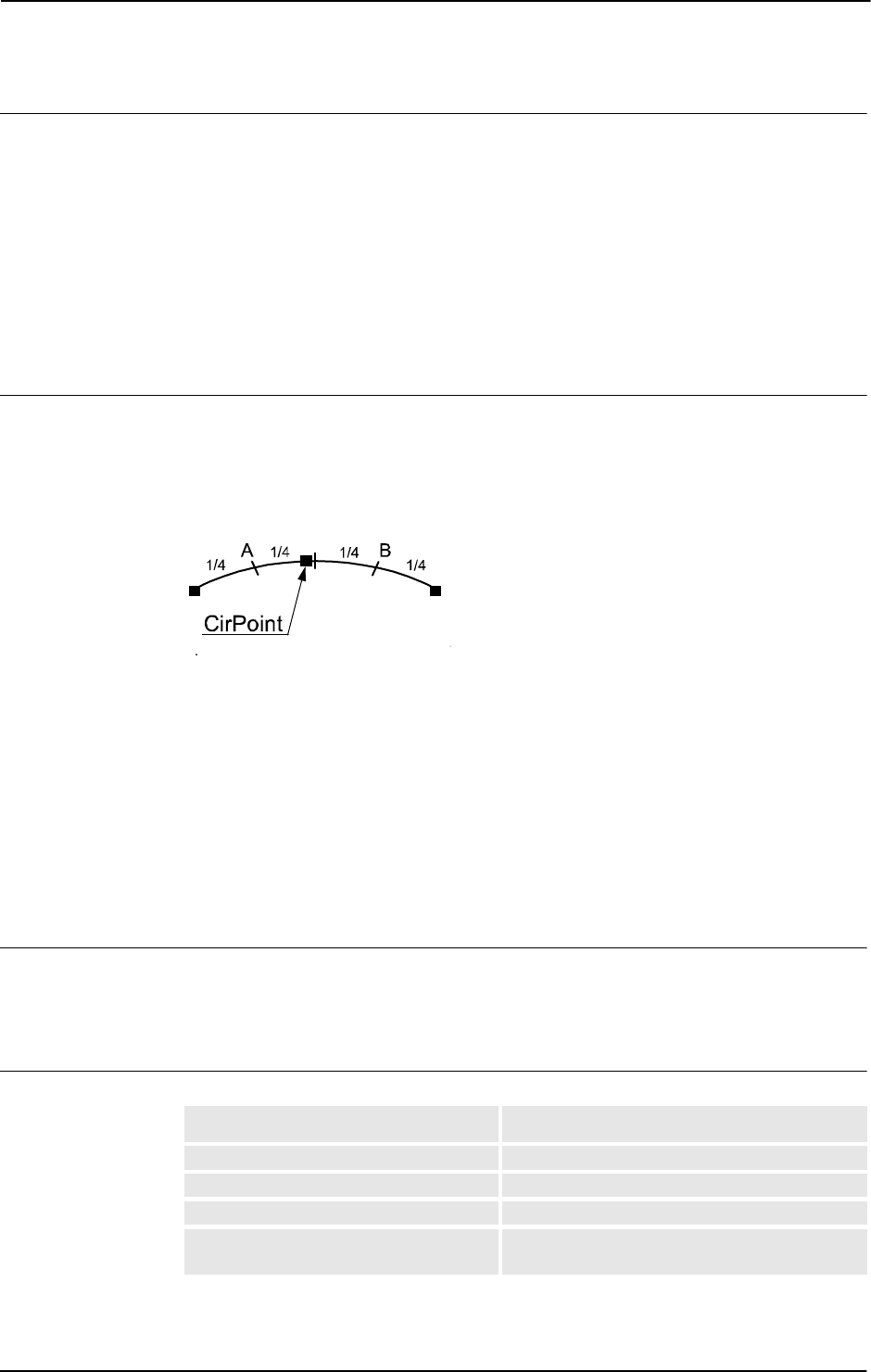
1 Instructions
1.13. CirPathMode - Tool reorientation during circle path
RobotWare - OS
3HAC 16581-1 Revision: J42
© Copyright 2004-2010 ABB. All rights reserved.
Program execution
The specified circular tool reorientation mode applies for the next executed robot circular
movements of any type (
MoveC, SearchC, TriggC, MoveCDO, MoveCSync, ArcC,
PaintC
... ) and is valid until a new CirPathMode (or obsolete CirPathReori) instruction
is executed.
The standard circular reorientation mode (
CirPathMode \PathFrame) is automatically set
• At a cold start-up.
• When a new program is loaded.
• When starting program execution from the beginning.
Limitations
The instruction only affects circular movements.
When using the
\CirPointOri mode, the CirPoint must be between the points A and B
according to the figure below to make the circle movement to go through the programmed
orientation in the
CirPoint.
xx0500002149
\Wrist45, \Wrist46, and \Wrist56 mode should only be used for cutting thin objects as
the ability to control the angle of the tool is lost when using only two wrist axes. Coordinated
movements are not possible since the main axis is locked.
If working in wrist singularity area and the instruction
SingArea\Wrist has been executed,
the instruction
CirPathMode has no effect because the system then selects another tool
reorientation mode for circular movements (joint interpolation).
This instruction replaces the old instruction
CirPathReori (will work even in the future but
will not be documented any more).
Syntax
CirPathMode
['\'PathFrame] | ['\'ObjectFrame] | ['\'CirPointOri] |
['\'Wrist45] | ['\'Wrist46] | ['\'Wrist56] ';'
Related information
For information about See
Interpolation Technical reference manual - RAPID overview
Motion settings data motsetdata - Motion settings data on page 1141
Circular move instruction MoveC - Moves the robot circularly on page 236
Wrist movements Application manual - Motion Performance,
section Wrist Move
Continued

1 Instructions
1.14. Clear - Clears the value
RobotWare - OS
433HAC 16581-1 Revision: J
© Copyright 2004-2010 ABB. All rights reserved.
1.14. Clear - Clears the value
Usage
Clear is used to clear a numeric variable or persistent , i.e. set it to 0.
Basic examples
Basic examples of the instruction
Clear are illustrated below.
Example 1
Clear reg1;
Reg1
is cleared, i.e. reg1:=0.
Example 2
CVAR dnum mydnum:=5;
Clear mydnum;
mydnum
is cleared, i.e. mydnum:=0.
Arguments
Clear Name | Dname
Name
Data type: num
The name of the variable or persistent to be cleared.
Dname
Data type: dnum
The name of the variable or persistent to be cleared.
Syntax
Clear
[ Name ':=' ] < var or pers (INOUT) of num >
| [ Dname ':=' ] < var or pers (INOUT) of dnum > ';'
Related information
For information about See
Incrementing a variable by 1 Incr - Increments by 1 on page 131
Decrementing a variable by 1 Decr - Decrements by 1 on page 81
Adding any value to a variable Add - Adds a numeric value on page 19
Changing data using arbitrary ":=" - Assigns a value on page 24

1 Instructions
1.15. ClearIOBuff - Clear input buffer of a serial channel
RobotWare - OS
3HAC 16581-1 Revision: J44
© Copyright 2004-2010 ABB. All rights reserved.
1.15. ClearIOBuff - Clear input buffer of a serial channel
Usage
ClearIOBuff (Clear I/O Buffer) is used to clear the input buffer of a serial channel. All
buffered characters from the input serial channel are discarded.
Basic examples
A basic example of the instruction
ClearIOBuff is illustrated below.
Example 1
VAR iodev channel2;
...
Open "com2:", channel2 \Bin;
ClearIOBuff channel2;
WaitTime 0.1;
The input buffer for the serial channel referred to by channel2 is cleared. The wait time
guarantees the clear operation enough time to finish.
Arguments
ClearIOBuff IODevice
IODevice
Data type: iodev
The name (reference) of the serial channel whose input buffer is to be cleared.
Program execution
All buffered characters from the input serial channel are discarded. Next read instructions will
wait for new input from the channel.
Limitations
This instruction can only be used for serial channels. Do not wait for acknowledgement of the
operation to finish. Allow a wait time 0.1 after the instruction is recommended to give the
operation enough time in every application.
Error handling
If trying to use the instruction on a file, the system variable
ERRNO is set to ERR_FILEACC.
This error can then be handled in the error handler.
Syntax
ClearIOBuff
[IODevice ':='] <variable (VAR) of iodev>';'
Related information
For information about See
Opening a serial channel Technical reference manual - RAPID overview
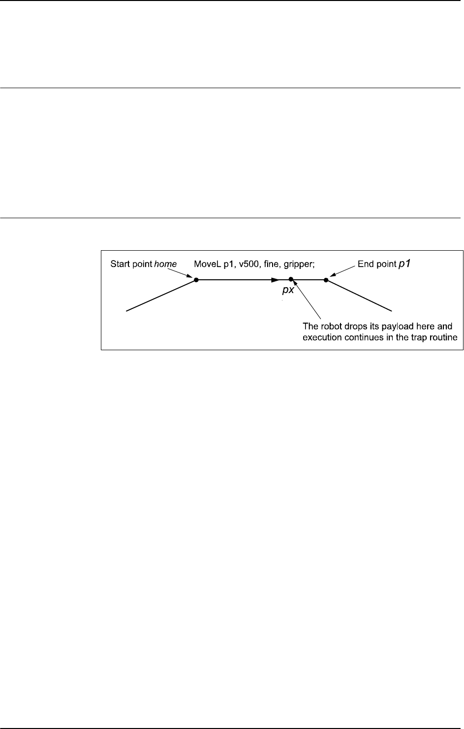
1 Instructions
1.16. ClearPath - Clear current path
Robot Ware - OS
453HAC 16581-1 Revision: J
© Copyright 2004-2010 ABB. All rights reserved.
1.16. ClearPath - Clear current path
Usage
ClearPath (Clear Path) clears the whole motion path on the current motion path level (base
level or
StorePath level).
With motion path, meaning all the movement segments from any move instructions which
have been executed in RAPID but not performed by the robot at the execution time of
ClearPath.
The robot must be in a stop point position or must be stopped with
StopMove before the
instruction
ClearPath can be executed.
Basic examples
Basic examples of the instruction
ClearPath are illustrated below.
xx0500002154
In the following program example, the robot moves from the position home to the position
p1. At the point px the signal di1 will indicate that the payload has been dropped. The
execution continues in the trap routine
gohome. The robot will stop moving (start the braking)
at
px, the path will be cleared, the robot will move to position home. The error will be raised
up to the calling routine
minicycle and the whole user defined program cycle proc1 ..
proc2
will be executed from the beginning one more time.
Example 1
VAR intnum drop_payload;
VAR errnum ERR_DROP_LOAD := -1;
PROC minicycle()
BookErrNo ERR_DROP_LOAD;
proc1;
...
ERROR (ERR_DROP_LOAD)
RETRY;
ENDPROC
PROC proc1()
...
proc2;
...
ENDPROC
Continues on next page

1 Instructions
1.16. ClearPath - Clear current path
Robot Ware - OS
3HAC 16581-1 Revision: J46
© Copyright 2004-2010 ABB. All rights reserved.
PROC proc2()
CONNECT drop_payload WITH gohome;
ISignalDI \Single, di1, 1, drop_payload;
MoveL p1, v500, fine, gripper;
...........
IDelete drop_payload
ENDPROC
TRAP gohome
StopMove \Quick;
ClearPath;
IDelete drop_payload;
StorePath;
MoveL home, v500, fine, gripper;
RestoPath;
RAISE ERR_DROP_LOAD;
ERROR
RAISE;
ENDTRAP
If the same program is being run but without StopMove and ClearPath in the trap routine
gohome, the robot will continue to position p1 before going back to position home.
If programming
MoveL home with flying-point (zone) instead of stop-point (fine), the
movement is going on during the
RAISE to the error handler in procedure minicycle and
further until the movement is ready.
Limitations
Limitation examples of the instruction
ClearPath are illustrated below.
Example 1 - Limitation
VAR intnum int_move_stop;
...
PROC test_move_stop()
CONNECT int_move_stop WITH trap_move_stop;
ISignalDI di1, 1, int_move_stop;
MoveJ p10, v200, z20, gripper;
MoveL p20, v200, z20, gripper;
ENDPROC
TRAP trap_move_stop
StopMove;
ClearPath;
StartMove;
StorePath;
MoveJ p10, v200, z20, gripper;
RestoPath;
ENDTRAP
Continued
Continues on next page

1 Instructions
1.16. ClearPath - Clear current path
Robot Ware - OS
473HAC 16581-1 Revision: J
© Copyright 2004-2010 ABB. All rights reserved.
This is an example of ClearPath limitation. During the robot movement to p10 and p20,
the ongoing movement is stopped and the motion path is cleared, but no action is done to
break off the active instruction
MoveJ p10 or MoveL p20 in the PROC test_move_stop.
So the ongoing movement will be interrupted and the robot will go to
p10 in the TRAP
trap_move_stop
, but no further movement to p10 or p20 in the PROC test_move_stop
will be done. The program execution will be hanging.
This problem can be solved with either error recovery with long jump as described in example
2 below or with asynchronously raised error with instruction
ProcerrRecovery.
Example 2 - No limitations
VAR intnum int_move_stop;
VAR errnum err_move_stop := -1;
...
PROC test_move_stop()
BookErrNo err_move_stop;
CONNECT int_move_stop WITH trap_move_stop;
ISignalDI di1, 1, int_move_stop;
MoveJ p10, v200, z20, gripper;
MoveL p20, v200, z20, gripper;
ERROR (err_move_stop)
StopMove;
ClearPath;
StartMove;
StorePath;
MoveJ p10, v200, z20, gripper;
RestoPath;
RETRY;
ENDPROC
TRAP trap_move_stop
RAISE err_move_stop;
ERROR
RAISE;
ENDTRAP
This is an example of how to use error recovery with long jump together with ClearPath
without any limitation. During the robot movement to p10 and p20, the ongoing movement
is stopped. The motion path is cleared, and because of error recovery through execution level
boundaries, break off is done of the active instruction
MoveJ p10 or MoveL p20. So the
ongoing movement will be interrupted and the robot will go to
p10 in the ERROR handler,
and once more execute the interrupted instruction
MoveJ p10 or MoveL p20 in the PROC
test_move_stop
.
Syntax
ClearPath ';'
Continued
Continues on next page

1 Instructions
1.16. ClearPath - Clear current path
Robot Ware - OS
3HAC 16581-1 Revision: J48
© Copyright 2004-2010 ABB. All rights reserved.
Related information
For information about See
Stop robot movements StopMove - Stops robot movement on page 515
Error recovery Technical reference manual - RAPID overview
Technical reference manual - RAPID kernel
Asynchronously raised error ProcerrRecovery - Generate and recover from process-move
error on page 325
Continued

1 Instructions
1.17. ClearRawBytes - Clear the contents of rawbytes data
RobotWare - OS
493HAC 16581-1 Revision: J
© Copyright 2004-2010 ABB. All rights reserved.
1.17. ClearRawBytes - Clear the contents of rawbytes data
Usage
ClearRawBytes is used to set all the contents of a rawbytes variable to 0.
Basic examples
A basic example of the instruction is illustrated below.
Example 1
VAR rawbytes raw_data;
VAR num integer := 8
VAR num float := 13.4;
PackRawBytes integer, raw_data, 1 \IntX := DINT;
PackRawBytes float, raw_data, (RawBytesLen(raw_data)+1) \Float4;
ClearRawBytes raw_data \FromIndex := 5;
In the first 4 bytes the value of integer is placed (from index 1) and in the next 4 bytes
starting from index 5 the value of
float.
The last instruction in the example clears the contents of
raw_data, starting at index 5, i.e.
float will be cleared, but integer is kept in raw_data. Current length of valid bytes in
raw_data is set to 4.
Arguments
ClearRawBytes RawData [ \FromIndex ]
RawData
Data type: rawbytes
RawData
is the data container which will be cleared.
[ \FromIndex ]
Data type: num
With \FromIndex it is specified where to start clearing the contents of RawData. Everything
is cleared to the end.
If
\FromIndex is not specified, all data starting at index 1 is cleared.
Program execution
Data from index 1 (default) or from
\FromIndex in the specified variable is reset to 0.
The current length of valid bytes in the specified variable is set to 0 (default) or to
(
FromIndex - 1) if \FromIndex is programmed.
Syntax
ClearRawBytes
[RawData ':=' ] < variable (VAR) of rawbytes>
['\'FromIndex ':=' <expression (IN) of num>]';'
Continues on next page

1 Instructions
1.17. ClearRawBytes - Clear the contents of rawbytes data
RobotWare - OS
3HAC 16581-1 Revision: J50
© Copyright 2004-2010 ABB. All rights reserved.
Related information
For information about See
rawbytes data rawbytes - Raw data on page 1165
Get the length of rawbytes data RawBytesLen - Get the length of rawbytes data
on page 940
Copy the contents of rawbytes data CopyRawBytes - Copy the contents of rawbytes
data on page 67
Pack DeviceNet header into rawbytes
data
PackDNHeader - Pack DeviceNet Header into
rawbytes data on page 287
Pack data into rawbytes data PackRawBytes - Pack data into rawbytes data on
page 290
Write rawbytes data WriteRawBytes - Write rawbytes data on page
725
Read rawbytes data ReadRawBytes - Read rawbytes data on page
352
Unpack data from rawbytes data UnpackRawBytes - Unpack data from rawbytes
data on page 658
Continued

1 Instructions
1.18. ClkReset - Resets a clock used for timing
RobotWare - OS
513HAC 16581-1 Revision: J
© Copyright 2004-2010 ABB. All rights reserved.
1.18. ClkReset - Resets a clock used for timing
Usage
ClkReset is used to reset a clock that functions as a stop-watch used for timing.
This instruction can be used before using a clock to make sure that it is set to 0.
Basic examples
A basic example of the instruction
ClkReset is illustrated below.
Example 1
ClkReset clock1;
The clock clock1 is reset.
Arguments
ClkReset Clock
Clock
Data type: clock
The name of the clock to reset.
Program execution
When a clock is reset, it is set to 0.
If a clock is running it will be stopped and then reset.
Syntax
ClkReset
[ Clock ':=' ] < variable (VAR) of clock > ';'
Related Information
For information about See
Other clock instructions Technical reference manual - RAPID overview

1 Instructions
1.19. ClkStart - Starts a clock used for timing
RobotWare - OS
3HAC 16581-1 Revision: J52
© Copyright 2004-2010 ABB. All rights reserved.
1.19. ClkStart - Starts a clock used for timing
Usage
ClkStart is used to start a clock that functions as a stop-watch used for timing.
Basic examples
A basic example of the instruction
ClkStart is illustrated below.
Example 1
ClkStart clock1;
The clock clock1 is started.
Arguments
ClkStart Clock
Clock
Data type: clock
The name of the clock to start.
Program execution
When a clock is started, it will run and continue counting seconds until it is stopped.
A clock continues to run when the program that started it is stopped. However, the event that
you intended to time may no longer be valid. For example, if the program was measuring the
waiting time for an input, the input may have been received while the program was stopped.
In this case, the program will not be able to “see” the event that occurred while the program
was stopped.
A clock continues to run when the robot is powered down as long as the battery back-up
retains the program that contains the clock variable.
If a clock is running it can be read, stopped, or reset.
More examples
More examples of the instruction
ClkStart are illustrated below.
Example 1
VAR clock clock2;
VAR num time;
ClkReset clock2;
ClkStart clock2;
WaitUntil di1 = 1;
ClkStop clock2;
time:=ClkRead(clock2);
The waiting time for di1 to become 1 is measured.
Continues on next page

1 Instructions
1.19. ClkStart - Starts a clock used for timing
RobotWare - OS
533HAC 16581-1 Revision: J
© Copyright 2004-2010 ABB. All rights reserved.
Error handling
If the clock runs for 4,294,967 seconds (49 days 17 hours 2 minutes 47 seconds) it becomes
overflowed and the system variable
ERRNO is set to ERR_OVERFLOW.
The error can be handled in the error handler.
Syntax
ClkStart
[ Clock ':=' ] < variable (VAR) of clock >';'
Related Information
For information about See
Other clock instructions Technical reference manual - RAPID overview
Continued

1 Instructions
1.20. ClkStop - Stops a clock used for timing
RobotWare - OS
3HAC 16581-1 Revision: J54
© Copyright 2004-2010 ABB. All rights reserved.
1.20. ClkStop - Stops a clock used for timing
Usage
ClkStop is used to stop a clock that functions as a stop-watch used for timing.
Basic examples
A basic example of the instruction
ClkStop is illustrated below.
ClkStop clock1;
The clock clock1 is stopped.
Arguments
ClkStop Clock
Clock
Data type: clock
The name of the clock to stop.
Program execution
When a clock is stopped, it will stop running.
If a clock is stopped, it can be read, started again, or reset.
Error handling
If the clock runs for 4,294,967 seconds (49 days 17 hours 2 minutes 47 seconds) it becomes
overflowed and the system variable ERRNO is set to ERR_OVERFLOW.
The error can be handled in the error handler.
Syntax
ClkStop
[ Clock ':=' ] < variable (VAR) of clock >';'
Related Information
For information about See
Other clock instructions Technical reference manual - RAPID overview
More examples ClkStart - Starts a clock used for timing on page 52

1 Instructions
1.21. Close - Closes a file or serial channel
RobotWare - OS
553HAC 16581-1 Revision: J
© Copyright 2004-2010 ABB. All rights reserved.
1.21. Close - Closes a file or serial channel
Usage
Close is used to close a file or serial channel.
Basic examples
A basic example of the instruction
Close is illustrated below.
Example 1
Close channel2;
The serial channel referred to by channel2 is closed.
Arguments
Close IODevice
IODevice
Data type: iodev
The name (reference) of the file or serial channel to be closed.
Program execution
The specified file or serial channel is closed and must be re-opened before reading or writing.
If it is already closed the instruction is ignored.
Syntax
Close
[IODevice ':='] <variable (VAR) of iodev>';'
Related information
For information about See
Opening a file or serial channel Technical reference manual - RAPID overview

1 Instructions
1.22. CloseDir - Close a directory
RobotWare - OS
3HAC 16581-1 Revision: J56
© Copyright 2004-2010 ABB. All rights reserved.
1.22. CloseDir - Close a directory
Usage
CloseDir is used to close a directory in balance with OpenDir.
Basic examples
A basic example of the instruction
CloseDir is illustrated below.
Example 1
PROC lsdir(string dirname)
VAR dir directory;
VAR string filename;
OpenDir directory, dirname;
WHILE ReadDir(directory, filename) DO
TPWrite filename;
ENDWHILE
CloseDir directory;
ENDPROC
This example prints out the names of all files or subdirectories under the specified directory.
Arguments
CloseDir Dev
Dev
Data type: dir
A variable with reference to the directory fetched with instruction OpenDir.
Syntax
CloseDir
[ Dev ':=' ] < variable (VAR) of dir>';'
Related information
For information about See
Directory dir - File directory structure on page 1103
Make a directory MakeDir - Create a new directory on page 218
Open a directory OpenDir - Open a directory on page 285
Read a directory ReadDir - Read next entry in a directory on page 944
Remove a directory RemoveDir - Delete a directory on page 355
Remove a file RemoveFile - Delete a file on page 356
Rename a file RenameFile - Rename a file on page 357

1 Instructions
1.23. Comment - Comment
RobotWare - OS
573HAC 16581-1 Revision: J
© Copyright 2004-2010 ABB. All rights reserved.
1.23. Comment - Comment
Usage
Comment is only used to make the program easier to understand. It has no effect on the
execution of the program.
Basic examples
A basic example of the instruction
Comment is illustrated below.
Example 1
! Goto the position above pallet
MoveL p100, v500, z20, tool1;
A comment is inserted into the program to make it easier to understand.
Arguments
! Comment
Comment
Text string
Any text.
Program execution
Nothing happens when you execute this instruction.
Syntax
(EBNF)
'!' {<character>} <newline>
Related information
For information about See
Characters permitted in a comment Technical reference manual - RAPID overview
Comments within data and routine dec-
larations
Technical reference manual - RAPID overview

1 Instructions
1.24. Compact IF - If a condition is met, then... (one instruction)
RobotWare - OS
3HAC 16581-1 Revision: J58
© Copyright 2004-2010 ABB. All rights reserved.
1.24. Compact IF - If a condition is met, then... (one instruction)
Usage
Compact IF is used when a single instruction is only to be executed if a given condition is
met.
If different instructions are to be executed, depending on whether the specified condition is
met or not, the
IF instruction is used.
Basic examples
Basic examples of the instruction
CompactIF are illustrated below.
Example 1
IF reg1 > 5 GOTO next;
If reg1 is greater than 5, program execution continues at the next label.
Example 2
IF counter > 10 Set do1;
The do1 signal is set if counter > 10.
Arguments
IF Condition ...
Condition
Data type: bool
The condition that must be satisfied for the instruction to be executed.
Syntax
(EBNF)
IF <conditional expression> ( <instruction> | <SMT>) ';'
Related information
For information about See
Conditions (logical expressions Technical reference manual - RAPID overview
IF with several instructions IF - If a condition is met, then ...; otherwise ... on
page 129

1 Instructions
1.25. ConfJ - Controls the configuration during joint movement
RobotWare - OS
593HAC 16581-1 Revision: J
© Copyright 2004-2010 ABB. All rights reserved.
1.25. ConfJ - Controls the configuration during joint movement
Usage
ConfJ (Configuration Joint) is used to specify whether or not the robot’s configuration is to
be controlled during joint movement. If it is not controlled, the robot can sometimes use a
different configuration than that which was programmed.
With
ConfJ \Off, the robot cannot switch main axis configuration - it will search for a
solution with the same main axis configuration as the current one, but it moves to the closest
wrist configuration for axes 4 and 6.
This instruction can only be used in the main task
T_ROB1 or, if in a MultiMove system, in
Motion tasks.
Basic examples
Basic examples of the instruction
ConfJ are illustrated below.
Example 1
ConfJ \Off;
MoveJ *, v1000, fine, tool1;
The robot moves to the programmed position and orientation. If this position can be reached
in several different ways, with different axis configurations, the closest possible position is
chosen.
Example 2
ConfJ \On;
MoveJ *, v1000, fine, tool1;
The robot moves to the programmed position, orientation and axis configuration. If this is not
possible, program execution stops.
Arguments
ConfJ [\On] | [\Off]
[ \On ]
Data type: switch
The robot always moves to the programmed axis configuration. If this is not possible using
the programmed position and orientation, program execution stops.
The IRB5400 robot will move to the programmed axis configuration or to an axis
configuration close the the programmed one. Program execution will not stop if it is
impossible to reach the programmed axis configuration.
[ \Off ]
Data type: switch
The robot always moves to the closest axis configuration.
Continues on next page

1 Instructions
1.25. ConfJ - Controls the configuration during joint movement
RobotWare - OS
3HAC 16581-1 Revision: J60
© Copyright 2004-2010 ABB. All rights reserved.
Program execution
If the argument
\On (or no argument) is chosen, the robot always moves to the programmed
axis configuration. If this is not possible using the programmed position and orientation,
program execution stops before the movement starts.
If the argument
\Off is chosen, the robot always moves to the closest axis configuration. This
may be different to the programmed one if the configuration has been incorrectly specified
manually, or if a program displacement has been carried out.
To control the configuration (
ConfJ \On) is active by default. This is automatically set:
• At a cold start-up.
• When a new program is loaded.
• When starting program execution from the beginning.
Syntax
ConfJ
[ '\' On] | [ '\' Off]';'
Related information
For information about See
Handling different configurations Technical reference manual - RAPID overview
Robot configuration during linear
movement
ConfL - Monitors the configuration during linear
movement on page 61
Continued

1 Instructions
1.26. ConfL - Monitors the configuration during linear movement
RobotWare - OS
613HAC 16581-1 Revision: J
© Copyright 2004-2010 ABB. All rights reserved.
1.26. ConfL - Monitors the configuration during linear movement
Usage
ConfL (Configuration Linear) is used to specify whether or not the robot’s configuration is
to be monitored during linear or circular movement. If it is not monitored, the configuration
at execution time may differ from that at programmed time. It may also result in unexpected
sweeping robot movements when the mode is changed to joint movement.
This instruction can only be used in the main task
T_ROB1 or, if in a MultiMove system, in
Motion tasks.
NOTE!
For the IRB 5400 robot monitoring is always off independent of what is specified in
ConfL.
Basic examples
Basic examples of the instruction
ConfL are illustrated below.
Example 1
ConfL \On;
MoveL *, v1000, fine, tool1;
Program execution stops when the programmed configuration is not possible to reach from
the current position.
Example 2
SingArea \Wrist;
ConfL \On;
MoveL *, v1000, fine, tool1;
The robot moves to the programmed position, orientation and wrist axis configuration. If this
is not possible, program execution stops.
Example 3
ConfL \Off;
MoveL *, v1000, fine, tool1;
The robot moves to the programmed position and orientation but to the closest possible axis
configuration, which can be different from the programmed.
Arguments
ConfL [\On]|[\Off]
[ \On ]
Data type: switch
The robot configuration is monitored.
[ \Off ]
Data type: switch
The robot configuration is not monitored.
Continues on next page

1 Instructions
1.26. ConfL - Monitors the configuration during linear movement
RobotWare - OS
3HAC 16581-1 Revision: J62
© Copyright 2004-2010 ABB. All rights reserved.
Program execution
During linear or circular movement, the robot always moves to the programmed position and
orientation that has the closest possible axis configuration. If the argument
\On (or no
argument) is chosen, then the program execution stops as soon as there’s a risk that the
configuration of the programmed position will not be attained from the current position.
However, it is possible to restart the program again, although the wrist axes may continue to
be the wrong configuration. At a stop point, the robot will check that the configurations of all
axes are achieved, not only the wrist axes.
If
SingArea\Wrist is also used, the robot always moves to the programmed wrist axis
configuration and at a stop point the remaining axes configurations will be checked.
If the argument
\Off is chosen, there is no monitoring.
A simple rule to avoid problems, both for
ConfL\On and \Off, is to insert intermediate
points to make the movement of each axis less than 90 degrees between points. More
precisely, the sum of movements for any of the par of axes (1+4), (1+6), (3+4) or (3+6) should
not exceed 180 degrees.
If
ConfL\Off is used with a big movement, it can cause stops directly or later in the program
with error
50050 Position outside reach or 50080 Position not compatible. In
a program with
ConfL\Off it is recommended to have movements to known configurations
points with“
ConfJ\On + MoveJ” or “ConfL\On + SingArea\Wrist + MoveL” as start
points for different program parts.
Monitoring is active by default. This is automatically set:
• At a cold start-up.
• When a new program is loaded.
• When starting program execution from the beginning.
Syntax
ConfL
[ '\' On] | [ '\' Off]';'
Related information
For information about See
Handling different configurations Technical reference manual - RAPID overview
Robot configuration during joint
movement
ConfJ - Controls the configuration during joint
movement on page 59
Define interpolation around singular
points
SingArea - Defines interpolation around singular
points on page 447
Continued

1 Instructions
1.27. CONNECT - Connects an interrupt to a trap routine
RobotWare - OS
633HAC 16581-1 Revision: J
© Copyright 2004-2010 ABB. All rights reserved.
1.27. CONNECT - Connects an interrupt to a trap routine
Usage
CONNECT is used to find the identity of an interrupt and connect it to a trap routine.
The interrupt is defined by ordering an interrupt event and specifying its identity. Thus, when
that event occurs, the trap routine is automatically executed.
Basic examples
A basic example of the instruction
CONNECT is illustrated below.
Example 1
VAR intnum feeder_low;
CONNECT feeder_low WITH feeder_empty;
ISignalDI di1, 1 , feeder_low;
An interrupt identity feeder_low is created which is connected to the trap routine
feeder_empty. There will be an interrupt when input di1 is getting high. In other words,
when this signal becomes high, the
feeder_empty trap routine is executed.
Arguments
CONNECT Interrupt WITH Trap routine
Interrupt
Data type: intnum
The variable that is to be assigned the identity of the interrupt. This must not be declared
within a routine (routine data).
Trap routine
Identifier
The name of the trap routine.
Program execution
The variable is assigned an interrupt identity which shall be used when ordering or disabling
interrupts. This identity is also connected to the specified trap routine.
NOTE!
All interrupts in a task are cancelled when program pointer is set to main for that task and
must be reconnected. The interrupts will not be affected by a power fail or a warm start.
Limitations
An interrupt (interrupt identity) cannot be connected to more than one trap routine. Different
interrupts, however, can be connected to the same trap routine.
When an interrupt has been connected to a trap routine, it cannot be reconnected or
transferred to another routine; it must first be deleted using the instruction
IDelete.
Interrupts that come or have not been handled when program execution is stopped will be
neglected. The interrupts are not considered when stopping the program.
Continues on next page

1 Instructions
1.27. CONNECT - Connects an interrupt to a trap routine
RobotWare - OS
3HAC 16581-1 Revision: J64
© Copyright 2004-2010 ABB. All rights reserved.
Error handling
If the interrupt variable is already connected to a
TRAP routine, the system variable ERRNO is
set to
ERR_ALRDYCNT.
If the interrupt variable is not a variable reference, the system variable
ERRNO is set to
ERR_CNTNOTVAR.
If no more interrupt numbers are available, the system variable
ERRNO is set to ERR_INOMAX.
These errors can be handled in the
ERROR handler.
Syntax
(EBNF)
CONNECT <connect target> WITH <trap>';'
<connect target> ::= <variable>
| <parameter>
| <VAR>
<trap> ::= <identifier>
Related information
For information about See
Summary of interrupts Technical reference manual - RAPID overview
More information on interrupt management Technical reference manual - RAPID overview
Data type for interrupt intnum - Interrupt identity on page 1125
Cancelling an interrupt IDelete - Cancels an interrupt on page 123
Continued

1 Instructions
1.28. CopyFile - Copy a file
RobotWare - OS
653HAC 16581-1 Revision: J
© Copyright 2004-2010 ABB. All rights reserved.
1.28. CopyFile - Copy a file
Usage
CopyFile is used to make a copy of an existing file.
Basic examples
A basic example of the instruction
CopyFile is illustrated below.
Example 1
CopyFile "HOME:/myfile", "HOME:/yourfile";
The file
myfile is copied to yourfile. Both files are then identical.
CopyFile "HOME:/myfile", "HOME:/mydir/yourfile";
The file myfile is copied to yourfile in directory mydir.
Arguments
CopyFile OldPath NewPath
OldPath
Data type: string
The complete path of the file to be copied from.
NewPath
Data type: string
The complete path where the file is to be copied to.
Program execution
The file specified in
OldPath will be copied to the file specified in NewPath.
Error Handling
If the file specified in
NewPath already exists, the system variable ERRNO is set to
ERR_FILEEXIST. This error can then be handled in the error handler.
Syntax
CopyFile
[ OldPath ':=' ] < expression (IN) of string > ','
[ NewPath ':=' ] < expression (IN) of string >';'
Continues on next page

1 Instructions
1.28. CopyFile - Copy a file
RobotWare - OS
3HAC 16581-1 Revision: J66
© Copyright 2004-2010 ABB. All rights reserved.
Related information
For information about See
Make a directory MakeDir - Create a new directory on page
218
Remove a directory RemoveDir - Delete a directory on page 355
Rename a file RenameFile - Rename a file on page 357
Remove a file RemoveFile - Delete a file on page 356
Check file type IsFile - Check the type of a file on page 878
Check file size FileSize - Retrieve the size of a file on page
842
Check file system size FSSize - Retrieve the size of a file system on
page 848
Continued

1 Instructions
1.29. CopyRawBytes - Copy the contents of rawbytes data
RobotWare - OS
673HAC 16581-1 Revision: J
© Copyright 2004-2010 ABB. All rights reserved.
1.29. CopyRawBytes - Copy the contents of rawbytes data
Usage
CopyRawBytes is used to copy all or part of the contents from one rawbytes variable to
another.
Basic examples
A basic example of the instruction
CopyRawBytes is illustrated below.
Example 1
VAR rawbytes from_raw_data;
VAR rawbytes to_raw_data;
VAR num integer := 8
VAR num float := 13.4;
ClearRawBytes from_raw_data;
PackRawBytes integer, from_raw_data, 1 \IntX := DINT;
PackRawBytes float, from_raw_data, (RawBytesLen(from_raw_data)+1)
\Float4;
CopyRawBytes from_raw_data, 1, to_raw_data, 3,
RawBytesLen(from_raw_data);
In this example the variable from_raw_data of type rawbytes is first cleared,that is all
bytes set to 0. Then in the first 4 bytes the value of
integer is placed and in the next 4 bytes
the value of
float.
After having filled
from_raw_data with data, the contents (8 bytes) is copied to
to_raw_data, starting at position 3.
Arguments
CopyRawBytes FromRawData FromIndex ToRawData
ToIndex [ \NoOfBytes ]
FromRawData
Data type: rawbytes
FromRawData
is the data container from which the rawbytes data shall be copied.
FromIndex
Data type: num
FromIndex
is the position in FromRawData where the data to be copied starts. Indexing
starts at 1.
ToRawData
Data type: rawbytes
ToRawData
is the data container to which the rawbytes data shall be copied.
ToIndex
Data type: num
ToIndex
is the position in ToRawData where the data to be copied will be placed. Everything
is copied to the end. Indexing starts at 1.
Continues on next page

1 Instructions
1.29. CopyRawBytes - Copy the contents of rawbytes data
RobotWare - OS
3HAC 16581-1 Revision: J68
© Copyright 2004-2010 ABB. All rights reserved.
[\NoOfBytes]
Data type: num
The value specified with \NoOfBytes is the number of bytes to be copied from
FromRawData to ToRawData.
If
\NoOfBytes is not specified, all bytes from FromIndex to the end of current length of
valid bytes in
FromRawData is copied.
Program execution
During program execution data is copied from one
rawbytes variable to another.
The current length of valid bytes in the
ToRawData variable is set to:
• (ToIndex + copied_number_of_bytes - 1)
• The current length of valid bytes in the ToRawData variable is not changed, if the
complete copy operation is done inside the old current length of valid bytes in the
ToRawData variable.
Limitations
CopyRawBytes can not be used to copy some data from one rawbytes variable to other part
of the same
rawbytes variable.
Syntax
CopyRawBytes
[FromRawData ':=' ] < variable (VAR) of rawbytes> ','
[FromIndex ':=' ] < expression (IN) of num> ','
[ToRawData ':=' ] < variable (VAR) of rawbytes> ','
[ToIndex ':=' ] < expression (IN) of num>
['\'NoOfBytes ':=' < expression (IN) of num> ]';'
Continued
Continues on next page

1 Instructions
1.29. CopyRawBytes - Copy the contents of rawbytes data
RobotWare - OS
693HAC 16581-1 Revision: J
© Copyright 2004-2010 ABB. All rights reserved.
Related information
For information about See
rawbytes data rawbytes - Raw data on page 1165
Get the length of rawbytes data RawBytesLen - Get the length of rawbytes data on
page 940
Clear the contents of rawbytes data ClearRawBytes - Clear the contents of rawbytes data
on page 49
Pack DeviceNet header into
rawbytes data
PackDNHeader - Pack DeviceNet Header into
rawbytes data on page 287
Pack data into rawbytes data PackRawBytes - Pack data into rawbytes data on
page 290
Write rawbytes data WriteRawBytes - Write rawbytes data on page 725
Read rawbytes data ReadRawBytes - Read rawbytes data on page 352
Unpack data from rawbytes data UnpackRawBytes - Unpack data from rawbytes data
on page 658
Continued

1 Instructions
1.30. CorrClear - Removes all correction generators
Path Offset
3HAC 16581-1 Revision: J70
© Copyright 2004-2010 ABB. All rights reserved.
1.30. CorrClear - Removes all correction generators
Descriptions
CorrClear is used to remove all connected correction generators. The instruction can be
used to remove all offsets provided earlier by all correction generators.
Basic examples
Basic examples of the instruction
CorrClear are illustrated below.
Example 1
CorrClear;
The instruction removes all connected correction generators.
NOTE!
An easy way to ensure that all correction generators (with corrections) are removed at
program start, is to run
CorrClear in a START event routine.
See Technical reference manual - System parameters, topic Controller.
Syntax
CorrClear ';'
Related information
For information about See
Connects to a correction generator CorrCon - Connects to a correction generator on
page 71
Disconnects from a correction generator CorrDiscon - Disconnects from a correction
generator on page 76
Writes to a correction generator CorrWrite - Writes to a correction generator on
page 77
Reads the current total offsets CorrRead - Reads the current total offsets on
page 803
Correction descriptor corrdescr - Correction generator descriptor on
page 1099
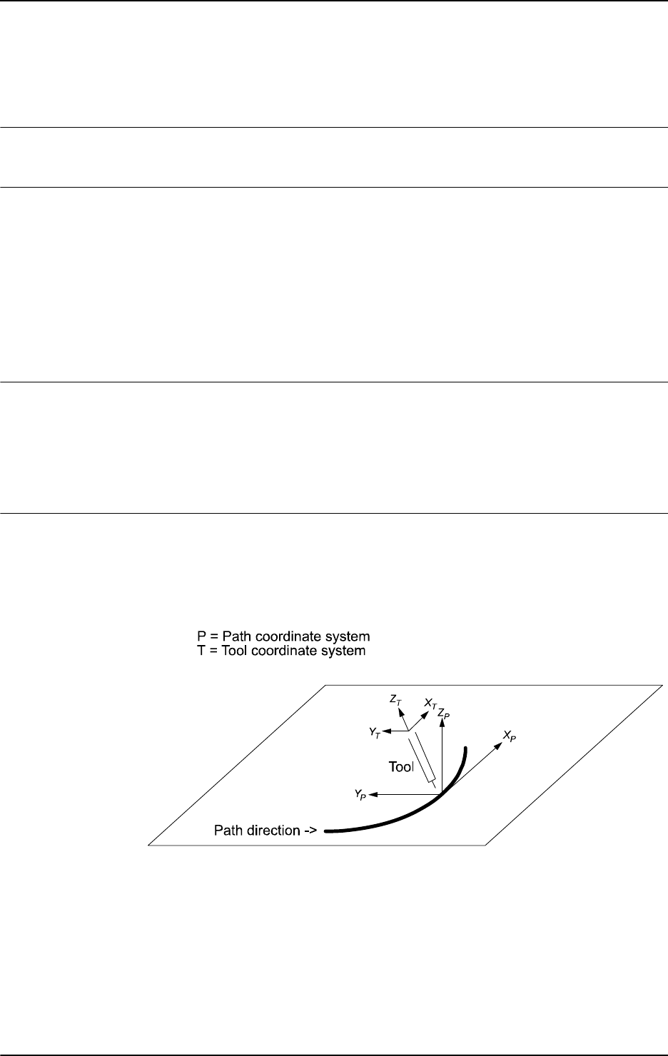
1 Instructions
1.31. CorrCon - Connects to a correction generator
Path Offset
713HAC 16581-1 Revision: J
© Copyright 2004-2010 ABB. All rights reserved.
1.31. CorrCon - Connects to a correction generator
Usage
CorrCon is used to connect to a correction generator.
Basic examples
A basic example of the instruction
CorrCon is illustrated below.
See also More examples on page 71.
Example1
VAR corrdescr id;
...
CorrCon id;
The correction generator reference corresponds to the variable id reservation.
Arguments
CorrCon Descr
Descr
Data type: corrdescr
Descriptor of the correction generator.
More examples
More examples of the instruction
CorrCon are illustrated below.
Path coordinate system
All path corrections (offsets on the path) are added in the path coordinate system. The path
coordinate system is defined as illustrated below:
xx0500002156
• Path coordinate axis X is given as the tangent of the path.
• Path coordinate axis Y is derived as the cross product of tool coordinate axis Z and
path coordinate axis X.
• Path coordinate axis Z is derived as the cross product of path coordinate axis X and
path coordinate axis Y.
Continues on next page
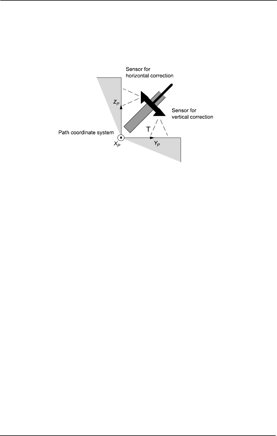
1 Instructions
1.31. CorrCon - Connects to a correction generator
Path Offset
3HAC 16581-1 Revision: J72
© Copyright 2004-2010 ABB. All rights reserved.
Application example
An example of an application using path corrections is a robot holding a tool with two sensors
mounted on it to detect the vertical and horizontal distances to a work object. The figure
below illustrates a path correction device.
xx0500002155
Program example
NOTE! hori_sig and vert_sig are analog signals defined in system
parameters.
CONST num TARGET_DIST := 5;
CONST num SCALE_FACTOR := 0.5;
VAR intnum intno1;
VAR corrdescr hori_id;
VAR corrdescr vert_id;
VAR pos total_offset;
VAR pos write_offset;
VAR bool conFlag;
PROC PathRoutine()
! Connect to the correction generators for horizontal and
vertical correction.
CorrCon hori_id;
CorrCon vert_id;
conFlag := TRUE;
! Setup a 5 Hz timer interrupt. The trap routine will read the
sensor values and
! compute the path corrections.
CONNECT intno1 WITH ReadSensors;
ITimer\Single, 0.2, intno1;
! Position for start of contour tracking
MoveJ p10,v100,z10,tool1;
! Run MoveL with both vertical and horizontal correction.
MoveL p20,v100,z10,tool1\Corr;
Continued
Continues on next page

1 Instructions
1.31. CorrCon - Connects to a correction generator
Path Offset
733HAC 16581-1 Revision: J
© Copyright 2004-2010 ABB. All rights reserved.
! Read the total corrections added by all connected correction
generators.
total_offset := CorrRead();
! Write the total vertical correction on the FlexPendant.
TPWrite "The total vertical correction is:"
\Num:=total_offset.z;
! Disconnect the correction generator for vertical correction.
! Horizontal corrections will be unaffected.
CorrDiscon vert_id;
conFlag := FALSE;
! Run MoveL with only horizontal interrupt correction.
MoveL p30,v100,z10,tool1\Corr;
! Remove all outstanding connected correction generators.
! In this case, the only connected correction generator is the
one for horizontal
! correction.
CorrClear;
! Remove the timer interrupt.
IDelete intno1;
ENDPROC
TRAP ReadSensors
VAR num horiSig;
VAR num vertSig;
! Compute the horizontal correction values and execute the
correction.
horiSig := hori_sig;
write_offset.x := 0;
write_offset.y := (hori_sig - TARGET_DIST)*SCALE_FACTOR;
write_offset.z := 0;
CorrWrite hori_id, write_offset;
IF conFlag THEN
! Compute the vertical correction values and execute the
correction.
write_offset.x := 0;
write_offset.y := 0;
write_offset.z := (vert_sig - TARGET_DIST)*SCALE_FACTOR;
CorrWrite vert_id, write_offset;
ENDIF
!Setup interrupt again
IDelete intnol;
CONNECT intno1 WITH ReadSensors;
ITimer\single, 0.2, intno1;
ENDTRAP
Continued
Continues on next page
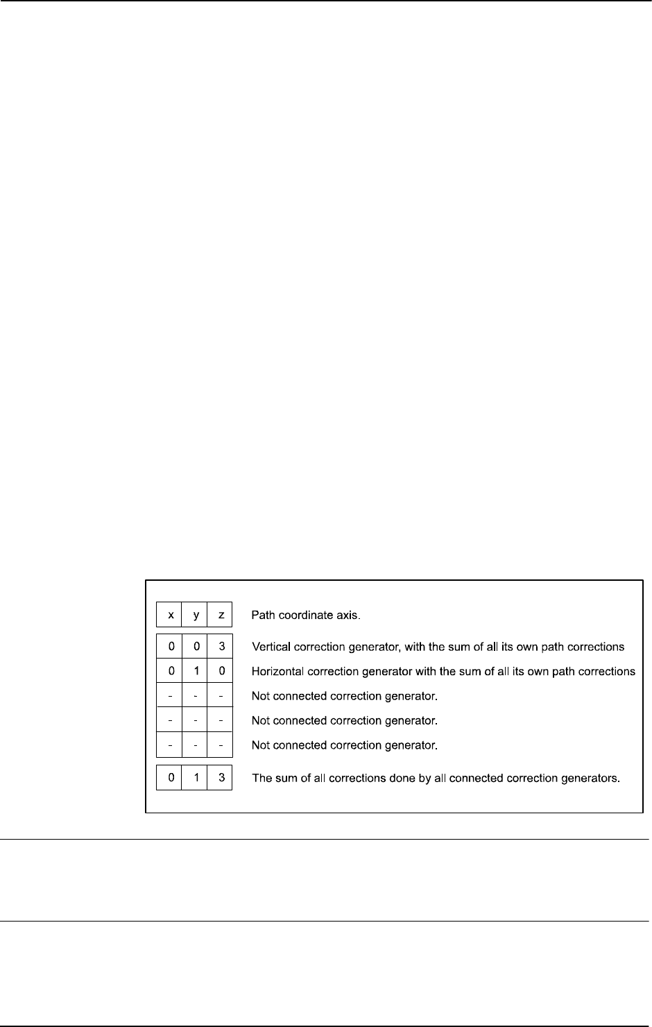
1 Instructions
1.31. CorrCon - Connects to a correction generator
Path Offset
3HAC 16581-1 Revision: J74
© Copyright 2004-2010 ABB. All rights reserved.
Program explanation
Two correction generators are connected with the instruction CorrCon. Each correction
generator is referenced by a unique descriptor (
hori_id and vert_id) of the type
corrdescr. The two sensors will use one correction generator each.
A timer interrupt is set up to call the trap routine
ReadSensors with a frequency of 5 Hz.
The offsets, needed for path correction, are computed in the trap routine and written to the
corresponding correction generator (referenced by the descriptors
hori_id and vert_id)
by the instruction
CorrWrite. All the corrections will have immediate effect on the path.
The
MoveL instruction must be programmed with the switch argument Corr when path
corrections are used. Otherwise, no corrections will be executed.
When the first
MoveL instruction is ready, the function CorrRead is used to read the sum of
all the corrections (the total path correction) given by all the connected correction generators.
The result of the total vertical path correction is written to the FlexPendant with the
instruction
TPWrite.
CorrDiscon will then disconnect the correction generator for vertical correction (referenced
by the descriptor
vert_id). All corrections added by this correction generator will be
removed from the total path correction. The corrections added by the correction generator for
horizontal correction will still be preserved.
Finally, the function
CorrClear will remove all remaining connected correction generators
and their previously added corrections. In this case, it is only the correction generator for
horizontal correction that will be removed. The timer interrupt will also be removed by the
instruction
IDelete.
The correction generators
The figure below illustrates the correction generators.
xx0500002160
Limitations
A maximum number of 5 correction generators can be connected simultaneously.
Connected Correction Generators do not survive a controller restart.
Syntax
CorrCon
[ Descr ':=' ] < variable (VAR) of corrdescr > ';'
Continued
Continues on next page

1 Instructions
1.31. CorrCon - Connects to a correction generator
Path Offset
753HAC 16581-1 Revision: J
© Copyright 2004-2010 ABB. All rights reserved.
Related information
For information about See
Disconnects from a correction generator CorrDiscon - Disconnects from a correction
generator on page 76
Writes to a correction generator CorrWrite - Writes to a correction generator
on page 77
Reads the current total offsets CorrRead - Reads the current total offsets
on page 803
Removes all correction generators CorrClear - Removes all correction
generators on page 70
Correction generator descriptor corrdescr - Correction generator descriptor
on page 1099
Continued

1 Instructions
1.32. CorrDiscon - Disconnects from a correction generator
Path Offset
3HAC 16581-1 Revision: J76
© Copyright 2004-2010 ABB. All rights reserved.
1.32. CorrDiscon - Disconnects from a correction generator
Description
CorrDiscon is used to disconnect from a previously connected correction generator. The
instruction can be used to remove corrections given earlier.
Basic examples
A basic example of the instruction
CorrDiscon is illustrated below.
See also More examples on page 76.
Example 1
VAR corrdescr id;
...
CorrCon id;
...
CorrDiscon id;
CorrDiscon
disconnects from the previously connected correction generator referenced by
the descriptor id.
Arguments
CorrDiscon Descr
Descr
Data type: corrdescr
Descriptor of the correction generator.
More examples
For more examples of the instruction CorrDiscon, see CorrCon - Connects to a correction
generator on page 71.
Syntax
CorrDiscon
[ Descr ':=' ] < variable (VAR) of corrdescr > ';'
Related information
For information about See
Connects to a correction generator CorrCon - Connects to a correction generator on
page 71
Writes to a correction generator CorrWrite - Writes to a correction generator on
page 77
Reads the current total offsets CorrRead - Reads the current total offsets on
page 803
Removes all correction generators CorrClear - Removes all correction generators on
page 70
Correction descriptor corrdescr - Correction generator descriptor on
page 1099

1 Instructions
1.33. CorrWrite - Writes to a correction generator
Path Offset
773HAC 16581-1 Revision: J
© Copyright 2004-2010 ABB. All rights reserved.
1.33. CorrWrite - Writes to a correction generator
Description
CorrWrite is used to write offsets in the path coordinate system to a correction generator.
Basic examples
A basic example of the instruction
CorrWrite is illustrated below.
Example 1
VAR corrdescr id;
VAR pos offset;
...
CorrWrite id, offset;
The current offsets, stored in the variable offset, are written to the correction generator
referenced by the descriptor id.
Arguments
CorrWrite Descr Data
Descr
Data type: corrdescr
Descriptor of the correction generator.
Data
Data type: pos
The offset to be written.
More examples
For more examples of the instruction CorrWrite, see CorrCon - Connects to a correction
generator on page 71.
Limitations
The best performance is achieved on straight paths. As the speed and angles between
consecutive linear paths increase, the deviation from the expected path will also increase. The
same applies to circles with decreasing circle radius.
Syntax
CorrWrite
[ Descr ':=' ] < variable (VAR) of corrdescr > ','
[ Data ':=' ] < expression (IN) of pos > ';'
Continues on next page

1 Instructions
1.33. CorrWrite - Writes to a correction generator
Path Offset
3HAC 16581-1 Revision: J78
© Copyright 2004-2010 ABB. All rights reserved.
Related information
For information about See
Connects to a correction generator CorrCon - Connects to a correction generator on
page 71
Disconnects from a correction generator CorrDiscon - Disconnects from a correction
generator on page 76
Reads the current total offsets CorrRead - Reads the current total offsets on
page 803
Removes all correction generators CorrClear - Removes all correction generators
on page 70
Correction generator descriptor corrdescr - Correction generator descriptor on
page 1099
Continued

1 Instructions
1.34. DeactUnit - Deactivates a mechanical unit
RobotWare - OS
793HAC 16581-1 Revision: J
© Copyright 2004-2010 ABB. All rights reserved.
1.34. DeactUnit - Deactivates a mechanical unit
Usage
DeactUnit is used to deactivate a mechanical unit.
It can be used to determine which unit is to be active when, for example, common drive units
are used.
This instruction can only be used in the main task
T_ROB1 or, if in a MultiMove system, in
Motion tasks.
Examples
Basic examples of the instruction
DeactUnit are illustrated below.
Example 1
DeactUnit orbit_a;
Deactivation of the orbit_a mechanical unit.
Example 2
MoveL p10, v100, fine, tool1;
DeactUnit track_motion;
MoveL p20, v100, z10, tool1;
MoveL p30, v100, fine, tool1;
ActUnit track_motion;
MoveL p40, v100, z10, tool1;
The unit track_motion will be stationary when the robot moves to p20 and p30. After this,
both the robot and
track_motion will move to p40.
Example 3
MoveL p10, v100, fine, tool1;
DeactUnit orbit1;
ActUnit orbit2;
MoveL p20, v100, z10, tool1;
The unit orbit1 is deactivated and orbit2 is activated.
Arguments
DeactUnit MechUnit
MechUnit
Mechanical Unit
Data type:
mecunit
The name of the mechanical unit that is to be deactivated.
Program execution
When the robot’s and external axes’ actual path is ready, the path on current path level is
cleared and the specified mechanical unit is deactivated. This means that it will neither be
controlled nor monitored until it is re-activated.
If several mechanical units share a common drive unit, deactivation of one of the mechanical
units will also disconnect that unit from the common drive unit.
Continues on next page

1 Instructions
1.34. DeactUnit - Deactivates a mechanical unit
RobotWare - OS
3HAC 16581-1 Revision: J80
© Copyright 2004-2010 ABB. All rights reserved.
Limitations
Instruction
DeactUnit cannot be used when one of the mechanical unit is in independent
mode.
If this instruction is preceded by a move instruction, that move instruction must be
programmed with a stop point (zonedata
fine), not a fly-by point, otherwise restart after
power failure will not be possible.
DeactUnit cannot be executed in a RAPID routine connected to any of following special
system events: PowerOn, Stop, QStop, Restart or Step.
It is possible to use
ActUnit - DeactUnit on StorePath level, but the same mechanical
units must be active when doing
RestoPath as when StorePath was done. If such
operation the Path Recorder and the path on the base level will be intact, but the path on the
StorePath level will be cleared.
Syntax
DeactUnit
[MechUnit ':='] < variable (VAR) of mecunit> ';'
Related information
For information about See
Activating mechanical units ActUnit - Activates a mechanical unit on page 17
Mechanical units mecunit - Mechanical unit on page 1139
Path Recorder PathRecMoveBwd - Move path recorder
backwards on page 298
mecunit - Mechanical unit on page 1139
Continued

1 Instructions
1.35. Decr - Decrements by 1
RobotWare - OS
813HAC 16581-1 Revision: J
© Copyright 2004-2010 ABB. All rights reserved.
1.35. Decr - Decrements by 1
Usage
Decr is used to subtract 1 from a numeric variable or persistent.
Basic examples
A basic example of the instruction
Decr is illustrated below.
See also More examples on page 81.
Example 1
Decr reg1;
1
is subtracted from reg1, that is reg1:=reg1-1.
Arguments
Decr Name | Dname
Name
Data type: num
The name of the variable or persistent to be decremented.
Dname
Data type: dnum
The name of the variable or persistent to be decremented.
More examples
More examples of the instruction
Decr are illustrated below.
Example 1
VAR num no_of_parts:=0;
...
TPReadNum no_of_parts, "How many parts should be produced? ";
WHILE no_of_parts>0 DO
produce_part;
Decr no_of_parts;
ENDWHILE
The operator is asked to input the number of parts to be produced. The variable
no_of_parts is used to count the number that still have to be produced.
Example 2
VAR dnum no_of_parts:=0;
...
TPReadDnum no_of_parts, "How many parts should be produced? ";
WHILE no_of_parts>0 DO
produce_part;
Decr no_of_parts;
ENDWHILE
The operator is asked to input the number of parts to be produced. The variable
no_of_parts is used to count the number that still have to be produced.
Continues on next page

1 Instructions
1.35. Decr - Decrements by 1
RobotWare - OS
3HAC 16581-1 Revision: J82
© Copyright 2004-2010 ABB. All rights reserved.
Syntax
Decr
[ Name ':=' ] < var or pers (INOUT) of num >
| [ Dname ':=' ] < var or pers (INOUT) of dnum >' ;'
Related information
For information about See
Incrementing a variable by 1 Incr - Increments by 1 on page 131
Subtracting any value from a variable Add - Adds a numeric value on page 19
Changing data using an arbitrary
expression, e.g. multiplication
":=" - Assigns a value on page 24
Continued

1 Instructions
1.36. DitherAct - Enables dither for soft servo
RobotWare - OS
833HAC 16581-1 Revision: J
© Copyright 2004-2010 ABB. All rights reserved.
1.36. DitherAct - Enables dither for soft servo
Usage
DitherAct is used to enable the dither functionality, which will reduce the friction in soft
servo for IRB 7600.
This instruction can only be used in the main task
T_ROB1 or, if in a MultiMove system, in
Motion tasks.
Basic examples
Basic examples of the instruction
DitherAct are illustrated below.
Example 1
SoftAct \MechUnit:=ROB_1, 2, 100;
WaitTime 2;
DitherAct \MechUnit:=ROB_1, 2;
WaitTime 1;
DitherDeact;
SoftDeact;
Dither is enabled only for one second while in soft servo.
Example 2
DitherAct \MechUnit:=ROB_1, 2;
SoftAct \MechUnit:=ROB_1, 2, 100;
WaitTime 1;
MoveL p1, v50, z20, tool1;
SoftDeact;
DitherDeact;
Dither is enabled for axis 2. Movement is delayed for one second to allow sufficient transition
time for the
SoftAct ramp. If DitherAct is called before SoftAct, dither will start
whenever a
SoftAct is executed for that axis. If no DitherDeact is called, dither will stay
enabled for all subsequent
SoftAct calls.
Arguments
DitherAct [\MechUnit] Axis [\Level]
[ \MechUnit ]
Mechanical Unit
Data type:
mecunit
The name of the mechanical unit. If argument is omitted, it means activation of the soft servo
for specified robot axis.
Axis
Data type: num
Axis number (1-6).
Continues on next page

1 Instructions
1.36. DitherAct - Enables dither for soft servo
RobotWare - OS
3HAC 16581-1 Revision: J84
© Copyright 2004-2010 ABB. All rights reserved.
[ \Level ]
Data type: num
Amplitude of dither (50-150%). At 50%, oscillations are reduced (increased friction). At
150%, amplitude is maximum (may result in vibrations of endeffector). The default value is
100%.
Program execution
DitherAct can be called before, or after SoftAct. Calling DitherAct after SoftAct is
faster but it has other limitations.
Dither is usually not required for axis 1 of IRB 7600. Highest effect of friction reduction is
on axes 2 and 3.
Dither parameters are self-adjusting. Full dither performance is achieved after three or four
executions of
SoftAct in process position.
Limitations
Calling
DitherAct after SoftAct may cause unwanted movement of the robot. The only
way to eliminate this behavior is to call
DitherAct before SoftAct. If there still is
movement,
SoftAct ramp time should be increased.
The transition time is the ramp time, which varies between robots, multiplied with the ramp
factor of the
SoftAct-instruction.
Dithering is not available for axis 6.
Dither is always deactivated when there is a power failure.
The instruction is only to be used for IRB 7600.
WARNING!
When calling
DitherAct before SoftAct the robot must be in a fine point. Also, leaving
the fine point is not permitted until the transition time of the ramp is over. This might
damage the gear boxes.
Syntax
DitherAct
[ '\' MechUnit ':=' < variable (VAR) of mecunit > ]
[Axis ':=' ] < expression (IN) of num >
[ '\' Level ':=' < expression (IN) of num > ] ';'
Related information
For information about See
Activating Soft Servo SoftAct - Activating the soft servo on page 473
Behavior with the soft servo engaged Technical reference manual - RAPID overview
Disable of dither DitherDeact - Disables dither for soft servo on
page 85
Continued

1 Instructions
1.37. DitherDeact - Disables dither for soft servo
RobotWare - OS
853HAC 16581-1 Revision: J
© Copyright 2004-2010 ABB. All rights reserved.
1.37. DitherDeact - Disables dither for soft servo
Usage
DitherDeact is used to disable the dither functionality for soft servo of IRB 7600.
This instruction can only be used in the main task
T_ROB1 or, if in a MultiMove system, in
Motion tasks.
Basic examples
A basic example of the instruction
DitherDeact is illustrated below.
Example 1
DitherDeact;
Deactivates dither on all axis.
Program execution
DitherDeact can be used at any time. If in soft servo, dither stops immediately on all axes.
If not in soft servo, dither will not be active when next
SoftAct is executed.
The dither is automatically disabled
• at a cold start-up
• when a new program is loaded
• when starting program execution from the beginning.
Syntax
DitherDeact';'
Related information
For information about See
Activating dither DitherAct - Enables dither for soft servo on page
83

1 Instructions
1.38. DropWObj - Drop work object on conveyor
Conveyor Tracking
3HAC 16581-1 Revision: J86
© Copyright 2004-2010 ABB. All rights reserved.
1.38. DropWObj - Drop work object on conveyor
Usage
DropWObj (Drop Work Object) is used to disconnect from the current object and the program
is ready for the next object on the conveyor.
Basic examples
A basic example of the instruction
DropWObj is illustrated below.
Example 1
MoveL *, v1000, z10, tool, \WObj:=wobj_on_cnv1;
MoveL *, v1000, fine, tool, \WObj:=wobj0;
DropWObj wobj_on_cnv1;
MoveL *, v1000, z10, tool, \WObj:=wobj0;
Arguments
DropWObj WObj
WObj
Work Object
Data type:
wobjdata
The moving work object (coordinate system) to which the robot position in the instruction is
related. The mechanical unit conveyor is to be specified by the
ufmec in the work object.
Program execution
Dropping the work object means that the encoder unit no longer tracks the object. The object
is removed from the object queue and cannot be recovered.
Limitations
If the instruction is issued while the robot is actively using the conveyor coordinated work
object, then the motion stops.
The instruction may be issued only after a fixed work object has been used in the preceding
motion instructions with either a fine point or several (>1) corner zones.
Syntax
DropWObj
[ WObj ':='] < persistent (PERS) of wobjdata>';'
Related information
For information about See
Wait for work objects WaitWObj - Wait for work object on conveyor on
page 701
Conveyor tracking Application manual - Conveyor tracking

1 Instructions
1.39. EOffsOff - Deactivates an offset for external axes
RobotWare - OS
873HAC 16581-1 Revision: J
© Copyright 2004-2010 ABB. All rights reserved.
1.39. EOffsOff - Deactivates an offset for external axes
Usage
EOffsOff (External Offset Off) is used to deactivate an offset for external axes.
The offset for external axes is activated by the instruction
EOffsSet or EOffsOn and applies
to all movements until some other offset for external axes is activated or until the offset for
external axes is deactivated.
This instruction can only be used in the main task
T_ROB1 or, if in a MultiMove system, in
Motion tasks.
Basic examples
Basic examples of the instruction
EOffsOff are illustrated below.
Example 1
EOffsOff;
Deactivation of the offset for external axes.
Example 2
MoveL p10, v500, z10, tool1;
EOffsOn \ExeP:=p10, p11;
MoveL p20, v500, z10, tool1;
MoveL p30, v500, z10, tool1;
EOffsOff;
MoveL p40, v500, z10, tool1;
An offset is defined as the difference between the position of each axis at p10 and p11. This
displacement affects the movement to
p20 and p30, but not to p40.
Program execution
Active offsets for external axes are reset.
Syntax
EOffsOff ';'
Related information
For information about See
Definition of offset using two positions EOffsOn - Activates an offset for external axes on
page 88
Definition of offset using known values EOffsSet - Activates an offset for external axes
using known values on page 90
Deactivation of the robot’s program dis-
placement
PDispOff - Deactivates program displacement on
page 316

1 Instructions
1.40. EOffsOn - Activates an offset for external axes
RobotWare - OS
3HAC 16581-1 Revision: J88
© Copyright 2004-2010 ABB. All rights reserved.
1.40. EOffsOn - Activates an offset for external axes
Usage
EOffsOn (External Offset On) is used to define and activate an offset for external axes using
two positions.
This instruction can only be used in the main task
T_ROB1 or, if in a MultiMove system, in
Motion tasks.
Basic examples
Basic examples of the instruction
EOffsOn are illustrated below.
See also More examples on page 89.
Example 1
MoveL p10, v500, z10, tool1;
EOffsOn \ExeP:=p10, p20;
Activation of an offset for external axes. This is calculated for each axis based on the
difference between positions
p10 and p20.
Example 2
MoveL p10, v500, fine \Inpos := inpos50, tool1;
EOffsOn *;
Activation of an offset for external axes. Since a stop point that is accurately defined has been
used in the previous instruction, the argument
\ExeP does not have to be used. The
displacement is calculated on the basis of the difference between the actual position of each
axis and the programmed point (*) stored in the instruction.
Arguments
EOffsOn [\ExeP] ProgPoint
[ \ExeP ]
Executed Point
Data type:
robtarget
The new position, used for calculation of the offset. If this argument is omitted, the current
position of the axes at the time of the program execution is used.
ProgPoint
Programmed Point
Data type:
robtarget
The original position of the axes at the time of programming.
Continues on next page

1 Instructions
1.40. EOffsOn - Activates an offset for external axes
RobotWare - OS
893HAC 16581-1 Revision: J
© Copyright 2004-2010 ABB. All rights reserved.
Program execution
The offset is calculated as the difference between
\ExeP and ProgPoint for each separate
external axis. If
\ExeP has not been specified, the current position of the axes at the time of
the program execution is used instead. Since it is the actual position of the axes that is used,
the axes should not move when
EOffsOn is executed.
This offset is then used to displace the position of external axes in subsequent positioning
instructions and remains active until some other offset is activated (the instruction
EOffsSet
or
EOffsOn) or until the offset for external axes is deactivated (the instruction EOffsOff).
Only one offset for each individual external axis can be activated at the same time. Several
EOffsOn, on the other hand, can be programmed one after the other and, if they are, the
different offsets will be added.
The external axes offset is automatically reset:
• At a cold start-up.
• When a new program is loaded.
• When starting program execution from the beginning.
More examples
More examples of how to use the instruction
EOffsOn are illustrated below.
Example 1
SearchL sen1, psearch, p10, v100, tool1;
PDispOn \ExeP:=psearch, *, tool1;
EOffsOn \ExeP:=psearch, *;
A search is carried out in which the searched position of both the robot and the external axes
is stored in the position
psearch. Any movement carried out after this starts from this
position using a program displacement of both the robot and the external axes. This is
calculated based on the difference between the searched position and the programmed point
(*) stored in the instruction.
Syntax
EOffsOn
[ '\' ExeP ':=' < expression (IN) of robtarget> ',']
[ ProgPoint ':=' ] < expression (IN) of robtarget> ';'
Related information
For information about See
Deactivation of offset for external axes EOffsOff - Deactivates an offset for external
axes on page 87
Definition of offset using known values EOffsSet - Activates an offset for external axes
using known values on page 90
Displacement of the robot’s movements PDispOn - Activates program displacement on
page 317
Coordinate systems Technical reference manual - RAPID overview
Continued
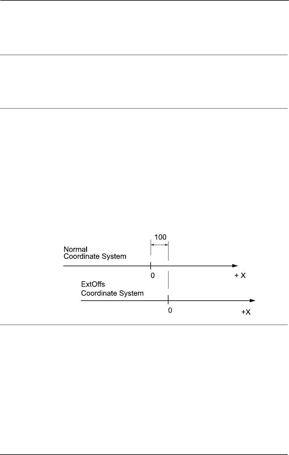
1 Instructions
1.41. EOffsSet - Activates an offset for external axes using known values
RobotWare - OS
3HAC 16581-1 Revision: J90
© Copyright 2004-2010 ABB. All rights reserved.
1.41. EOffsSet - Activates an offset for external axes using known values
Usage
EOffsSet (External Offset Set) is used to define and activate an offset for external axes using
known values.
This instruction can only be used in the main task
T_ROB1 or, if in a MultiMove system, in
Motion tasks.
Basic examples
A basic example of the instruction
EOffsSet is illustrated below.
Example 1
VAR extjoint eax_a_p100 := [100, 0, 0, 0, 0, 0];
...
EOffsSet eax_a_p100;
Activation of an offset eax_a_p100 for external axes, meaning (provided that the logical
external axis "a" is linear) that:
• The ExtOffs coordinate system is displaced 100 mm for the logical axis "a" (see
figure below).
• As long as this offset is active, all positions will be displaced 100 mm in the direction
of the x-axis.
The figure shows displacement of an external axis.
xx0500002162
Arguments
EOffsSet EAxOffs
EAxOffs
External Axes Offset
Data type:
extjoint
The offset for external axes is defined as data of the type extjoint, expressed in:
• mm for linear axes
• degrees for rotating axes
Continues on next page

1 Instructions
1.41. EOffsSet - Activates an offset for external axes using known values
RobotWare - OS
913HAC 16581-1 Revision: J
© Copyright 2004-2010 ABB. All rights reserved.
Program execution
The offset for external axes is activated when the
EOffsSet instruction is executed and
remains active until some other offset is activated (the instruction
EOffsSet or EOffsOn) or
until the offset for external axes is deactivated (the instruction
EOffsOff).
Only one offset for external axes can be activated at the same time. Offsets cannot be added
to one another using
EOffsSet.
The external axes offset is automatically reset:
• At a cold start-up.
• When a new program is loaded.
• When starting program executing from the beginning.
Syntax
EOffsSet
[ EAxOffs ':=' ] < expression (IN) of extjoint> ';'
Related information
For information about See
Activate an offset for external axes EOffsOn - Activates an offset for external axes
on page 88
Deactivation of offset for external axes EOffsOff - Deactivates an offset for external
axes on page 87
Displacement of the robot’s movements PDispOn - Activates program displacement on
page 317
Definition of data of the type extjoint extjoint - Position of external joints on page 1118
Coordinate systems Technical reference manual - RAPID overview
Continued

1 Instructions
1.42. EraseModule - Erase a module
RobotWare - OS
3HAC 16581-1 Revision: J92
© Copyright 2004-2010 ABB. All rights reserved.
1.42. EraseModule - Erase a module
Usage
EraseModule is used to remove a module from the program memory during execution.
There are no restrictions on how the module was loaded. It could have been loaded manually,
from the configuration, or with a combination of the instructions
Load, StartLoad, and
WaitLoad.
The module cannot be defined as Shared in the configuration.
Basic examples
A basic example of the instruction
EraseModule is illustrated below.
Example 1
EraseModule "PART_A";
Erase the program module PART_A from the program memory.
Arguments
EraseModule ModuleName
ModuleName
Data type: string
The name of the module that should be removed. Please note that this is the name of the
module, not the name of the file.
Program execution
The program execution waits for the program module to finish the removal process before the
execution proceeds with the next instruction.
When the program module is removed the rest of the program modules will be linked.
Limitations
It is not allowed to remove a program module that is executing.
TRAP routines, system I/O events, and other program tasks cannot execute during the
removal process.
Avoid ongoing robot movements during the removal.
Program stop during execution of
EraseModule instruction results in guard stop with motors
off and error message "20025 Stop order timeout" on the FlexPendant.
Error handling
If the file in the
EraseModule instruction cannot be removed because it was not found, the
system variable ERRNO is set to ERR_MODULE. This error can then be handled in the error
handler.
Syntax
EraseModule
[ModuleName':=']<expression (IN) of string>';'
Continues on next page

1 Instructions
1.42. EraseModule - Erase a module
RobotWare - OS
933HAC 16581-1 Revision: J
© Copyright 2004-2010 ABB. All rights reserved.
Related information
For information about See
Unload a program module UnLoad - UnLoad a program module during
execution on page 655
Load a program module in parallel with
another program execution
StartLoad - Load a program module during
execution on page 482
WaitLoad - Connect the loaded module to the task
on page 682
Accept unresolved reference Technical reference manual - System parameters,
section Controller
Continued

1 Instructions
1.43. ErrLog - Write an error message
RobotWare - OS
3HAC 16581-1 Revision: J94
© Copyright 2004-2010 ABB. All rights reserved.
1.43. ErrLog - Write an error message
Usage
ErrLog is used to display an error message on the FlexPendant and write it in the event log.
Error number and five error arguments must be stated. The message is stored in the process
domain in the robot log.
ErrLog can also be used to display warnings and information
messages.
Basic examples
Basic examples of the instruction
ErrLog are illustrated below.
Example 1
In case you do not want to make your own .xml file, you can use ErrorId 4800 like in the
example below:
VAR errstr my_title := "myerror";
VAR errstr str1 := "errortext1";
VAR errstr str2 := "errortext2";
VAR errstr str3 := "errortext3";
VAR errstr str4 := "errortext4";
ErrLog 4800, my_title, str1,str2,str3,str4;
On the FlexPendant the message will look like this:
Event Message: 4800
myerror
errortext1
errortext2
errortext3
errortext4
Example 2
An ErrorId must be declared in an .xml file. The number must be between 5000 - 9999. The
error message is written in the .xml file and the arguments to the message is sent in by the
ErrLog instruction. The ErrorId in the .xml file is the same stated in the ErrLog
instruction.
NOTE: If using an ErrorId between 5000-9999 you have to install your own xml file.
Example of message in .xml file:
<Message number="5210" eDefine="ERR_INPAR_RDONLY">
<Title>Parameter error</Title>
<Description>Task:<arg format="%s" ordinal="1" />
<p />Symbol <arg format="%s" ordinal="2" />is read-only
<p />Context:<arg format="%s" ordinal="3" /><p />
</Description>
</Message>
Continues on next page

1 Instructions
1.43. ErrLog - Write an error message
RobotWare - OS
953HAC 16581-1 Revision: J
© Copyright 2004-2010 ABB. All rights reserved.
Example of instruction:
MODULE MyModule
PROC main()
VAR num errorid := 5210;
VAR errstr arg := "P1";
ErrLog errorid, ERRSTR_TASK, arg,
ERRSTR_CONTEXT,ERRSTR_UNUSED, ERRSTR_UNUSED;
ErrLog errorid \W, ERRSTR_TASK, arg,
ERRSTR_CONTEXT,ERRSTR_UNUSED, ERRSTR_UNUSED;
ENDPROC
ENDMODULE
On the FlexPendant the message will look like this:
Event Message: 5210
Parameter error
Task: T_ROB1
Symbol P1 is read-only.
Context: MyModule/main/ErrLog
The first
ErrLog instruction generates an error message. The message is stored in the robot
log in the process domain. It is also shown on the FlexPendant display.
The second instruction is a warning. A message is stored in the robot log only.
The program will in both cases continue its execution when the instruction is done.
Arguments
ErrLog ErrorID [\W] | [\I] Argument1 Argument2 Argument3 Argument4
Argument5
ErrorId
Data type: num
The number of a specific error that is to be monitored. The error number must be in interval
4800-4814 if using the preinstalled xml file, and between 5000 - 9999 if using an own xml
file.
[ \W ]
Warning
Data type:
switch
Gives a warning that is stored in the robot event log only (not shown directly on the
FlexPendant display).
[ \I ]
Information
Data type:
switch
Gives an information message that is stored in the event log only (not shown directly on the
FlexPendant display).
If none of the arguments
\W or \I are specified then the instruction will generate an error
message directly on the flexpendant and also store it in the event log.
Continued
Continues on next page

1 Instructions
1.43. ErrLog - Write an error message
RobotWare - OS
3HAC 16581-1 Revision: J96
© Copyright 2004-2010 ABB. All rights reserved.
Argument1
Data type: errstr
First argument in the error message. Any string or predefined data of type errstr can be
used.
Argument2
Data type: errstr
Second argument in the error message. Any string or predefined data of type errstr can be
used.
Argument3
Data type: errstr
Third argument in the error message. Any string or predefined data of type errstr can be
used
Argument4
Data type: errstr
Fourth argument in the error message. Any string or predefined data of type errstr can be
used.
Argument5
Data type: errstr
Fifth argument in the error message. Any string or predefined data of type errstr can be
used.
Program execution
An error message (max 5 lines) is displayed on the FlexPendant and written in the event log.
In the case of argument
\W or argument \I a warning or an information message is written
in the event log.
ErrLog generates program errors between 4800-4814 if using the xml file that are installed
by the system, and between 5000-9999 if installing an own xml file. The error generated
depends on the
ErrorID indicated.
The message is stored in the process domain in the event log.
How to install an own xml file is described in the Additional options manual, see Related
information below.
Limitations
Total string length (Argument1-Argument5) is limited to 195 characters.
Continued
Continues on next page

1 Instructions
1.43. ErrLog - Write an error message
RobotWare - OS
973HAC 16581-1 Revision: J
© Copyright 2004-2010 ABB. All rights reserved.
Syntax
ErrLog
[ErrorId ':=' ] < expression (IN) of num> ','
[ '\'W ] | [' \' I ] ','
[Argument1 ':=' ] < expression (IN) of errstr> ','
[Argument2 ':=' ] < expression (IN) of errstr> ','
[Argument3 ':=' ] < expression (IN) of errstr> ','
[Argument4 ':=' ] < expression (IN) of errstr> ','
[Argument5 ':=' ] < expression (IN) of errstr> ';'
Related information
For information about See
Predefined data of type errstr errstr - Error string on page 1114
Display message on the FlexPendant TPWrite - Writes on the FlexPendant on page
568
UIMsgBox - User Message Dialog Box type basic
on page 644
Event log Operating manual - IRC5 with FlexPendant
Event log messages, explanation of xml-
file
Application manual - Additional options, section
Event log messages
How to install XML files when using
additional options
Application manual - Additional options
Continued

1 Instructions
1.44. ErrRaise - Writes a warning and calls an error handler
RobotWare - OS
3HAC 16581-1 Revision: J98
© Copyright 2004-2010 ABB. All rights reserved.
1.44. ErrRaise - Writes a warning and calls an error handler
Usage
ErrRaise is used to create an error in the program and then call the error handler of the
routine. A warning is written in the event log.
ErrRaise can also be used in the error handler
to propagate the current error to the error handler of the calling routine.
Error name, error number, and five error arguments must be stated. The message is stored in
the process domain in the robot log.
Basic examples
Basic examples of the instruction
ErrRaise is illustrated below.
Example 1
In case you do not want to make your own .xml file, you can use ErrorId 4800 like in the
example below:
MODULE MyModule
VAR errnum ERR_BATT:=-1;
PROC main()
VAR num errorid := 4800;
VAR errstr my_title := "Backup battery status";
VAR errstr str1 := "Bacup battery is fully charged";
BookErrNo ERR_BATT;
ErrRaise "ERR_BATT", errorid, my_title, ERRSTR_TASK, str1,
ERRSTR_CONTEXT,ERRSTR_EMPTY;
ERROR
IF ERRNO = ERR_BATT THEN
TRYNEXT;
ENDIF
ENDPROC
ENDMODULE
On the FlexPendant the message will look like this (warning and/or an error):
Event Message: 4800
Backup battery status
Task: main
Backup battery is fully charged
Context: MyModule/main/ErrRaise
An error number must be booked with the instruction
BookErrNo. Corresponding string is
stated as the first argument,
ErrorName, in the ErrRaise.
ErrRaise creates an error and then calls the error handler. If the error is taken care of, a
warning is generated in the event log, in the process domain. Otherwise a fatal error is
generated and the program stops.
ErrRaise can also be used in an error handler in a subroutine. In this case the execution
continues in the error handler of the calling routine.
Continues on next page

1 Instructions
1.44. ErrRaise - Writes a warning and calls an error handler
RobotWare - OS
993HAC 16581-1 Revision: J
© Copyright 2004-2010 ABB. All rights reserved.
Example 2
An ErrorId must be declared in an .xml file. The number must be between 5000 - 9999. The
error message is written in the .xml file and the arguments to the message are sent in by the
ErrRaise instruction. The ErrorId in the .xml file is the same stated in the ErrRaise
instruction.
NOTE: If using an ErrorId between 5000-9999 you have to install your own xml file.
Example of message in .xml file:
<Message number="7055" eDefine="SYS_ERR_ARL_INPAR_RDONLY">
<Title>Parameter error</Title>
<Description>Task:<arg format="%s" ordinal="1" />
<p />Symbol <arg format="%s" ordinal="2" />is read-only
<p />Context:<arg format="%s" ordinal="3" /><p /></
Description>
</Message>
Example of instruction:
MODULE MyModule
VAR errnum ERR_BATT:=-1;
PROC main()
VAR num errorid := 7055;
BookErrNo ERR_BATT;
ErrRaise "ERR_BATT", errorid, ERRSTR_TASK,
ERRSTR_CONTEXT,ERRSTR_UNUSED, ERRSTR_UNUSED,
ERRSTR_UNUSED;
ERROR
IF ERRNO = ERR_BATT THEN
TRYNEXT;
ENDIF
ENDPROC
ENDMODULE
On the FlexPendant the message will look like this (warning and/or an error):
Event Message: 7055
Backup battery status
Task: main
Backup battery is fully charged
Context: MyModule/main/ErrRaise
An error number must be booked with the instruction
BookErrNo. Corresponding string is
stated as the first argument,
ErrorName, in the ErrRaise.
ErrRaise creates an error and then calls the error handler. If the error is taken care of, a
warning is generated in the event log, in the process domain. Otherwise a fatal error is
generated and the program stops.
ErrRaise can also be used in an error handler in a subroutine. In this case the execution
continues in the error handler of the calling routine.
Continued
Continues on next page

1 Instructions
1.44. ErrRaise - Writes a warning and calls an error handler
RobotWare - OS
3HAC 16581-1 Revision: J100
© Copyright 2004-2010 ABB. All rights reserved.
Arguments
ErrRaise ErrorName ErrorId Argument1 Argument2 Argument3 Argument4
Argument5
ErrorName
Data type: string
An error number must be booked using the instruction BookErrNo. Corresponding variable
is stated as
ErrorName.
ErrorId
Data type: num
The number of a specific error that is to be monitored. The error number must be in interval
4800-4814 if using the preinstalled xml file, and between 5000 - 9999 if using an own xml
file.
Argument1
Data type: errstr
First argument in the error message. Any string or predefined data of type errstr can be
used.
Argument2
Data type: errstr
Second argument in the error message. Any string or predefined data of type errstr can be
used.
Argument3
Data type: errstr
Third argument in the error message. Any string or predefined data of type errstr can be
used
Argument4
Data type: errstr
Fourth argument in the error message. Any string or predefined data of type errstr can be
used.
Argument5
Data type: errstr
Fifth argument in the error message. Any string or predefined data of type errstr can be
used.
Continued
Continues on next page

1 Instructions
1.44. ErrRaise - Writes a warning and calls an error handler
RobotWare - OS
1013HAC 16581-1 Revision: J
© Copyright 2004-2010 ABB. All rights reserved.
Program execution
ErrRaise generates program warningss between 4800-4814 if using the xml file that are
installed by the system, and between 5000-9999 if installing an own xml file. The error
generated depends on the
ErrorID indicated. A warning is written in the robot message log
in the domain process.
When the
ErrRaise is executed the behavior depends on where it is executed:
• When executing instruction in the routine body, a warning is generated, and the
execution continues in the error handler.
• When executing instruction in an error handler, the old warning is skipped, a new one
is generated, and the control is raised to calling instruction.
Limitations
Total string length (Argument1-Argument5) is limited to 195 characters.
More examples
More examples of how to use the instruction
ErrRaise are illustrated below.
Example 1
VAR errnum ERR_BATT:=-1;
VAR errnum ERR_NEW_ERR:=-1;
PROC main()
testerrraise;
ENDPROC
PROC testerrraise()
BookErrNo ERR_BATT;
BookErrNo ERR_NEW_ERR;
ErrRaise "ERR_BATT",7055,ERRSTR_TASK,ERRSTR_CONTEXT,
ERRSTR_UNUSED,ERRSTR_UNUSED,ERRSTR_UNUSED;
ERROR
IF ERRNO = ERR_BATT THEN
ErrRaise "ERR_NEW_ERR",7156,ERRSTR_TASK,ERRSTR_CONTEXT,
ERRSTR_UNUSED,ERRSTR_UNUSED, ERRSTR_UNUSED;
ENDIF
ENDPROC
Generate new warning 7156 from error handler. Raise control to calling routine and stop
execution.
Continued
Continues on next page

1 Instructions
1.44. ErrRaise - Writes a warning and calls an error handler
RobotWare - OS
3HAC 16581-1 Revision: J102
© Copyright 2004-2010 ABB. All rights reserved.
Syntax
ErrRaise
[ErrorName ':=' ] < expression (IN) of string> ','
[ErrorId ':=' ] < expression (IN) of num> ','
[Argument1 ':=' ] < expression (IN) of errstr> ','
[Argument2 ':=' ] < expression (IN) of errstr> ','
[Argument3 ':=' ] < expression (IN) of errstr> ','
[Argument4 ':=' ] < expression (IN) of errstr> ','
[Argument5 ':=' ] < expression (IN) of errstr> ';'
Related information
For information about See
Predefined data of type errstr errstr - Error string on page 1114
Booking error numbers BookErrNo - Book a RAPID system error number
on page 30
Error handling Technical reference manual - RAPID overview
Continued

1 Instructions
1.45. ErrWrite - Write an error message
RobotWare - OS
1033HAC 16581-1 Revision: J
© Copyright 2004-2010 ABB. All rights reserved.
1.45. ErrWrite - Write an error message
Usage
ErrWrite (Error Write) is used to display an error message on the FlexPendant and write it
in the event log. It can also be used to display warnings and information messages.
Basic examples
Basic examples of the instruction
ErrWrite are illustrated below.
Example 1
ErrWrite "PLC error", "Fatal error in PLC" \RL2:="Call service";
Stop;
A message is stored in the robot log. The message is also shown on the FlexPendant display.
Example 2
ErrWrite \W, "Search error", "No hit for the first search";
RAISE try_search_again;
A message is stored in the robot log only. Program execution then continues.
Arguments
ErrWrite [ \W ] | [\I] Header Reason [ \RL2] [ \RL3] [ \RL4]
[ \W ]
Warning
Data type:
switch
Gives a warning that is stored in the robot error message log only (not shown directly on the
FlexPendant display).
[ \I ]
Information
Data type:
switch
Gives an information message that is stored in the event log only (not shown directly on the
FlexPendant display).
If none of the arguments
\W or \I are specified then the instruction will generate an error
message directly on the flexpendant and also store it in the event log.
Header
Data type: string
Error message heading (max. 46 characters).
Reason
Data type: string
Reason for error.
[ \RL2]
Reason Line 2
Data type:
string
Reason for error.
Continues on next page

1 Instructions
1.45. ErrWrite - Write an error message
RobotWare - OS
3HAC 16581-1 Revision: J104
© Copyright 2004-2010 ABB. All rights reserved.
[ \RL3]
Reason Line 3
Data type:
string
Reason for error.
[ \RL4]
Reason Line 4
Data type:
string
Reason for error.
Program execution
An error message (max. 5 lines) is displayed on the FlexPendant and written in the robot
message log.
In the case of argument
\W or argument \I a warning or an information message is written
in the event log.
ErrWrite generates the program error no. 80001 for an error, no. 80002 for a warning (\W)
and no. 80003 for an information message
(\I).
Limitations
Total string length (Header+Reason+\RL2+\RL3+\RL4) is limited to 195 characters.
Syntax
ErrWrite
[ '\'W ] | [ '\' I ] ','
[ Header ':=' ] < expression (IN) of string>','
[ Reason ':=' ] < expression (IN) of string>
[ ’\’RL2 ':=' < expression (IN) of string> ]
[ ’\’RL3 ':=' < expression (IN) of string> ]
[ ’\’RL4 ':=' < expression (IN) of string> ] ';'
Related information
For information about See
Predefined data of type errstr errstr - Error string on page 1114
Display message on the FlexPendant TPWrite - Writes on the FlexPendant on page
568
UIMsgBox - User Message Dialog Box type basic
on page 644
Event log Operating manual - IRC5 with FlexPendant
Write error message - Err Log ErrLog - Write an error message on page 94
Continued

1 Instructions
1.46. EXIT - Terminates program execution
RobotWare - OS
1053HAC 16581-1 Revision: J
© Copyright 2004-2010 ABB. All rights reserved.
1.46. EXIT - Terminates program execution
Usage
EXIT is used to terminate program execution. Program restart will then be blocked, that is
the program can only be restarted from the first instruction of the main routine.
The
EXIT instruction should be used when fatal errors occur or when program execution is
to be stopped permanently. The
Stop instruction is used to temporarily stop program
execution. After execution of the instruction
EXIT the program pointer is gone. To continue
program execution, the program pointer must be set.
Basic examples
A basic example of the instruction
EXIT is illustrated below.
Example 1
ErrWrite "Fatal error","Illegal state";
EXIT;
Program execution stops and cannot be restarted from that position in the program.
Syntax
EXIT ';'
Related information
For information about See
Stopping program execution temporarily Stop - Stops program execution on page 510

1 Instructions
1.47. ExitCycle - Break current cycle and start next
RobotWare - OS
3HAC 16581-1 Revision: J106
© Copyright 2004-2010 ABB. All rights reserved.
1.47. ExitCycle - Break current cycle and start next
Usage
ExitCycle is used to break the current cycle and move the program pointer (PP) back to the
first instruction in the main routine.
If the program is executed in continuous mode, it will start to execute the next cycle.
If the execution is in cycle mode, the execution will stop at the first instruction in the main
routine.
Basic examples
Basic examples of the instruction
ExitCycle are illustrated below.
Example 1
VAR num cyclecount:=0;
VAR intnum error_intno;
PROC main()
IF cyclecount = 0 THEN
CONNECT error_intno WITH error_trap;
ISignalDI di_error,1,error_intno;
ENDIF
cyclecount:=cyclecount+1;
! start to do something intelligent
...
ENDPROC
TRAP error_trap
TPWrite "ERROR, I will start on the next item";
ExitCycle;
ENDTRAP
This will start the next cycle if the signal di_error is set.
Program execution
Execution of
ExitCycle in a program task controlling mechanical units results in the
following in the actual task:
• On-going robot movements stops.
• All robot paths that are not performed at all path levels (both normal and StorePath
level) are cleared.
• All instructions that are started but not finished at all execution levels (both normal
and
TRAP level) are interrupted.
• The program pointer is moved to the first instruction in the main routine.
• The program execution continues to execute the next cycle.
Continues on next page

1 Instructions
1.47. ExitCycle - Break current cycle and start next
RobotWare - OS
1073HAC 16581-1 Revision: J
© Copyright 2004-2010 ABB. All rights reserved.
Execution of ExitCycle in some other program task, not controlling mechanical units,
results in the following in the actual task:
• All instructions that are started but not finished on all execution levels (both normal
and
TRAP level) are interrupted.
• The program pointer is moved to the first instruction in the main routine.
• The program execution continues to execute the next cycle.
All other modal things in the program and system are not affected by
ExitCycle such as:
• The actual value of variables or persistents.
• Any motion settings such as StorePath-RestoPath sequence, world zones, etc.
• Open files, directories, etc.
• Defined interrupts, etc.
When using
ExitCycle in routine calls and the entry routine is defined with “Move PP to
Routine ...” or “Call Routine ...”,
ExitCycle breaks the current cycle and moves the program
pointer back to the first instruction in the entry routine (instead of the main routine as
specified above).
Syntax
ExitCycle';'
Related information
For information about See
Stopping after a fatal error EXIT - Terminates program execution on page
105
Terminating program execution EXIT - Terminates program execution on page
105
Stopping for program actions Stop - Stops program execution on page 510
Finishing execution of a routine RETURN - Finishes execution of a routine on
page 365
Continued

1 Instructions
1.48. FOR - Repeats a given number of times
RobotWare - OS
3HAC 16581-1 Revision: J108
© Copyright 2004-2010 ABB. All rights reserved.
1.48. FOR - Repeats a given number of times
Usage
FOR is used when one or several instructions are to be repeated a number of times.
Basic examples
A basic example of the instruction
FOR is illustrated below.
See also More examples on page 108.
Example 1
FOR i FROM 1 TO 10 DO
routine1;
ENDFOR
Repeats the routine1 procedure 10 times.
Arguments
FOR Loop counter FROM Start value TO End value [STEP Step value]
DO ... ENDFOR
Loop counter
Identifier
The name of the data that will contain the value of the current loop counter. The data is
declared automatically.
If the loop counter name is the same as any data that already exists in the actual scope, the
existing data will be hidden in the
FOR loop and not affected in any way.
Start value
Data type: Num
The desired start value of the loop counter. (usually integer values)
End value
Data type: Num
The desired end value of the loop counter. (usually integer values)
Step value
Data type: Num
The value by which the loop counter is to be incremented (or decremented) each loop.
(usually integer values)
If this value is not specified, the step value will automatically be set to 1 (or -1 if the start
value is greater than the end value).
More examples
More examples of how to use the instruction
FOR are illustrated below.
Example 1
FOR i FROM 10 TO 2 STEP -2 DO
a{i} := a{i-1};
ENDFOR
The values in an array are adjusted upwards so that a{10}:=a{9}, a{8}:=a{7} etc.
Continues on next page

1 Instructions
1.48. FOR - Repeats a given number of times
RobotWare - OS
1093HAC 16581-1 Revision: J
© Copyright 2004-2010 ABB. All rights reserved.
Program execution
1. The expressions for the start, end, and step values are evaluated.
2. The loop counter is assigned the start value.
3. The value of the loop counter is checked to see whether its value lies between the start
and end value, or whether it is equal to the start or end value. If the value of the loop
counter is outside of this range, the
FOR loop stops and program execution continues
with the instruction following
ENDFOR.
4. The instructions in the
FOR loop are executed.
5. The loop counter is incremented (or decremented) in accordance with the step value.
6. The
FOR loop is repeated, starting from point 3.
Limitations
The loop counter (of data type
num) can only be accessed from within the FOR loop and
consequently hides other data and routines that have the same name. It can only be read (not
updated) by the instructions in the
FOR loop.
Decimal values for start, end, or stop values, in combination with exact termination
conditions for the
FOR loop, cannot be used (undefined whether or not the last loop is
running).
Remarks
If the number of repetitions is to be repeated as long as a given expression is evaluated to a
TRUE value, the WHILE instructions should be used instead.
Syntax
(EBNF)
FOR <loop variable> FROM <expression> TO <expression>
[ STEP <expression> ] DO
<instruction list>
ENDFOR
<loop variable> ::= <identifier>
Related information
For information about See
Expressions Technical reference manual - RAPID overview
Repeats as long as... WHILE - Repeats as long as ... on page 705
Identifiers Technical reference manual - RAPID overview
Continued

1 Instructions
1.49. GetDataVal - Get the value of a data object
RobotWare - OS
3HAC 16581-1 Revision: J110
© Copyright 2004-2010 ABB. All rights reserved.
1.49. GetDataVal - Get the value of a data object
Usage
GetDataVal (Get Data Value) makes it possible to get a value from a data object that is
specified with a string variable.
Basic examples
Basic examples of the instruction
GetDataVal are illustrated below.
Example 1
VAR num value;
...
GetDataVal "reg"+ValToStr(ReadNum(mycom)),value;
This will get the value of a register, with a number which is received from the serial channel
mycom. The value will be stored in the variable value.
Example 2
VAR datapos block;
VAR string name;
VAR num valuevar;
...
SetDataSearch "num" \Object:="my.*" \InMod:="mymod";
WHILE GetNextSym(name,block) DO
GetDataVal name\Block:=block,valuevar;
TPWrite name+" "\Num:=valuevar;
ENDWHILE
This session will print out all num variables that begin with my in the module mymod with its
value to the FlexPendant.
Example 3
VAR num NumArrConst_copy{2};
...
GetDataVal "NumArrConst", NumArrConst_copy;
TPWrite "Pos1 = " \Num:=NumArrConst_copy{1};
TPWrite "Pos2 = " \Num:=NumArrConst_copy{2};
This session will print out the num variables in the array NumArrConst.
Arguments
GetDataVal Object [\Block]|[\TaskRef]|[\TaskName]Value
Object
Data type: string
The name of the data object.
Continues on next page

1 Instructions
1.49. GetDataVal - Get the value of a data object
RobotWare - OS
1113HAC 16581-1 Revision: J
© Copyright 2004-2010 ABB. All rights reserved.
[ \Block ]
Data type: datapos
The enclosed block to the data object. This can only be fetched with the GetNextSym
function.
If this argument is omitted, the value of the visible data object in the current program
execution scope will be fetched.
[\TaskRef]
Task Reference
Data type:
taskid
The program task identity in which to search for the data object specified. When using this
argument, you may search for
PERS or TASK PERS declarations in other tasks, any other
declarations will result in an error.
For all program tasks in the system the predefined variables of the data type
taskid will be
available. The variable identity will be "taskname"+"Id", e.g. for the
T_ROB1 task the variable
identity will be
T_ROB1Id.
[\TaskName]
Data type: string
The program task name in which to search for the data object specified. When using this
argument, you may search for
PERS or TASK PERS declarations in other tasks, any other
declarations will result in an error.
Value
Data type: anytype
Variable for storage of the get value. The data type must be the same as the data type for the
data object to find. The get value can be fetched from a constant, variable, or persistent but
must be stored in a variable.
Error handling
The system variable
ERRNO is set to ERR_SYM_ACCESS if:
• the data object is non-existent
• the data object is routine data or routine parameter and is not located in the current
active routine
• searching in other tasks for other declarations then PERS or TASK PERS
When using the arguments TaskRef or TaskName you may search for PERS or TASK PERS
declarations in other tasks, any other declarations will result in an error and the system
variable
ERRNO is set to ERR_SYM_ACCESS. Searching for a PERS declared as LOCAL in other
tasks will also result in an error and the system variable
ERRNO is set to ERR_SYM_ACCESS.
The system variable
ERRNO is set to ERR_INVDIM if the data object and the variable used in
argument
Value have different dimensions.
The error can be handled in the error handler of the routine.
Continued
Continues on next page

1 Instructions
1.49. GetDataVal - Get the value of a data object
RobotWare - OS
3HAC 16581-1 Revision: J112
© Copyright 2004-2010 ABB. All rights reserved.
Limitations
For a semivalue data type, it is not possible to search for the associated value data type. E.g.
if searching for
dionum, no search hit for signals signaldi will be obtained and if searching
for
num, no search hit for signals signalgi or signalai will be obtained.
It is not possible to get the value of a variable declared as
LOCAL in a built in RAPID module.
Syntax
GetDataVal
[ Object ’:=’ ] < expression (IN) of string >
[’\’Block’ :=’<variable (VAR) of datapos>]
|[ ’\’TaskRef’ :=’ <variable (VAR) of taskid>]
|[ ’\’TaskName’ :=’ <expression (IN) of string>] ’,’]
[ Value ’:=’ ] <variable (VAR) of anytype>]’;’
Related information
For information about See
Define a symbol set in a search
session
SetDataSearch - Define the symbol set in a search
sequence on page 433
Get next matching symbol GetNextSym - Get next matching symbol on page 855
Set the value of a data object SetDataVal - Set the value of a data object on page
437
Set the value of many data objects SetAllDataVal - Set a value to all data objects in a
defined set on page 429
The related data type datapos datapos - Enclosing block for a data object on page
1101
Continued

1 Instructions
1.50. GetSysData - Get system data
RobotWare - OS
1133HAC 16581-1 Revision: J
© Copyright 2004-2010 ABB. All rights reserved.
1.50. GetSysData - Get system data
Usage
GetSysData fetches the value and the optional symbol name for the current system data of
specified data type.
With this instruction it is possible to fetch data and the name of the current active Tool, Work
Object, or PayLoad for the robot in actual or connected motion task.
Basic examples
Basic examples of the instruction
GetSysData are illustrated below.
Example 1
PERS tooldata curtoolvalue := [TRUE, [[0, 0, 0], [1, 0, 0, 0]],
[2, [0, 0, 2], [1, 0, 0, 0], 0, 0, 0]];
VAR string curtoolname;
GetSysData curtoolvalue;
Copy current active tool data value to the persistent variable curtoolvalue.
Example 2
GetSysData curtoolvalue \ObjectName := curtoolname;
Also copy current active tool name to the variable curtoolname.
Arguments
GetSysData DestObject [\ ObjectName ]
DestObject
Data type: anytype
Persistent variable for storage of current active system data value.
The data type of this argument also specifies the type of system data (Tool, Work Object, or
PayLoad) to fetch.
Array or record component can not be used.
[\ObjectName]
Data type: string
Option argument (variable or persistent) to also fetch the current active system data name.
Data type Type of system data
tooldata Tool
wobjdata Work Object
loaddata Payload
Continues on next page

1 Instructions
1.50. GetSysData - Get system data
RobotWare - OS
3HAC 16581-1 Revision: J114
© Copyright 2004-2010 ABB. All rights reserved.
Program execution
When running the instruction
GetSysData the current data value is stored in the specified
persistent variable in argument
DestObject.
If argument
\ObjectName is used, the name of the current data is stored in the specified
variable or persistent in argument
ObjectName.
Current system data for Tool or Work Object is activated by execution of any move
instruction. Payload is activated by execution of the instruction
GripLoad.
Syntax
GetSysData
[ DestObject ’:=’] < persistent(PERS) of anytype>
[’\’ObjectName’ :=’ < variable or persistent (INOUT) of string>
] ’;’
Related information
For information about See
Definition of tools tooldata - Tool data on page 1207
Definition of work objects wobjdata - Work object data on page 1224
Definition of payload loaddata - Load data on page 1132
Set system data SetSysData - Set system data on page 445
Continued

1 Instructions
1.51. GetTrapData - Get interrupt data for current TRAP
RobotWare - OS
1153HAC 16581-1 Revision: J
© Copyright 2004-2010 ABB. All rights reserved.
1.51. GetTrapData - Get interrupt data for current TRAP
Usage
GetTrapData is used in a trap routine to obtain all information about the interrupt that
caused the trap routine to be executed.
To be used in trap routines generated by instruction
IError, before use of the instruction
ReadErrData.
Basic examples
Basic examples of the instruction
GetTrapData are illustrated below.
See also More examples on page 115.
Example 1
VAR trapdata err_data;
GetTrapData err_data;
Store interrupt information in the non-value variable err_data.
Arguments
GetTrapData TrapEvent
TrapEvent
Data type: trapdata
Variable for storage of the information about what caused the trap to be executed.
Limitation
This instruction can only be used in a
TRAP routine.
More examples
More examples of the instruction
GetTrapData are illustrated below.
Example 1
VAR errdomain err_domain;
VAR num err_number;
VAR errtype err_type;
VAR trapdata err_data;
...
TRAP trap_err
GetTrapData err_data;
ReadErrData err_data, err_domain, err_number, err_type;
ENDTRAP
When an error is trapped to the trap routine trap_err, the error domain, the error number,
and the error type are saved into appropriate non-value variables of the type
trapdata.
Syntax
GetTrapData
[TrapEvent ’:=’] <variable (VAR) of trapdata>’;’
Continues on next page

1 Instructions
1.51. GetTrapData - Get interrupt data for current TRAP
RobotWare - OS
3HAC 16581-1 Revision: J116
© Copyright 2004-2010 ABB. All rights reserved.
Related information
For information about See
Summary of interrupts Technical reference manual - RAPID overview,
section RAPID summary - Interrupts
More information on interrupt
management
Technical reference manual - RAPID overview,
section Basic characteristics- Interrupts
Interrupt data for current TRAP trapdata - Interrupt data for current TRAP on page
1212
Orders an interrupt on errors IError - Orders an interrupt on errors on page 126
Gets information about an error ReadErrData - Gets information about an error on
page 349
Continued

1 Instructions
1.52. GOTO - Goes to a new instruction
RobotWare - OS
1173HAC 16581-1 Revision: J
© Copyright 2004-2010 ABB. All rights reserved.
1.52. GOTO - Goes to a new instruction
Usage
GOTO is used to transfer program execution to another line (a label) within the same routine.
Basic examples
Basic examples of the instruction
GOTO are illustrated below.
Example 1
GOTO next;
...
next:
Program execution continues with the instruction following next.
Example 2
reg1 := 1;
next:
...
reg1 := reg1 + 1;
IF reg1<=5 GOTO next;
The execution will be transferred to next four times (for reg1= 2, 3, 4, 5).
Example 3
IF reg1>100 THEN
GOTO highvalue
ELSE
GOTO lowvalue
ENDIF
lowvalue:
...
GOTO ready;
highvalue:
...
ready:
If reg1 is greater than 100, the execution will be transferred to the label highvalue,
otherwise the execution will be transferred to the label
lowvalue.
Arguments
GOTO Label
Label
Identifier
The label from where program execution is to continue.
Continues on next page

1 Instructions
1.52. GOTO - Goes to a new instruction
RobotWare - OS
3HAC 16581-1 Revision: J118
© Copyright 2004-2010 ABB. All rights reserved.
Limitations
It is only possible to transfer program execution to a label within the same routine.
It is only possible to transfer program execution to a label within an
IF or TEST instruction
if the
GOTO instruction is also located within the same branch of that instruction.
It is only possible to transfer program execution to a label within a
FOR or WHILE instruction
if the
GOTO instruction is also located within that instruction.
Syntax
(EBNF)
GOTO <identifier>’;’
Related information
For information about See
Label Label - Line name on page 207
Other instructions that change the
program flow
Technical reference manual - RAPID overview,
section RAPID summary - Controlling the program
flow
Continued

1 Instructions
1.53. GripLoad - Defines the payload for the robot
RobotWare - OS
1193HAC 16581-1 Revision: J
© Copyright 2004-2010 ABB. All rights reserved.
1.53. GripLoad - Defines the payload for the robot
Usage
GripLoad is used to define the payload which the robot holds in its gripper.
Description
When incorrect load data is specified, it can often lead to the following consequences:
If the value in the specified load data is greater than that of the value of the true load;
• The robot will not be used to its maximum capacity
• Impaired path accuracy including a risk of overshooting
If the value in the specified load data is less than the value of the true load;
• Impaired path accuracy including a risk of overshooting
• Risk of overloading the mechanical structure
WARNING!
It is important to always define the actual tool load and when used the payload of the robot
too. Incorrect definitions of load data can result in overloading the robot mechanical
structure.
Basic examples
Basic examples of the instruction
GripLoad are illustrated below.
Example 1
GripLoad piece1;
The robot gripper holds a load called piece1.
Example 2
GripLoad load0;
The robot gripper releases all loads.
Arguments
GripLoad Load
Load
Data type: loaddata
The load data that describes the current payload.
Program execution
The specified load affects the performance of the robot.
The default load, 0 kg, is automatically set
• at a cold start-up.
• when a new program is loaded.
• when starting program execution from the beginning.
The payload is updated for the mechanical unit that are controlled from current program task.
If
GripLoad is used from a non-motion task, the payload is updated for the mechanical unit
controlled by the connected motion task.
Continues on next page

1 Instructions
1.53. GripLoad - Defines the payload for the robot
RobotWare - OS
3HAC 16581-1 Revision: J120
© Copyright 2004-2010 ABB. All rights reserved.
Syntax
GripLoad
[ Load ’:=’ ] < persistent (PERS) of loaddata > ’;’
Related information
For information about See
Load identification of tool or payload Operating manual - IRC5 with FlexPendant,
section Programming and testing - Service
routines - Loadidentify, load identification
service routine
Definition of load data loaddata - Load data on page 1132
Definition of tool load tooldata - Tool data on page 1207
Definition of work object load wobjdata - Work object data on page 1224
Continued

1 Instructions
1.54. HollowWristReset - Reset hollow wrist for IRB5402 and IRB5403
RobotWare - OS
1213HAC 16581-1 Revision: J
© Copyright 2004-2010 ABB. All rights reserved.
1.54. HollowWristReset - Reset hollow wrist for IRB5402 and IRB5403
Usage
HollowWristReset (Reset hollow wrist) resets the position of the wrist joints on hollow
wrist manipulators, such as IRB5402 and IRB5403.
The instruction makes it possible to avoid rewinding the wrist joints 4 and 5 after they have
been wound up one or more revolutions. After executing a
HollowWristReset instruction,
the wrist joints may continue to wind up in the same direction.
Description
HollowWristReset makes it easier to make application programs. You do not have to
ensure that the wrist position is within ±2 revolutions at the time of programming, and it may
save cycle time because the robot does not have to spend time rewinding the wrist. However,
there is a limitation of ±144 revolutions for winding up joints 4 and 5 before the wrist position
is reset by
HollowWristReset. The robot programmer must be aware of this limitation and
take it into consideration when planning the robot programs. To ensure that the 144 revolution
limit is not exceeded after running a “wrist-winding” program several times, you should
always let the robot come to a complete stop and reset the absolute position in every program
(or cycle/routine/module etc. as necessary). Please note that all axes must remain stopped
during the execution of the
HollowWristReset instruction. As long as these limitations are
taken into consideration, joints 4 and 5 can wind indefinitely and independently of joint 6
during program execution.
Please use
HollowWristReset instead of IndReset to reset the hollow wrist as this
instruction preserves the joint limits for joint 6 in order to prevent too much twisting of the
paint tubes/cables.
Basic examples
Basic examples of the instruction
HollowWristReset are illustrated below.
Example 1
MoveL p10,v800,fine,paintgun1\WObj:=workobject1;
HollowWristReset;
All active axes are stopped by a stop point and the wrist is reset.
Limitations
All active axes must be stopped while the
HollowWristReset instruction is executed.
The wrist joints must be reset before any of them reach the ±144 revolution limit (i.e.
51840 degrees/ 904 rad).
Whenever a program stop, emergency stop, power failure stop, etc. occurs, the controller
retains the path context in order to be able to return to the path and let the robot continue
program execution from the point on the path at which it was stopped. In manual mode, if the
manipulator has been moved out of the path between a stop and a restart, the operator is
informed by the following message on the FlexPendant: “Not on path! Robot has been
moved after program stop. Should the robot return to the path on Start? Yes/No/
Cancel”. This provides an opportunity of returning to the path before restart. In automatic
mode, the robot automatically returns to the path.
Continues on next page

1 Instructions
1.54. HollowWristReset - Reset hollow wrist for IRB5402 and IRB5403
RobotWare - OS
3HAC 16581-1 Revision: J122
© Copyright 2004-2010 ABB. All rights reserved.
HollowWristReset removes the path context. This means that it is not possible to return to
the path in case of a program restart if the
HollowWristReset instruction has been executed
in the meantime. If this instruction is executed manually (“Debug + Call Service Rout.” in the
Program Editor) it should only be executed at a time when returning to the path is not
required. That is, after a program is completely finished, or an instruction is completely
finished in step-by-step execution and the manipulator is not moved out of the path by
jogging, etc.
Syntax
HollowWristReset ´;’
Related information
For information about See
Related system parameters Technical reference manual - System parameters, section
Motion - Arm - Independent Joint
Return to path Technical reference manual - RAPID overview, section
Motion and I/O principles - Positioning during program
execution
Continued

1 Instructions
1.55. IDelete - Cancels an interrupt
IDelete
1233HAC 16581-1 Revision: J
© Copyright 2004-2010 ABB. All rights reserved.
1.55. IDelete - Cancels an interrupt
Usage
IDelete (Interrupt Delete) is used to cancel (delete) an interrupt subscription.
If the interrupt is to be only temporarily disabled, the instruction
ISleep or IDisable
should be used.
Basic examples
Basic examples of the instruction
IDelete are illustrated below.
Example 1
IDelete feeder_low;
The interrupt feeder_low is cancelled.
Arguments
IDelete Interrupt
Interrupt
Data type: intnum
The interrupt identity.
Program execution
The definition of the interrupt is completely erased. To define it again it must first be re-
connected to the trap routine.
It is recommended to preceed
IDelete with a stop point. Otherwise the interrupt will be
deactivated before the end point of the movement path is reached.
Interrupts do not have to be erased; this is done automatically when
• a new program is loaded
• the program is restarted from the beginning
• the program pointer is moved to the start of a routine
Syntax
IDelete [ Interrupt ´:=’ ] < variable (VAR) of intnum > ´;’
Related information
For information about See
Summary of interrupts Technical reference manual - RAPID overview,
section RAPID summary - Interrupts
More information about interrupt
management
Technical reference manual - RAPID overview,
section Basic characteristics - Interrupt
Temporarily disabling an interrupt ISleep - Deactivates an interrupt on page 198
Temporarily disabling all interrupts IDisable - Disables interrupts on page 124

1 Instructions
1.56. IDisable - Disables interrupts
RobotWare - OS
3HAC 16581-1 Revision: J124
© Copyright 2004-2010 ABB. All rights reserved.
1.56. IDisable - Disables interrupts
Usage
IDisable (Interrupt Disable) is used to disable all interrupts temporarily. It may, for
example, be used in a particularly sensitive part of the program where no interrupts may be
permitted to take place in case they disturb normal program execution.
Basic examples
Basic examples of the instruction
IDisable are illustrated below.
Example 1
IDisable;
FOR i FROM 1 TO 100 DO
character[i]:=ReadBin(sensor);
ENDFOR
IEnable;
No interrupts are permitted as long as the serial channel is reading.
Program execution
Interrupts that occur during the time in which an
IDisable instruction is in effect are placed
in a queue. When interrupts are permitted once more, then the interrupt(s) immediately begin
generating, executed in “first in - first out” order in the queue.
IEnable is active by default. IEnable is automatically set
• at a cold start-up
• when starting program execution from the beginning of main
• after executing one cycle (passing main) or executing ExitCycle
Syntax
IDisable´;’
Related information
For information about See
Summary of interrupts Technical reference manual - RAPID overview,
section RAPID summary - Interrupt
More information about interrupt
management
Technical reference manual - RAPID overview,
section Basic characteristics - Interrupt
Permitting interrupts IEnable - Enables interrupts on page 125

1 Instructions
1.57. IEnable - Enables interrupts
RobotWare - OS
1253HAC 16581-1 Revision: J
© Copyright 2004-2010 ABB. All rights reserved.
1.57. IEnable - Enables interrupts
Usage
IEnable (Interrupt Enable) is used to enable interrupts during program execution.
Basic examples
Basic examples of the instruction
IEnable are illustrated below.
Example 1
IDisable;
FOR i FROM 1 TO 100 DO
character[i]:=ReadBin(sensor);
ENDFOR
IEnable;
No interrupts are permitted as long as the serial channel is reading. When it has finished
reading interrupts are once more permitted.
Program execution
Interrupts which occur during the time in which an
IDisable instruction is in effect are
placed in a queue. When interrupts are permitted once more (
IEnable), the interrupt(s) then
immediately begin generating, executed in“ first in - first out” order in the queue. Program
execution then continues in the ordinary program and interrupts which occur after this are
dealt with as soon as they occur.
Interrupts are always permitted when a program is started from the beginning. Interrupts
disabled by the
ISleep instruction are not affected by the IEnable instruction.
Syntax
IEnable´;’
Related information
For information about See
Summary of interrupts Technical reference manual - RAPID overview,
section RAPID summary - Interrupts
More information about interrupt
management
Technical reference manual - RAPID overview,
section Basic characteristics - Interrupt
Permitting no interrupts IDisable - Disables interrupts on page 124

1 Instructions
1.58. IError - Orders an interrupt on errors
RobotWare - OS
3HAC 16581-1 Revision: J126
© Copyright 2004-2010 ABB. All rights reserved.
1.58. IError - Orders an interrupt on errors
Usage
IError (Interrupt Errors) is used to order and enable an interrupt when an error occurs.
Error, warning, or state change can be logged with
IError.
Basic examples
Basic examples of the instruction
IError are illustrated below.
See also More examples on page 127.
Example 1
VAR intnum err_int;
...
CONNECT err_int WITH err_trap;
IError COMMON_ERR, TYPE_ALL, err_int;
Orders an interrupt in RAPID and execution of the TRAP routine err_trap each time an
error, warning, or state change is generated in the system.
Arguments
IError ErrorDomain [\ErrorId] ErrorType Interrupt
ErrorDomain
Data type: errdomain
The error domain that is to be monitored. Refer to predefined data of type errdomain. To
specify any domain use
COMMON_ERR.
[ \ErrorId ]
Data type: num
Optionally, the number of a specific error that is to be monitored. The error number must be
specified without the first digit (error domain) of the complete error number.
E.g. 10008 Program restarted, must be specified as 0008 or only 8.
ErrorType
Data type: errtype
The type of event such as error, warning, or state change that is to be monitored. Refer to
predefined data of type
errtype. To specify any type use TYPE_ALL.
Interrupt
Data type: intnum
The interrupt identity. This should have been previously connected to a trap routine by means
of the instruction
CONNECT.
Program execution
The corresponding trap routine is automatically called when an error occurs in the specified
domain of the specified type and optionally with the specified error number. When this has
been executed, program execution continues from where the interrupt occurred.
Continues on next page

1 Instructions
1.58. IError - Orders an interrupt on errors
RobotWare - OS
1273HAC 16581-1 Revision: J
© Copyright 2004-2010 ABB. All rights reserved.
More examples
More examples of the instruction
IError are illustrated below.
VAR intnum err_interrupt;
VAR trapdata err_data;
VAR errdomain err_domain;
VAR num err_number;
VAR errtype err_type;
...
CONNECT err_interrupt WITH trap_err;
IError COMMON_ERR, TYPE_ERR, err_interrupt;
...
IDelete err_interrupt;
...
TRAP trap_err
GetTrapData err_data;
ReadErrData err_data, err_domain, err_number, err_type;
! Set domain no 1 ... 11
SetGO go_err1, err_domain;
! Set error no 1 ...9999
SetGO go_err2, err_number;
ENDTRAP
When an error occurs (only error, not warning or state change) the error number is retrieved
in the trap routine, and its value is used to set 2 groups of digital output signals.
Limitation
It is not possible to order an interrupt on internal errors.
In a task of type
NORMAL the event will be thrown away during program stop so not all events
can be fetched in a NORMAL task. To fetch all events the task must be of static or semi-static
type.
The same variable for interrupt identity cannot be used more than once without first deleting
it. Interrupts should therefore be handled as shown in one of the alternatives below.
PROC main ( )
VAR intnum err_interrupt;
CONNECT err_interrupt WITH err_trap;
IError COMMON_ERR, TYPE_ERR, err_interupt;
WHILE TRUE DO
:
:
ENDWHILE
ENDPROC
Continued
Continues on next page

1 Instructions
1.58. IError - Orders an interrupt on errors
RobotWare - OS
3HAC 16581-1 Revision: J128
© Copyright 2004-2010 ABB. All rights reserved.
Interrupts are activated at the beginning of the program. These instructions in the beginning
are then kept outside the main flow of the program.
PROC main ( )
VAR intnum err_interrupt;
CONNECT err_interrupt WITH err_trap;
IError COMMON_ERR, TYPE_ERR, err_interupt;
:
:
IDelete err_interrupt;
ENDPROC
The interrupt is deleted at the end of the program and is then reactivated. It should be noted,
in this case, that the interrupt is inactive for a short period.
Syntax
IError
[ErrorDomain ’:=’] <expression (IN) of errdomain>
[’\’ErrorId’:=’ <expression (IN) of num>\\ ’,’
[ErrorType’ :=’] <expression (IN) of errtype> ´,’
[Interrupt’ :=’] <variable (VAR) of intnum>’;’
Related information
For information about See
Summary of interrupts Technical reference manual - RAPID overview,
section RAPID summary - Interrupts
More information on interrupt management Technical reference manual - RAPID overview,
section Basic characteristics- Interrupts
Error domains, predefined constants errdomain - Error domain on page 1106
Error types, predefined constants errtype - Error type on page 1115
Get interrupt data for current TRAP GetTrapData - Get interrupt data for current
TRAP on page 115
Gets information about an error ReadErrData - Gets information about an error
on page 349
Continued

1 Instructions
1.59. IF - If a condition is met, then ...; otherwise ...
RobotWare - OS
1293HAC 16581-1 Revision: J
© Copyright 2004-2010 ABB. All rights reserved.
1.59. IF - If a condition is met, then ...; otherwise ...
Usage
IF is used when different instructions are to be executed depending on whether a condition
is met or not.
Basic examples
Basic examples of the instruction
IF are illustrated below.
See also More examples on page 130.
Example 1
IF reg1 > 5 THEN
Set do1;
Set do2;
ENDIF
The do1 and do2 signals are set only if reg1 is greater than 5.
Example 2
IF reg1 > 5 THEN
Set do1;
Set do2;
ELSE
Reset do1;
Reset do2;
ENDIF
The do1 and do2 signals are set or reset depending on whether reg1 is greater than 5 or not.
Arguments
IF Condition THEN ...
{ELSEIF Condition THEN ...}
[ELSE ...]
ENDIF
Condition
Data type: bool
The condition that must be satisfied for the instructions between THEN and ELSE/ELSEIF to
be executed.
Continues on next page

1 Instructions
1.59. IF - If a condition is met, then ...; otherwise ...
RobotWare - OS
3HAC 16581-1 Revision: J130
© Copyright 2004-2010 ABB. All rights reserved.
More examples
More examples of how to use the instruction
IF are illustrated below.
Example 1
IF counter > 100 THEN
counter := 100;
ELSEIF counter < 0 THEN
counter := 0;
ELSE
counter := counter + 1;
ENDIF
Counter
is incremented by 1. However, if the value of counter is outside the limit 0-100,
counter is assigned the corresponding limit value.
Program execution
The conditions are tested in sequential order, until one of them is satisfied. Program execution
continues with the instructions associated with that condition. If none of the conditions are
satisfied, program execution continues with the instructions following
ELSE. If more than one
condition is met, only the instructions associated with the first of those conditions are
executed.
Syntax
(EBNF)
IF <conditional expression> THEN
<instruction list>
{ELSEIF <conditional expression> THEN <instruction list> | <EIT>}
[ELSE
<instruction list>]
ENDIF
Related information
For information about See
Conditions (logical expressions) Technical reference manual - RAPID overview,
section Basic characteristics - Expressions
Continued

1 Instructions
1.60. Incr - Increments by 1
RobotWare - OS
1313HAC 16581-1 Revision: J
© Copyright 2004-2010 ABB. All rights reserved.
1.60. Incr - Increments by 1
Usage
Incr is used to add 1 to a numeric variable or persistent.
Basic examples
Basic examples of the instruction
Incr are illustrated below.
See also More examples on page 131.
Example 1
Incr reg1;
1 is added to reg1, i.e. reg1:=reg1+1.
Arguments
Incr Name | Dname
Name
Data type: num
The name of the variable or persistent to be changed.
Dname
Data type: dnum
The name of the variable or persistent to be changed.
More examples
More examples of the instruction
Incr are illustrated below.
Example 1
VAR num no_of_parts:=0;
...
WHILE stop_production=0 DO
produce_part;
Incr no_of_parts;
TPWrite "No of produced parts= "\Num:=no_of_parts;
ENDWHILE
The number of parts produced is updated each cycle on the FlexPendant. Production
continues to run as long as the input signal
stop_production is not set.
Example 2
VAR dnum no_of_parts:=0;
...
WHILE stop_production=0 DO
produce_part;
Incr no_of_parts;
TPWrite "No of produced parts= "\Dnum:=no_of_parts;
ENDWHILE
The number of parts produced is updated each cycle on the FlexPendant. Production
continues to run as long as the input signal
stop_production is not set.
Continues on next page

1 Instructions
1.60. Incr - Increments by 1
RobotWare - OS
3HAC 16581-1 Revision: J132
© Copyright 2004-2010 ABB. All rights reserved.
Syntax
Incr
[ Name ’:=’ ] < var or pers (INOUT) of num >
| [ Dname’ :=’ ] < var or pers (INOUT) of dnum >’ ;’
Related information
For information about See
Decrementing a variable by 1 Decr - Decrements by 1 on page 81
Adding any value to a variable Add - Adds a numeric value on page 19
Changing data using an arbitrary
expression, e.g. multiplication
":=" - Assigns a value on page 24
Continued

1 Instructions
1.61. IndAMove - Independent absolute position movement
Independent Axis
1333HAC 16581-1 Revision: J
© Copyright 2004-2010 ABB. All rights reserved.
1.61. IndAMove - Independent absolute position movement
Usage
IndAMove (Independent Absolute Movement) is used to change an axis to independent mode
and move the axis to a specific position.
An independent axis is an axis moving independently of other axes in the robot system. As
program execution immediately continues, it is possible to execute other instructions
(including positioning instructions) during the time the independent axis is moving.
If the axis is to be moved within a revolution, the instruction
IndRMove should be used
instead. If the move is to occur a short distance from the current position, the instruction
IndDMove must be used.
This instruction can only be used in the main task
T_ROB1 or, if in a MultiMove system, in
Motion tasks.
Basic examples
Basic examples of the instruction
IndAMove are illustrated below.
See also More examples on page 135.
Example 1
IndAMove Station_A,2\ToAbsPos:=p4,20;
Axis 2 of Station_A is moved to the position p4 at the speed 20 degrees/s.
Arguments
IndAMove MecUnit Axis [\ToAbsPos] | [\ToAbsNum] Speed [\Ramp]
MecUnit
Mechanical Unit
Data type:
mecunit
The name of the mechanical unit.
Axis
Data type: num
The number of the current axis for the mechanical unit (1-6)
[\ToAbsPos]
To Absolute Position
Data type:
robtarget
Axis position specified as a robtarget. Only the component for this specific Axis is used.
The value is used as an absolute position value in degrees (mm for linear axes).
The axis position will be affected if the axis is displaced using the instruction
EOffsSet or
EOffsOn.
For robot axes the argument
\ToAbsNum is to be used instead.
Continues on next page

1 Instructions
1.61. IndAMove - Independent absolute position movement
Independent Axis
3HAC 16581-1 Revision: J134
© Copyright 2004-2010 ABB. All rights reserved.
[\ToAbsNum]
To Absolute Numeric value
Data type:
num
Axis position defined in degrees (mm for linear axis).
Using this argument, the position will NOT be affected by any displacement, e.g.
EOffsSet
or
PDispOn.
Same function as
\ToAbsPos but the position is defined as a numeric value to make it easy
to manually change the position.
Speed
Data type: num
Axis speed in degrees/s (mm/s for linear axis).
[\Ramp]
Data type: num
Decrease acceleration and deceleration from maximum performance
(1 - 100%, 100% = maximum performance).
Program execution
When
IndAMove is executed the specified axis moves with the programmed speed to the
specified axis position. If
\Ramp is programmed there will be a reduction of acceleration/
deceleration.
To change the axis back to normal mode the
IndReset instruction is used. In connection with
this the logical position of the axis can be changed so that a number of revolutions are erased
from the position, for example, to avoid rotating back for the next movement.
The speed can be altered by executing another
IndAMove instruction (or another IndXMove
instruction). If a speed in the opposite direction is selected the axis stops and then accelerates
to the new speed and direction.
For stepwise execution of the instruction the axis is set in independent mode only. The axis
begins its movement when the next instruction is executed and continues as long as program
execution takes place. For more information see RAPID reference manual - RAPID overview,
section Motion and I/O principles - Positioning during program execution - Independent
axes.
When the program pointer is moved to the start of the program or to a new routine all axes
are automatically set to normal, without changing the measurement system (equivalent to
executing the instruction
IndReset\Old).
NOTE!
An
IndAMove instruction after an IndCMove operation can result in the axis spinning back
to the movement performed in the
IndCMove instruction. To prevent this, use an IndReset
instruction before the
IndAMove, or use an IndRMove instruction.
Continued
Continues on next page

1 Instructions
1.61. IndAMove - Independent absolute position movement
Independent Axis
1353HAC 16581-1 Revision: J
© Copyright 2004-2010 ABB. All rights reserved.
Limitations
Axes in independent mode cannot be jogged. If an attempt is made to execute the axis
manually, the axis will not move and an error message will be displayed. Execute an
IndReset instruction or move the program pointer to main in order to leave independent
mode.
If a power fail occurs when an axis is in independent mode the program cannot be restarted.
An error message is displayed and the program must be started from the beginning.
The instruction is not advisable for coupled robot wrist axes (see RAPID reference manual -
RAPID overview, section Motion and I/O principles - Positioning during program execution
- Independent axes).
More examples
More examples of the instruction
IndAMove are illustrated below.
Example 1
ActUnit Station_A;
weld_stationA;
IndAMove Station_A,1\ToAbsNum:=90,20\Ramp:=50;
ActUnit Station_B;
weld_stationB_1;
WaitUntil IndInpos(Station_A,1 ) = TRUE;
WaitTime 0.2;
DeactUnit Station_A;
weld_stationB_2;
Station_A
is activated and the welding is started in station A.
Station_A (axis 1) is then moved to the 90 degrees position while the robot is welding in
station B. The speed of the axis is 20 degrees/s. The speed is changed with acceleration/
deceleration reduced to 50% of max performance.
When station A reaches this position it is deactivated, and reloading can take place in the
station at the same time as the robot continues to weld in station B.
Error handling
If the axis is not activated the system variable
ERRNO is set to ERR_AXIS_ACT. This error can
then be handled in the error handler.
Syntax
IndAMove
[ MecUnit’:=’ ] < variable (VAR) of mecunit>’ ,’
[ Axis’:=’ ] < expression (IN) of num>
[ ’\’ToAbsPos’:=’ < expression (IN) of robtarget> ]
| [ ’\’ ToAbsNum’:=’ < expression (IN) of num> ] ’,’
[ Speed ’:=’ ] < expression (IN) of num>
[ ’\’ Ramp’:=’ < expression (IN) of num > ] ’;’
Continued
Continues on next page

1 Instructions
1.61. IndAMove - Independent absolute position movement
Independent Axis
3HAC 16581-1 Revision: J136
© Copyright 2004-2010 ABB. All rights reserved.
Related information
For information about See
Independent axes in general Technical reference manual - RAPID
overview, section Motion and I/O Principles -
Positioning during program execution -
Independent axes
Change back to normal mode IndReset - Independent reset on page 144
Reset the measurement system IndReset - Independent reset on page 144
Other independent axis movement IndRMove - Independent relative position
movement on page 149
IndDMove - Independent delta position
movement on page 141
IndCMove - Independent continuous
movement on page 137
Check the speed status for independent axes IndSpeed - Independent speed status on
page 873
Check the position status for independent
axes
IndInpos - Independent axis in position status
on page 871
Defining independent joints Technical reference manual - System
parameters, section Motion - Arm -
Independent Joint
Continued

1 Instructions
1.62. IndCMove - Independent continuous movement
Independent Axis
1373HAC 16581-1 Revision: J
© Copyright 2004-2010 ABB. All rights reserved.
1.62. IndCMove - Independent continuous movement
Usage
IndCMove (Independent Continuous Movement) is used to change an axis to independent
mode and start the axis moving continuously at a specific speed.
An independent axis is an axis moving independently of other axes in the robot system. As
program execution continues immediately it is possible to execute other instructions
(including positioning instructions) during the time the independent axis is moving.
This instruction can only be used in the main task
T_ROB1 or, if in a MultiMove system, in
Motion tasks.
Basic examples
Basic examples of the instruction
IndCMove are illustrated below.
See also More examples on page 139.
Example 1
IndCMove Station_A,2,-30.5;
Axis 2 of Station_A starts to move in a negative direction at a speed of 30.5 degrees/s.
Arguments
IndCMove MecUnit Axis Speed [\Ramp]
MecUnit
Mechanical Unit
Data type:
mecunit
The name of the mechanical unit.
Axis
Data type: num
The number of the current axis for the mechanical unit (1-6).
Speed
Data type: num
Axis speed in degrees/s (mm/s for linear axis).
The direction of movement is specified with the sign of the speed argument.
[\Ramp]
Data type: num
Decrease acceleration and deceleration from maximum performance
(1 - 100%, 100% = maximum performance).
Continues on next page

1 Instructions
1.62. IndCMove - Independent continuous movement
Independent Axis
3HAC 16581-1 Revision: J138
© Copyright 2004-2010 ABB. All rights reserved.
Program execution
When
IndCMove is executed the specified axis starts to move with the programmed speed.
The direction of movement is specified as the sign of the speed argument. If
\Ramp is
programmed there will be a reduction of acceleration/deceleration.
To change the axis back to normal mode the
IndReset instruction is used. The logical
position of the axis can be changed in connection with this - a number of full revolutions can
be erased, for example, to avoid rotating back for the next movement.
The speed can be changed by executing a further
IndCMove instruction. If a speed in the
opposite direction is ordered the axis stops and then accelerates to the new speed and
direction. To stop the axis, speed argument 0 can be used. It will then still be in independent
mode.
During stepwise execution of the instruction the axis is set in independent mode only. The
axis starts its movement when the next instruction is executed and continues as long as
program execution continues. For more information see RAPID reference manual - RAPID
overview, section Motion and I/O principles - Positioning during program execution -
Independent axes.
When the program pointer is moved to the beginning of the program or to a new routine, all
axes are set automatically to normal mode without changing the measurement system
(equivalent to executing the instruction
IndReset\Old).
Limitations
The resolution of the axis position worsens the further it is moved from its logical zero
position (usually the middle of the working area). To achieve high resolution again the logical
working area can be set to zero with the instruction
IndReset. For more information see
RAPID reference manual - RAPID overview, section Motion and I/O Principles - Positioning
during program execution - Independent axes.
Axes in independent mode cannot be jogged. If an attempt is made to execute the axis
manually, the axis will not move, and an error message will be displayed. Execute an
IndReset instruction or move the program pointer to main in order to leave independent
mode.
If a power fail occurs when the axis is in independent mode the program cannot be restarted.
An error message is displayed, and the program must be started from the beginning.
The instruction is not advisable for coupled robot wrist axes (see RAPID Reference Manual -
RAPID overview, section Motion and I/O principles - Positioning during program execution -
Independent Axes).
Continued
Continues on next page

1 Instructions
1.62. IndCMove - Independent continuous movement
Independent Axis
1393HAC 16581-1 Revision: J
© Copyright 2004-2010 ABB. All rights reserved.
More examples
More examples of the instruction
IndCMove are illustrated below.
IndCMove Station_A,2,20;
WaitUntil IndSpeed(Station_A,2 \InSpeed) = TRUE;
WaitTime 0.2;
MoveL p10, v1000, fine, tool1;
IndCMove Station_A,2,-10\Ramp:=50;
MoveL p20, v1000, z50, tool1;
IndRMove Station_A,2 \ToRelPos:=p1 \Short,10;
MoveL p30, v1000, fine, tool1;
WaitUntil IndInpos(Station_A,2 ) = TRUE;
WaitTime 0.2;
IndReset Station_A,2 \RefPos:=p40\Short;
MoveL p40, v1000, fine, tool1;
Axis 2 of Station_A starts to move in a positive direction at a speed of 20 degrees/s. When
this axis has reached the selected speed the robot axes start to move.
When the robot reaches position
p10 the external axis changes direction and rotates at a speed
of
10 degrees/s. The change of speed is performed with acceleration/deceleration reduced to
50% of maximum performance. At the same time, the robot executes towards p20.
Axis
2 of Station_A is then stopped as quickly as possible in position p1 within the current
revolution.
When axis 2 has reached this position, and the robot has stopped in position
p30, axis 2
returns to normal mode again. The measurement system offset for this axis is changes a whole
number of axis revolutions so that the actual position is as close as possible to
p40.
When the robot is then moved to position
p40, axis 2 of Station_A will be moved by the
instruction
MoveL p40 via the shortest route to position p40 (max ±180 degrees).
Error handling
If the axis is not activated the system variable
ERRNO is set to ERR_AXIS_ACT. This error can
then be handled in the error handler.
Syntax
IndCMove
[ MecUnit’:=’ ] < variable (VAR) of mecunit> ’,’
[ Axis’:=’ ] < expression (IN) of num> ’,’
[ Speed ’:=’ ] < expression (IN) of num>
[ ’\’ Ramp’:=’ < expression (IN) of num > ] ’;’
Continued
Continues on next page

1 Instructions
1.62. IndCMove - Independent continuous movement
Independent Axis
3HAC 16581-1 Revision: J140
© Copyright 2004-2010 ABB. All rights reserved.
Related information
For information about See
Independent axes in general Technical reference manual - RAPID overview,
section Motion and I/O principles - Positioning
during program execution - Independent axes
Change back to normal mode IndReset - Independent reset on page 144
Reset the measurement system IndReset - Independent reset on page 144
Other independent axis movement IndAMove - Independent absolute position
movement on page 133
IndRMove - Independent relative position
movement on page 149
IndDMove - Independent delta position movement
on page 141
Check the speed status for independent
axes
IndSpeed - Independent speed status on page
873
Check the position status for
independent axes
IndInpos - Independent axis in position status on
page 871
Defining independent joints Technical reference manual - System parameters,
section Motion - Arm - Independent Joint
Continued

1 Instructions
1.63. IndDMove - Independent delta position movement
Independent Axis
1413HAC 16581-1 Revision: J
© Copyright 2004-2010 ABB. All rights reserved.
1.63. IndDMove - Independent delta position movement
Usage
IndDMove (Independent Delta Movement) is used to change an axis to independent mode
and move the axis to a specific distance.
An independent axis is an axis moving independently of other axes in the robot system. As
program execution continues immediately it is possible to execute other instructions
(including positioning instructions) during the time the independent axis is moving.
If the axis is to be moved to a specific position, the instruction
IndAMove or IndRMove must
be used instead.
This instruction can only be used in the main task
T_ROB1 or, if in a MultiMove system, in
Motion tasks.
Basic examples
Basic examples of the instruction
IndDMove are illustrated below.
See also More examples on page 142.
Example 1
IndDMove Station_A,2,-30,20;
Axis 2 of Station_A is moved 30 degrees in a negative direction at a speed of 20 degrees/s.
Arguments
IndDMove MecUnit Axis Delta Speed [\Ramp]
MecUnit
Mechanical Unit
Data type:
mecunit
The name of the mechanical unit.
Axis
Data type: num
The number of the current axis for the mechanical unit (1-6).
Delta
Data type: num
The distance which the current axis is to be moved, expressed in degrees (mm for linear axes).
The sign specifies the direction of movement.
Speed
Data type: num
Axis speed in degrees/s (mm/s for linear axis).
[ \Ramp ]
Data type: num
Decrease acceleration and deceleration from maximum performance
(1 - 100%, 100% = maximum performance).
Continues on next page

1 Instructions
1.63. IndDMove - Independent delta position movement
Independent Axis
3HAC 16581-1 Revision: J142
© Copyright 2004-2010 ABB. All rights reserved.
Program execution
When
IndDMove is executed the specified axis moves with the programmed speed to the
specified distance. The direction of movement is specified as the sign of the
Delta argument.
If
\Ramp is programmed there will be a reduction of acceleration/deceleration.
If the axis is moving the new position is calculated from the momentary position of the axis
when the instruction
IndDMove is executed. If an IndDMove instruction with distance 0 is
executed and the axis is already moving position, the axis will stop and then move back to the
position which the axis had when the instruction was executed.
To change the axis back to normal mode the
IndReset instruction is used. The logical
position of the axis can be changed in connection with this - a number of full revolutions can
be erased from the position, for example, to avoid rotating back for the next movement.
The speed can be changed by running a further
IndDMove instruction (or another IndXMove
instruction). If a speed in the opposite direction is selected the axis stops and then accelerates
to the new speed and direction.
During stepwise execution of the instruction the axis is set in independent mode only. The
axis starts its movement when the next instruction is executed and continues as long as
program execution continues. For more information see RAPID reference manual - RAPID
overview, section Motion and I/O principles - Positioning during program execution -
Independent axes.
When the program pointer is moved to the beginning of the program, or to a new routine, all
axes are automatically set to normal mode without changing the measurement system
(equivalent to running the instruction
IndReset \Old).
Limitations
Axes in independent mode cannot be jogged. If an attempt is made to execute the axis
manually the axis will not move, and an error message will be displayed. Execute an
IndReset instruction or move the program pointer to main in order to leave independent
mode.
If a loss of power fail occurs when the axis is in independent mode the program cannot be
restarted. An error message is displayed, and the program must be started from the beginning.
The instruction is not advisable for coupled robot wrist axes (see RAPID reference manual -
RAPID overview, section Motion and I/O principles - Positioning during program execution
- Independent axes.
More examples
More examples of the instruction
IndDMove are illustrated below.
Example 1
IndAMove ROB_1,6\ToAbsNum:=90,20;
WaitUntil IndInpos(ROB_1,6) = TRUE;
WaitTime 0.2;
IndDMove Station_A,2,-30,20;
WaitUntil IndInpos(ROB_1,6) = TRUE;
WaitTime 0.2;
IndDMove ROB_1,6,400,20;
Continued
Continues on next page

1 Instructions
1.63. IndDMove - Independent delta position movement
Independent Axis
1433HAC 16581-1 Revision: J
© Copyright 2004-2010 ABB. All rights reserved.
Axis 6 of the robot is moved to the following positions:
• 90 degrees
• 60 degrees
• 460 degrees (1 revolution + 100 degrees)
Error handling
If the axis is not activated, the system variable
ERRNO is set to ERR_AXIS_ACT. This error can
then be handled in the error handler.
Syntax
IndDMove
[ MecUnit’:=’ ] < variable (VAR) of mecunit> ’,’
[ Axis’:=’ ] < expression (IN) of num> ’,’
[ Delta’:=’ ] < expression (IN) of num>’,’
[ Speed ’:=’ ] < expression (IN) of num>
[ ’\’ Ramp’:=’ < expression (IN) of num > ] ’;’
Related information
For information about See
Independent axes in general Technical reference manual - RAPID overview,
section Motion and I/O principles - Positioning
during program execution - Independent axes
Change back to normal mode IndReset - Independent reset on page 144
Reset the measurement system IndReset - Independent reset on page 144
Other independent axis movement IndAMove - Independent absolute position
movement on page 133
IndRMove - Independent relative position
movement on page 149
IndCMove - Independent continuous movement
on page 137
Check the speed status for independent
axes
IndSpeed - Independent speed status on page
873
Check the position status for
independent axes
IndInpos - Independent axis in position status on
page 871
Defining independent joints Technical reference manual - System parameters,
section Motion - Arm - Independent Joint
Continued

1 Instructions
1.64. IndReset - Independent reset
Independent Axis
3HAC 16581-1 Revision: J144
© Copyright 2004-2010 ABB. All rights reserved.
1.64. IndReset - Independent reset
Usage
IndReset (Independent Reset) is used to change an independent axis back to normal mode.
At the same time, the measurement system for rotational axes can be moved a number of axis
revolutions.
This instruction can only be used in the main task
T_ROB1 or, if in a MultiMove system, in
Motion tasks.
Basic examples
Basic examples of the instruction
IndReset are illustrated below.
See also More examples on page 147.
IndCMove Station_A,2,5;
MoveL *,v1000,fine,tool1;
IndCMove Station_A,2,0;
WaitUntil IndSpeed(Station_A,2\ZeroSpeed);
WaitTime 0.2
IndReset Station_A,2;
Axis 2 of Station_A is first moved in independent mode and then changed back to normal
mode. The axis will keep its position.
NOTE!
The current independent axis and the normal axes should not move when the instruction
IndReset is executed. That is why previous position is a stop point, and an IndCMove
instruction is executed at zero speed. Furthermore, a pause of
0.2 seconds is used to ensure
that the correct status has been achieved.
Arguments
IndReset MecUnit Axis [\RefPos] | [\RefNum] [\Short] | [\Fwd]
|[\Bwd] | \Old]
MecUnit
Mechanical Unit
Data type:
mecunit
The name of the mechanical unit.
Axis
Data type: num
The number of the current axis for the mechanical unit (1-6).
Continues on next page

1 Instructions
1.64. IndReset - Independent reset
Independent Axis
1453HAC 16581-1 Revision: J
© Copyright 2004-2010 ABB. All rights reserved.
[ \RefPos ]
Reference Position
Data type:
robtarget
Reference axis position specified as a robtarget. Only the component for this specific Axis
is used. The position must be inside the normal working range.
For robot axes, the argument
\RefNum is to be used instead.
The argument is only to be defined together with the argument
\Short, \Fwd or \Bwd. It is
not allowed together with the argument
\Old.
[ \RefNum ]
Reference Numeric value
Data type:
num
Reference axis position defined in degrees (mm for linear axis). The position must be inside
the normal working range.
The argument is only to be defined together with the argument
\Short, \Fwd or \Bwd. It is
not allowed together with the argument
\Old.
Same function as
\RefPos but the position is defined as a numeric value to make it easy to
change the position manually.
[ \Short ]
Data type: switch
The measurement system will change a whole number of revolutions on the axis side so that
the axis will be as close as possible to the specified
\RefPos or \RefNum position. If a
positioning instruction with the same position is executed after
IndReset the axis will travel
the shortest route, less than ±180 degrees, in order to reach the position.
[ \Fwd ]
Forward
Data type:
switch
The measurement system will change a whole number of revolutions on the axis side so that
the reference position will be on the positive side of the specified
\RefPos or \RefNum
position. If a positioning instruction with the same position is executed after
IndReset, the
axis will turn in a positive direction less than 360 degrees in order to reach the position.
[ \Bwd ]
Backward
Data type:
switch
The measurement system will change a whole number of revolutions on the axis side so that
the reference position will be on the negative side of the specified
\RefPos or \RefNum
position. If a positioning instruction with the same position is executed after
IndReset, the
axis will turn in a negative direction less than 360 degrees in order to reach the position.
Continued
Continues on next page

1 Instructions
1.64. IndReset - Independent reset
Independent Axis
3HAC 16581-1 Revision: J146
© Copyright 2004-2010 ABB. All rights reserved.
[ \Old ]
Data type: switch
Keeps the old position.
NOTE!
Resolution is decreased in positions far away from zero.
If no argument
\Short, \Fwd, \Bwd or \Old is specified - \Old is used as default value.
Program execution
When
IndReset is executed it changes the independent axis back to normal mode. At the
same time the measurement system for the axis can be moved by a whole number of axis
revolutions.
The instruction may also be used in normal mode in order to change the measurement system.
NOTE!
The position is used only to adjust the measurement system - the axis will not move to the
position.
Limitations
The instruction may only be executed when all active axes running in normal mode are
standing still. All active axis in every mechanical unit connected to the same motion planner
need to stand still. The independent mode axis which is going to be changed to normal mode
must also be stationary. For axes in normal mode this is achieved by executing a move
instruction with the argument
fine. The independent axis is stopped by an IndCMove with
Speed:=0 (followed by a wait period of 0.2 seconds), IndRMove, IndAMove, or IndDMove
instruction.
The resolution of positions is decreased when moving away from logical position 0. An axis
which progressively rotates further and further from the position 0 should thus be set to zero
using the instruction
IndReset with an argument other than \Old.
The measurement system cannot be changed for linear axes.
To ensure a proper start after
IndReset of an axis with a relative measured measurement
system (synchronization switches) an extra time delay of 0.12 seconds must be added after
the
IndReset instruction.
Only robot axis 6 can be used as independent axis. The
IndReset instruction can also be
used for axis 4 on models IRB2400 and IRB 4400. If
IndReset is used on robot axis 4 then
axis 6 must not be in the independent mode.
If this instruction is preceded by a move instruction, that move instruction must be
programmed with a stop point (zonedata
fine), not a fly-by point. Otherwise restart after
power failure will not be possible.
IndReset cannot be executed in a RAPID routine connected to any of following special
system events: PowerOn, Stop, QStop, Restart or Step.
IndReset only switches the independent state for an axis. It cannot be used to stop an
Independent movement. To stop an independent motion it has to reach a stop condition ot the
user has to for example move PP to main.
Continued
Continues on next page

1 Instructions
1.64. IndReset - Independent reset
Independent Axis
1473HAC 16581-1 Revision: J
© Copyright 2004-2010 ABB. All rights reserved.
More examples
More examples of the instruction
IndReset are illustrated below.
Example 1
IndAMove Station_A,1\ToAbsNum:=750,50;
WaitUntil IndInpos(Station_A,1);
WaitTime 0.2;
IndReset Station_A,1 \RefNum:=0 \Short;.
IndAMove Station_A,1\ToAbsNum:=750,50;
WaitUntil IndInpos(Station_A,1);
WaitTime 0.2;
IndReset Station_A,1 \RefNum:=300 \Short;
Axis 1 in Station_A is first moved independently to the 750 degrees position (2 revolutions
and 30 degrees). At the same time as it changes to normal mode the logical position is set to
30 degrees.
Axis
1 in Station_A is subsequently moved to the 750 degrees position (2 revolutions and
30 degrees). At the same time as it changes to normal mode the logical position is set to
390 degrees (1 revolution and 30 degrees).
Error handling
If the axis is moving the system variable
ERRNO is set to ERR_AXIS_MOVING.
If the axis is not activated the system variable
ERRNO is set to ERR_AXIS_ACT. This error can
then be handled in the error handler.
Syntax
IndReset
[ MecUnit’:=’ ] < variable (VAR) of mecunit> ’,’
[ Axis’:=’ ] < expression (IN) of num>
[ ’\’ RefPos’:=’ < expression (IN) of robtarget> ] |
[ ’\’ RefNum’:=’ < expression (IN) of num> ]
[ ’\’ Short ] | [ ’\’ Fwd ] | [ ’\’ Bwd ] | [ ’\’ Old ]’;’
Continued
Continues on next page

1 Instructions
1.64. IndReset - Independent reset
Independent Axis
3HAC 16581-1 Revision: J148
© Copyright 2004-2010 ABB. All rights reserved.
Related information
For information about See
Independent axes in general Technical reference manual - RAPID overview,
section Motion and I/O principles - Positioning
during program execution - Independent axes
Change an axis to independent mode IndAMove - Independent absolute position
movement on page 133
IndCMove - Independent continuous movement
on page 137
IndDMove - Independent delta position movement
on page 141
IndRMove - Independent relative position
movement on page 149
Check the speed status for independent
axes
IndSpeed - Independent speed status on page
873
Check the position status for
independent axes
IndInpos - Independent axis in position status on
page 871
Defining independent joints Technical reference manual - System parameters,
section Motion - Arm - Independent Joint
Continued

1 Instructions
1.65. IndRMove - Independent relative position movement
Independent Axis
1493HAC 16581-1 Revision: J
© Copyright 2004-2010 ABB. All rights reserved.
1.65. IndRMove - Independent relative position movement
Usage
IndRMove (Independent Relative Movement) is used to change a rotational axis to
independent mode and move the axis to a specific position within one revolution.
An independent axis is an axis moving independently of other axes in the robot system. As
program execution continues immediately it is possible to execute other instructions
(including positioning instructions) during the time the independent axis is moving.
If the axis is to be moved to an absolute position (several revolutions) or if the axis is linear,
the instruction
IndAMove is used instead. If the movement is to take place a certain distance
from the current position the instruction
IndDMove must be used.
This instruction can only be used in the main task
T_ROB1 or, if in a MultiMove system, in
Motion tasks.
Basic examples
Basic examples of the instruction
IndRMove are illustrated below.
See also More examples on page 152.
Example 1
IndRMove Station_A,2\ToRelPos:=p5 \Short,20;
Axis 2 of Station_A is moved the shortest route to position p5 within one revolution
(maximum rotation ± 180 degrees) at a speed of
20 degrees/s.
Arguments
IndRMove MecUnit Axis [\ToRelPos] | [\ToRelNum] [\Short] | [\Fwd]
| [\Bwd] Speed [\Ramp]
MecUnit
Mechanical Unit
Data type:
mecunit
The name of the mechanical unit.
Axis
Data type: num
The number of the current axis for the mechanical unit (1-6).
[ \ToRelPos ]
To Relative Position
Data type:
robtarget
Axis position specified as a robtarget. Only the component for this specific Axis is used.
The value is used as a position value in degrees within one axis revolution. This means that
the axis moves less than one revolution.
The axis position will be affected if the axis is displaced using the instruction
EOffsSet or
EOffsOn.
For robot axes the argument
\ToRelNum is to be used instead.
Continues on next page

1 Instructions
1.65. IndRMove - Independent relative position movement
Independent Axis
3HAC 16581-1 Revision: J150
© Copyright 2004-2010 ABB. All rights reserved.
[ \ToRelNum ]
To Relative Numeric value
Data type:
num
Axis position defined in degrees.
Using this argument the position will NOT be affected by any displacement, e.g.
EOffsSet
or
PDispOn.
Same function as
\ToRelPos but the position is defined as a numeric value to make it easy
to change the position manually.
[ \Short ]
Data type: switch
The axis is moved the shortest route to the new position. This means that the maximum
rotation will be 180 degrees in any direction. The direction of movement therefore depends
on the current location of the axis.
[ \Fwd ]
Forward
Data type:
switch
The axis is moved in a positive direction to the new position. This means that the maximum
rotation will be 360 degrees and always in a positive direction (increased position value).
[ \Bwd ]
Backward
Data type:
switch
The axis is moved in a negative direction to the new position. This means that the maximum
rotation will be 360 degrees and always in a negative direction (decreased position value).
If
\Short, \Fwd or \Bwd argument is omitted, \Short is used as default value.
Speed
Data type: num
Axis speed in degrees/s.
[ \Ramp ]
Data type: num
Decrease acceleration and deceleration from maximum performance
(1 - 100%, 100% = maximum performance).
Continued
Continues on next page

1 Instructions
1.65. IndRMove - Independent relative position movement
Independent Axis
1513HAC 16581-1 Revision: J
© Copyright 2004-2010 ABB. All rights reserved.
Program execution
When
IndRMove is executed the specified axis moves with the programmed speed to the
specified axis position, but only a maximum of one revolution. If
\Ramp is programmed there
will be a reduction of acceleration/deceleration.
To change the axis back to normal mode the
IndReset instruction is used. The logical
position of the axis can be changed in connection with this - a number of full revolutions can
be erased from the position, for example, to avoid rotating back for the next movement.
The speed can be changed by running a further
IndRMove instruction (or another IndXMove
instruction). If a speed in the opposite direction is selected the axis stops and then accelerates
to the new speed and direction.
During stepwise execution of the instruction the axis is set in independent mode only. The
axis starts its movement when the next instruction is executed and continues as long as
program execution continues. For more information see RAPID reference manual - RAPID
overview, section Motion and I/O principles - Positioning during program execution -
Independent axes.
When the program pointer is moved to the beginning of the program or to a new routine, all
axes are automatically set to normal mode without changing the measurement system
(equivalent to running the instruction
IndReset \Old).
Limitations
Axes in independent mode cannot be jogged. If an attempt is made to execute the axis
manually the axis will not move, and an error message will be displayed. Execute an
IndReset instruction or move the program pointer to main in order to leave independent
mode.
If a power fail occurs when the axis is in independent mode the program cannot be restarted.
An error message is displayed, and the program must be started from the beginning.
The instruction is not advisable for coupled robot wrist axes (see RAPID reference manual -
RAPID overview, section Motion and I/O principles - Positioning during program execution -
Independent axes).
Continued
Continues on next page

1 Instructions
1.65. IndRMove - Independent relative position movement
Independent Axis
3HAC 16581-1 Revision: J152
© Copyright 2004-2010 ABB. All rights reserved.
More examples
More examples of the instruction
IndRMove are illustrated below.
Example 1
IndRMove Station_A,1\ToRelPos:=p5 \Fwd,20\Ramp:=50;
Axis 1 of Station_A starts to move in a positive direction to the position p5 within one
revolution (maximum rotation 360 degrees) at a speed of
20 degrees/s. The speed is changed
with acceleration/deceleration reduced to
50% of maximum performance.
IndAMove Station_A,1\ToAbsNum:=90,20;
WaitUntil IndInpos(Station_A,1 ) = TRUE;
IndRMove Station_A,1\ToRelNum:=80 \Fwd,20;
WaitTime 0.2;
WaitUntil IndInpos(Station_A,1 ) = TRUE;
WaitTime 0.2;
IndRMove Station_A,1\ToRelNum:=50 \Bwd,20;
WaitUntil IndInpos(Station_A,1 ) = TRUE;
WaitTime 0.2;
IndRMove Station_A,1\ToRelNum:=150 \Short,20;
WaitUntil IndInpos(Station_A,1 ) = TRUE;
WaitTime 0.2;
IndAMove Station_A,1\ToAbsNum:=10,20;
Axis 1 of Station_A is moved to the following positions:
• 90 degrees
• 440 degrees (1 revolution + 80 degrees)
• 410 degrees (1 revolution + 50 degrees)
• 510 degrees (1 revolution + 150 degrees)
• 10 degrees
Error handling
If the axis is not activated the system variable
ERRNO is set to ERR_AXIS_ACT. This error can
then be handled in the error handler.
Syntax
IndRMove
[ MecUnit’:=’ ] < variable (VAR) of mecunit> ’,’
[ Axis’:=’ ] < expression (IN) of num>
[ ’\’ToRelPos’:=’ < expression (IN) of robtargets> ]
| [ ’\’ToRelNum’:=’ < expression (IN) of num> ]
[ ’\’Short ] | [ ’\’ Fwd ] | [ ’\’ Bwd ] ’,’
[ Speed ’:=’ ] < expression (IN) of num>
[ ’\’Ramp’:=’ < expression (IN) of num > ] ’;’
Continued
Continues on next page

1 Instructions
1.65. IndRMove - Independent relative position movement
Independent Axis
1533HAC 16581-1 Revision: J
© Copyright 2004-2010 ABB. All rights reserved.
Related information
For information about See
Independent axes in general Technical reference manual - RAPID overview,
section Motion and I/O principles - Positioning
during program execution - Independent axes
Change back to normal mode IndReset - Independent reset on page 144
Reset the measurement system IndReset - Independent reset on page 144
Other independent axis movement IndAMove - Independent absolute position
movement on page 133
IndDMove - Independent delta position
movement on page 141
IndCMove - Independent continuous movement
on page 137
Check the speed status for independent
axes
IndSpeed - Independent speed status on page
873
Check the position status for independent
axes
IndInpos - Independent axis in position status on
page 871
Defining independent joints Technical reference manual - System
parameters, section Motion - Arm - Independent
Joint
Continued
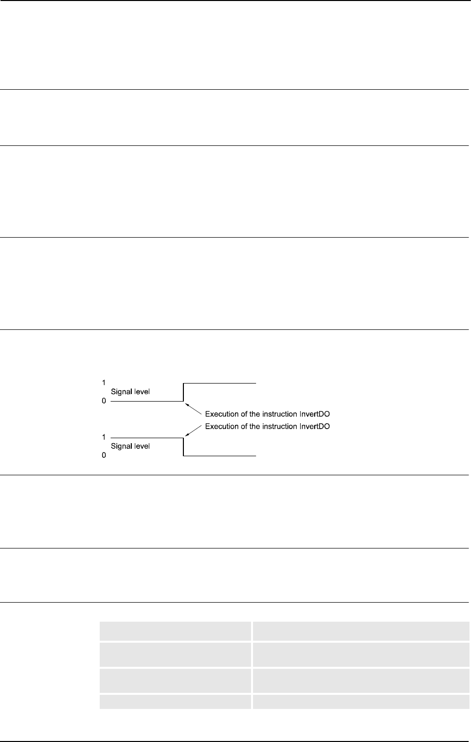
1 Instructions
1.66. InvertDO - Inverts the value of a digital output signal
RobotWare - OS
3HAC 16581-1 Revision: J154
© Copyright 2004-2010 ABB. All rights reserved.
1.66. InvertDO - Inverts the value of a digital output signal
Usage
InvertDO (Invert Digital Output) inverts the value of a digital output signal (0 -> 1 and 1 -
> 0).
Basic examples
Basic examples of the instruction
InvertDO are illustrated below.
Example 1
InvertDO do15;
The current value of the signal do15 is inverted.
Arguments
InvertDO Signal
Signal
Data type: signaldo
The name of the signal to be inverted.
Program execution
The current value of the signal is inverted (see figure below).
The figure below shows inversion of digital output signal.
xx0500002164
Error handling
The following recoverable error can be generated. The error can be handled in an error
handler. If there is no contact with the unit the system variable
ERRNO will be set to:
ERR_NORUNUNIT
Syntax
InvertDO
[ Signal ’:=’ ] < variable (VAR) of signaldo > ’;’
Related information
For information about See
Input/Output instructions Technical reference manual - RAPID overview,
section RAPID summary - Input and output signals
Input/Output functionality in general Technical reference manual - RAPID overview,
section Motion and I/O principles - I/O principles
Configuration of I/O Technical reference manual - System parameters

1 Instructions
1.67. IOBusStart - Start of I/O bus
RobotWare - OS
1553HAC 16581-1 Revision: J
© Copyright 2004-2010 ABB. All rights reserved.
1.67. IOBusStart - Start of I/O bus
Usage
IOBusStart is used to start a certain I/O bus.
Basic examples
Basic example of the instruction
IOBusStart is illustrated below.
Example 1
IOBusStart "IBS";
The instruction start the bus with the name IBS.
Arguments
IOBusStart BusName
BusName
Data type: string
The name of bus to start.
Program execution
Start the bus with the name specified in the parameter
BusName.
Error handling
The system variable
ERRNO will be set to ERR_NAME_INVALID if the bus name does not
exist.That error can be handled in an
ERROR handler.
Syntax
IOBusStart
[ BusName ’:=’ ] < expression (IN) of string>’;’
Related information
For information about See
How to get I/O bus state IOBusState - Get current state of I/O bus on
page 156
Configuration of I/O Technical reference manual - System
parameters

1 Instructions
1.68. IOBusState - Get current state of I/O bus
RobotWare - OS
3HAC 16581-1 Revision: J156
© Copyright 2004-2010 ABB. All rights reserved.
1.68. IOBusState - Get current state of I/O bus
Usage
IOBusState is used to read the state of a certain I/O bus. Its physical state and logical state
define the status for an I/O bus.
Basic examples
Basic examples of the instruction
IOBusState are illustrated below.
Example 1
VAR busstate bstate;
IOBusState "IBS", bstate \Phys;
TEST bstate
CASE IOBUS_PHYS_STATE_RUNNING:
! Possible to access the signals on the IBS bus
DEFAULT:
! Actions for not up and running IBS bus
ENDTEST
The instruction returns the physical bus state of IBS in the bstate variable of type
busstate.
Example 2
VAR busstate bstate;
IOBusState "IBS", bstate \Logic;
TEST bstate
CASE IOBUS_LOG_STATE_STARTED:
! The IBS bus is started
DEFAULT:
! Actions for stopped IBS bus
ENDTEST
The instruction returns the logical bus state of IBS in the bstate variable of type busstate.
Arguments
IOBusState BusName State [\Phys] | [\Logic]
BusName
Data type: string
The name of bus to get state about.
State
Data type: busstate
The variable in which the bus state is returned. See predefined data of type busstate below
at Program execution.
Continues on next page

1 Instructions
1.68. IOBusState - Get current state of I/O bus
RobotWare - OS
1573HAC 16581-1 Revision: J
© Copyright 2004-2010 ABB. All rights reserved.
[\Phys]
Physical
Data type:
switch
If using this parameter the physical state of the bus is read.
[\Logic]
Logical
Data type:
switch
If using this parameter the logical state of the bus is read.
Program execution
Returning in parameter
State the state of the bus is specified in parameter BusName.
The I/O bus logical states describe the state a user can order the bus into. The state of the I/O
bus is defined in the table below when using optional argument
\Logic.
The I/O bus physical state describes the state that the fieldbus driver can order the bus into.
The state of the I/O bus is defined in the table below when using optional argument
\Phys.
-
NOTE!
For RobotWare 5.08 and earlier versions it is not possible to use the instruction
IOBusState
with optional argument
\Phys or \Logic. From RobotWare 5.09 it is recommended to use
the optional argument
\Phys or \Logic.
Return value Symbolic constant Comment
10 IOBUS_LOG_STATE_STOPPED Bus is stopped due to error
2)
11 IOBUS_LOG_STATE_STARTED Bus is started
1)
Return value Symbolic constant Comment
20 IOBUS_PHYS_STATE_HALTED Bus is halted
3)
21 IOBUS_PHYS_STATE_RUNNING Bus is up and running
1)
22 IOBUS_PHYS_STATE_ERROR Bus is not working
2)
23 IOBUS_PHYS_STATE_STARTUP Bus is in start up mode, is not com-
municating with any units.
24 IOBUS_PHYS_STATE_INIT Bus is only created
3)
Continued
Continues on next page

1 Instructions
1.68. IOBusState - Get current state of I/O bus
RobotWare - OS
3HAC 16581-1 Revision: J158
© Copyright 2004-2010 ABB. All rights reserved.
The state of the I/O bus is defined in the table below when not using any of the optional
argument
\Phys or \Logic.
1)
If the bus is up and running the state returned in argument State in instruction
IOBusState can be either IOBUS_LOG_STATE_STARTED, IOBUS_PHYS_STATE_RUNNING,
or
BUSSTATE_RUN depending on if optional parameters are used or not in IOBusState.
2)
If the bus is stopped due to some error the state returned in argument State can be either
IOBUS_LOG_STATE_STOPPED, IOBUS_PHYS_STATE_ERROR, or BUSSTATE_ERROR
depending on if optional parameters are used or not in
IOBusState.
3)
Not possible to get this state in the RAPID program with current version of Robotware - OS.
Error handling
The system variable
ERRNO will be set to ERR_NAME_INVALID if the bus name does not
exist.That error can be handled in an
ERROR handler
Syntax
IOBusState
[ BusName ’:=’ ] < expression (IN) of string> ’,’
[ State ’:=’ ] < variable (VAR) of busstate>
[ ’\’ Phys] | [ ’\’ Logic]’;’
Related information
Return value Symbolic constant Comment
0 BUSSTATE_HALTED Bus is halted
3)
1 BUSSTATE_RUN Bus is up and running
1)
2 BUSSTATE_ERROR Bus is not working
2)
3 BUSSTATE_STARTUP Bus is in start up mode, is not com-
municating with any units.
4 BUSSTATE_INIT Bus is only created
3)
For information about See
Definition of bus state busstate - State of I/O bus on page 1088
Start of I/O bus IOBusStart - Start of I/O bus on page 155
Input/Output functionality in general Technical reference manual - RAPID overview, section
Motion and I/O Principles -I/O principles
Configuration of I/O Technical reference manual - System parameters
Continued

1 Instructions
1.69. IODisable - Disable I/O unit
RobotWare - OS
1593HAC 16581-1 Revision: J
© Copyright 2004-2010 ABB. All rights reserved.
1.69. IODisable - Disable I/O unit
Usage
IODisable is used to deactivate an I/O unit during program execution.
I/O units are automatically activated after start-up if they are defined in the system
parameters. When required for some reason, I/O units can be deactivated or activated during
program execution.
NOTE!
It is not possible to deactivate a unit with Trustlevel set to Required.
Basic examples
Basic examples of the instruction
IODisable are illustrated below.
See also More examples on page 160.
Example 1
CONST string cell1:="cell1";
IODisable cell1, 5;
Deactivate an I/O unit with name cell1. Wait max. 5 s.
Arguments
IODisable UnitName MaxTime
UnitName
Data type: string
A name of an I/O unit (the unit name must be present in the system parameters).
MaxTime
Data type: num
The maximum period of waiting time permitted expressed in seconds. If this time runs out
before the I/O unit has finished the deactivation steps the error handler will be called, if there
is one, with the error code
ERR_IODISABLE. If there is no error handler the program
execution will be stopped. However, the I/O unit deactivationprocess will always continue
regardless of the
MaxTime or error.
To deactivate an I/O unit takes about 0-5 s.
Program execution
The specified I/O unit starts the deactivation steps. The instruction is ready when the
deactivation steps are finished. If the
MaxTime runs out before the I/O unit has finished the
deactivation steps, a recoverable error will be generated.
After deactivation of an I/O unit, any setting of outputs in this unit will result in an error.
Continues on next page

1 Instructions
1.69. IODisable - Disable I/O unit
RobotWare - OS
3HAC 16581-1 Revision: J160
© Copyright 2004-2010 ABB. All rights reserved.
Error handling
The following recoverable errors can be generated. The errors can be handled in an error
handler. The system variable
ERRNO will be set to:
More examples
More examples of the instruction
IODisable are illustrated below.
Example 1
PROC go_home()
VAR num recover_flag :=0;
...
! Start to disable I/O unit cell1
recover_flag := 1;
IODisable "cell1", 0;
! Move to home position
MoveJ home, v1000,fine,tool1;
! Wait until deactivation of I/O unit cell1 is ready
recover_flag := 2;
IODisable "cell1", 5;
...
ERROR
IF ERRNO = ERR_IODISABLE THEN
IF recover_flag = 1 THEN
TRYNEXT;
ELSEIF recover_flag = 2 THEN
RETRY;
ENDIF
ELSEIF ERRNO <> ERR_EXCRTYMAX THEN
RAISE;
ELSE
ErrWrite "IODisable error", "Not possible to disable I/O
unit cell1";
Stop;
ENDIF
ENDPROC
To save cycle time the I/O unit cell1 is deactivated during robot movement to the home
position. With the robot at the
home position a test is done to establish whether or not the I/O
unit
cell1 is fully deactivated. After the max. number of retries (5 with a waiting time of
5 s), the robot execution will stop with an error message.
The same principle can be used with
IOEnable (this will save more cycle time compared
with
IODisable).
ERR_IODISABLE if the time out time runs out before the unit is deactivated.
ERR_TRUSTLEVEL if the trustlevel on the unit is set to 0, then the unit can´t be
deactivated.
ERR_NAME_INVALID if the unit name don’t exist or if the unit isn’t allowed to be
deactivated.
Continued
Continues on next page

1 Instructions
1.69. IODisable - Disable I/O unit
RobotWare - OS
1613HAC 16581-1 Revision: J
© Copyright 2004-2010 ABB. All rights reserved.
Syntax
IODisable
[ UnitName ’:=’ ] < expression (IN) of string> ’,’
[ MaxTime ’:=’ ] < expression (IN) of num> ’;’
Related information
For information about See
Enabling an I/O unit IOEnable - Enable I/O unit on page 162
Input/Output instructions Technical reference manual - RAPID overview,
section RAPID Summary - Input and output
signals
Input/Output functionality in general Technical reference manual - RAPID overview,
section Motion and I/O Principles - I/O Principles
Configuration of I/O Technical reference manual - System parameters
Continued

1 Instructions
1.70. IOEnable - Enable I/O unit
RobotWare - OS
3HAC 16581-1 Revision: J162
© Copyright 2004-2010 ABB. All rights reserved.
1.70. IOEnable - Enable I/O unit
Usage
IOEnable is used to activate an I/O unit during program execution.
I/O units are automatically activated after start-up if they are defined in the system
parameters. When required for some reason I/O units can be deactivated or activated during
program execution.
The controller action when activating a unit depends on the set unit Trustlevel. See System
Parameters Unit Trustlevel.
Basic examples
Basic examples of the instruction
IOEnable are illustrated below.
See also More examples on page 163.
Example 1
CONST string cell1:="cell1";
IOEnable cell1, 5;
Enable I/O unit with name cell1. Wait max. 5 s.
Arguments
IOEnable UnitName MaxTime
UnitName
Data type: string
A name of an I/O unit (the unit name must be present in the system parameters).
MaxTime
Data type: num
The maximum period of waiting time permitted, expressed in seconds. If this time runs out
before the I/O unit has finished the activation steps the error handler will be called, if there is
one, with the error code
ERR_IOENABLE. If there is no error handler the execution will be
stopped. The I/O unit activation process will however always continue regardless of
MaxTime or error.
To activate an I/O unit takes about 2-5 s.
Program execution
The specified I/O unit starts the activation steps. The instruction is ready when the activation
steps are finished. If the
MaxTime runs out before the I/O unit has finished the activation steps
a recoverable error will be generated.
After a sequence of
IODisable - IOEnable, all outputs for the current I/O unit will be set
to the old values (before
IODisable).
Continues on next page

1 Instructions
1.70. IOEnable - Enable I/O unit
RobotWare - OS
1633HAC 16581-1 Revision: J
© Copyright 2004-2010 ABB. All rights reserved.
Error handling
The following recoverable errors can be generated. The errors can be handled in an error
handler. The system variable
ERRNO will be set to:
More examples
IOEnable can also be used to check whether some I/O unit is disconnected for some reason.
More examples of how to use the instruction
IOEnable are illustrated below.
Example 1
VAR num max_retry:=0;
...
IOEnable "cell1", 0;
SetDO cell1_sig3, 1;
...
ERROR
IF ERRNO = ERR_IOENABLE THEN
WaitTime 1;
RETRY;
ELSEIF ERRNO <> Err_EXCRTYMAX THEN
RAISE;
ELSE
ErrWrite "IOEnable error", "Not possible to enable I/O
unit cell";
Stop;
ENDIF
ENDIF
Before using signals on the I/O unit cell1, a test is done by trying to activate the I/O unit
with timeout after
0 sec. If the test fails a jump is made to the error handler. In the error
handler the program execution waits for
1 sec. and a new retry is made. After 5 retry attempts
the error
ERR_IOENABLE is propagated to the caller of this routine.
Syntax
IOEnable
[ UnitName ’:=’ ] < expression (IN) of string>’ ,’
[ MaxTime’ :=’ ] < expression (IN) of num > ’;’
ERR_IOENABLE if the time out time runs out before the unit is activated.
ERR_NAME_INVALID if the unit name don’t exist or if the unit isn’t allowed to be
activated.
ERR_BUSSTATE if an IOEnable is done, and the bus is in error state or
enter error state before the unit is activated.
Continued
Continues on next page

1 Instructions
1.70. IOEnable - Enable I/O unit
RobotWare - OS
3HAC 16581-1 Revision: J164
© Copyright 2004-2010 ABB. All rights reserved.
Related information
For information about See
Disabling an I/O unit IODisable - Disable I/O unit on page 159
Input/Output instructions Technical reference manual - RAPID overview,
section RAPID Summary - Input and Output Signals
Input/Output functionality in general Technical reference manual - RAPID overview,
section Motion and I/O Principles - I/O principles
Configuration of I/O Technical reference manual - System parameters
Continued

1 Instructions
1.71. IPers - Interrupt at value change of a persistent variable
RobotWare - OS
1653HAC 16581-1 Revision: J
© Copyright 2004-2010 ABB. All rights reserved.
1.71. IPers - Interrupt at value change of a persistent variable
Usage
IPers (Interrupt Persistent) is used to order and enable interrupts to be generated when the
value of a persistent variable is changed.
Basic examples
Basic examples of the instruction
IPers are illustrated below.
Example 1
VAR intnum pers1int;
PERS num counter := 0;
PROC main()
CONNECT pers1int WITH iroutine1;
IPers counter, pers1int;
...
Idelete pers1int;
ENDPROC
TRAP iroutine1
TPWrite "Current value of counter = " \Num:=counter;
ENDTRAP
Orders an interrupt which is to occur each time the persistent variable counter is changed.
A call is then made to the
iroutine1 trap routine.
Arguments
IPers Name Interrupt
Name
Data type: anytype
The persistent variable that is to generate interrupts.
All type of data could be used such as atomic, record, record component, array, or array
element.
Interrupt
Data type: intnum
The interrupt identity. This should have previously been connected to a trap routine by means
of the instruction
CONNECT.
Program execution
When the persistent variable changes value a call is made to the corresponding trap routine.
When this routine has been executed program execution continues from where the interrupt
occurred.
If the persistent variable changes value during a program stop no interrupt will occur when
the program starts again.
Continues on next page

1 Instructions
1.71. IPers - Interrupt at value change of a persistent variable
RobotWare - OS
3HAC 16581-1 Revision: J166
© Copyright 2004-2010 ABB. All rights reserved.
Limitations
The same variable for interrupt identity cannot be used more than once without first deleting
it. See Instructions -
ISignalDI.
If subscribed on data such as record component or array element specified in parameter
Name,
the interrupt will occur every time any part of the data is changed.
When executing the trap routine and reading the value of the persistent, there is no guarantee
that the value read is the one that triggered the interrupt.
Syntax
IPers
[ Name ’:=’ ] < persistent (PERS) of anytype > ’,’
[ Interrupt’ :=’ ] < variable (VAR) of intnum > ’;’
Related information
For information about See
Summary of interrupts Technical reference manual - RAPID
overview, section RAPID summary -
Interrupts
Interrupt from an input signal ISignalDI - Orders interrupts from a digital
input signal on page 186
More information about interrupt
management
Technical reference manual - RAPID
overview, section Basic characteristics -
Interrupts
Interrupt identity intnum - Interrupt identity on page 1125
Continued

1 Instructions
1.72. IRMQMessage - Orders RMQ interrupts for a data type
FlexPendant Interface, PC Interface, or Multitasking
1673HAC 16581-1 Revision: J
© Copyright 2004-2010 ABB. All rights reserved.
1.72. IRMQMessage - Orders RMQ interrupts for a data type
Usage
IRMQMessage (Interrupt RAPID Message Queue Message) is used to order and enable
interrupts for a specific data type when using RMQ functionality.
Basic examples
Basic examples of the instruction
IRMQMessage are illustrated below.
See also More Examples.
Example 1
VAR intnum rmqint;
VAR string dummy;
...
CONNECT rmqint WITH iroutine1;
IRMQMessage dummy, rmqint;
Orders an interrupt which is to occur each time a new rmqmessage containing the data type
string is received. A call is then made to the iroutine1 TRAP routine.
Arguments
IRMQMessage InterruptDataType Interrupt
InterruptDataType
Data type: anytype
A reference to a variable, persistent or constant of a data type that will generate an interrupt
when a
rmqmessage with the specified data type is received.
Interrupt
Data type: intnum
The interrupt identity. This should have previously been connected to a TRAP routine by
means of the instruction
CONNECT.
Continues on next page

1 Instructions
1.72. IRMQMessage - Orders RMQ interrupts for a data type
FlexPendant Interface, PC Interface, or Multitasking
3HAC 16581-1 Revision: J168
© Copyright 2004-2010 ABB. All rights reserved.
Program execution
When the RMQ message with the specified data type is received, a call is made to the
corresponding TRAP routine. When this has been executed, program execution continues
from where the interrupt occurred.
All messages containing data of the same data type regardless of number of dimensions will
be handled by the same interrupt. If using different dimensions, use
RMQGetMsgHeader to
adapt for this.
Any message containing data of a data type that no interrupt is connected to will genererate
a warning.
The
RMQSendWait instruction has the highest priority if a message is received and it fits the
description for both the expected answer and a message connected to a TRAP routine with
instruction
IRMQMessage.
Not all data types can be used in argument
InterruptDataType (see limitations).
The interrupt is considered to be a safe interrupt. A safe interrupt can not be put in sleep with
instruction
ISleep. The safe interrupt event will be queued at program stop and stepwise
execution, and when starting in continious mode again, the interrupt will be executed. The
only time a safe interrupt will be thrown is when the interrupt queue is full. Then an error will
be reported. The interrupt will not survive program reset, e.g. PP to main.
More examples
More examples of how to use the instruction
IRMQMessage are illustrated below.
Example 1
MODULE ReceiverMod
VAR intnum intno1;
VAR rmqheader rmqheader1;
VAR rmqslot rmqslot1;
VAR rmqmessage rmqmessage1;
PROC main()
VAR string interrupt_on_str := stEmpty;
CONNECT intno1 WITH RecMsgs;
! Set up interrupts for data type string
IRMQMessage interrupt_on_str, intno1;
! Perform cycle
WHILE TRUE DO
...
ENDWHILE
ENDPROC
Continued
Continues on next page

1 Instructions
1.72. IRMQMessage - Orders RMQ interrupts for a data type
FlexPendant Interface, PC Interface, or Multitasking
1693HAC 16581-1 Revision: J
© Copyright 2004-2010 ABB. All rights reserved.
TRAP RecMsgs
VAR string receivestr;
VAR string client_name;
VAR num userdef;
! Get the message from the RMQ
RMQGetMessage rmqmessage1;
! Get information about the message
RMQGetMsgHeader rmqmessage1 \Header:=rmqheader1
\SenderId:=rmqslot1 \UserDef:=userdef;
IF rmqheader1.datatype = "string" AND rmqheader1.ndim = 0 THEN
! Get the data received in rmqmessage1
RMQGetMsgData rmqmessage1, receivestr;
client_name := RMQGetSlotName(rmqslot1);
TPWrite "Rec string: " + receivestr;
TPWrite "User Def: " + ValToStr(userdef);
TPWrite "From: " + client_name;
ELSE
TPWrite "Faulty data received!"
ENDIF
ENDTRAP
ENDMODULE
The example show how to set up interrupts for a specific data type. When a message is
received, the
TRAP RecMsgs is executed and the received data in the message is printed to
the FlexPendant. If the data type received or the dimension of the data is different from the
expected, this is printed to the FlexPendant.
Limitations
It is not allowed to execute
IRMQMessage in synchronous mode. That will cause a fatal
runtime error.
It is not possible to setup interrupts, send or receive data instances of data types that are of
non-value, semi-value types or data type
motsetdata.
The same variable for interrupt identity can not be used more than once without first deleting
it. Interrupts should therefore be handled as shown in one of the alternatives below.
PROC main ()
VAR intnum rmqint;
VAR mytype dummy;
CONNECT rmq1int WITH iroutine1;
IRMQMessage dummy, rmqint;
WHILE TRUE DO
...
ENDWHILE
ENDPROC
Continued
Continues on next page

1 Instructions
1.72. IRMQMessage - Orders RMQ interrupts for a data type
FlexPendant Interface, PC Interface, or Multitasking
3HAC 16581-1 Revision: J170
© Copyright 2004-2010 ABB. All rights reserved.
All activation of interrupts is done at the beginning of the program. These beginning
instructions are then kept outside the main flow of the program.
PROC main ( )
VAR intnum rmqint;
VAR mytype dummy;
CONNECT rmqint WITH iroutine1;
IRMQMessage dummy, rmqint;
...
IDelete rmqint;
ENDPROC
The interrupt is deleted at the end of the program, and is then reactivated. It should be noted,
in this case, that the interrupt is inactive for a short period.
Syntax
IRMQMessage
[ InterruptDataType‘ :=’ ] < reference (REF) of anytype >
[ Interrupt‘ :=’ ] < variable (VAR) of intnum >‘;‘
Related information
For information about See
Description of the RAPID Message Queue
functionality
Application manual - Robot communication
and I/O control, section RAPID Message
Queue.
Send data to the queue of a RAPID task or
Robot Application Builder client.
RMQFindSlot - Find a slot identity from the
slot name on page 371
Get the first message from a RAPID Message
Queue.
RMQGetMessage - Get an RMQ message on
page 373
Send data to the queue of a RAPID task or
Robot Application Builder client, and wait for
an answer from the client.
RMQSendWait - Send an RMQ data
message and wait for a response on page
390
Extract the header data from a rmqmessage. RMQGetMsgHeader - Get header
information from an RMQ message on page
380
Send data to the queue of a RAPID task or
Robot Application Builder client.
RMQSendMessage - Send an RMQ data
message on page 386
Extract the data from a rmqmessage. RMQGetMsgData - Get the data part from an
RMQ message on page 377
Get the slot name from a specified slot
identity.
RMQGetSlotName - Get the name of an
RMQ client on page 964
Continued

1 Instructions
1.73. ISignalAI - Interrupts from analog input signal
RobotWare - OS
1713HAC 16581-1 Revision: J
© Copyright 2004-2010 ABB. All rights reserved.
1.73. ISignalAI - Interrupts from analog input signal
Usage
ISignalAI (Interrupt Signal Analog Input) is used to order and enable interrupts from an
analog input signal.
Basic examples
Basic examples of the instruction
ISignalAI are illustrated below.
Example 1
VAR intnum sig1int;
CONNECT sig1int WITH iroutine1;
ISignalAI \Single, ai1, AIO_BETWEEN, 1.5, 0.5, 0, sig1int;
Orders an interrupt which is to occur the first time the logical value of the analog input signal
ai1 is between 0.5 and 1.5. A call is then made to the iroutine1 trap routine.
Example 2
ISignalAI ai1, AIO_BETWEEN, 1.5, 0.5, 0.1, sig1int;
Orders an interrupt which is to occur each time the logical value of the analog input signal
ai1 is between 0.5 and 1.5, and the absolute signal difference compared to the stored
reference value is bigger than
0.1.
Example 3
ISignalAI ai1, AIO_OUTSIDE, 1.5, 0.5, 0.1, sig1int;
Orders an interrupt which is to occur each time the logical value of the analog input signal
ai1 is lower than 0.5 or higher than 1.5, and the absolute signal difference compared to the
stored reference value is bigger than
0.1.
Arguments
ISignalAI [\Single] | [\SingleSafe] Signal Condition HighValue
LowValue DeltaValue [\DPos] | [\DNeg] Interrupt
[\Single]
Data type: switch
Specifies whether the interrupt is to occur once or cyclically. If the argument Single is set,
the interrupt occurs once at the most. If the
Single and SingleSafe arguments is omitted,
an interrupt will occur each time its condition is satisfied.
[\SingleSafe]
Data type: switch
Specifies that the interrupt is single and safe. For definition of single, see description of
Single argument. A safe interrupt can not be put in sleep with instruction ISleep. The safe
interrupt event will be queued at program stop and stepwise execution, and when starting in
continious mode again, the interrupt will be executed. The only time a safe interrupt will be
thrown is when the interrupt queue is full. Then an error will be reported. The interrupt will
not survive program reset, e.g. PP to main.
Continues on next page

1 Instructions
1.73. ISignalAI - Interrupts from analog input signal
RobotWare - OS
3HAC 16581-1 Revision: J172
© Copyright 2004-2010 ABB. All rights reserved.
Signal
Data type: signalai
The name of the signal that is to generate interrupts.
Condition
Data type: aiotrigg
Specifies how HighValue and LowValue define the condition to be satisfied:
HighValue
Data type: num
High logical value to define the condition.
LowValue
Data type: num
Low logical value to define the condition.
DeltaValue
Data type: num
Defines the minimum logical signal difference before generation of a new interrupt. The
current signal value compared to the stored reference value must be greater than the specified
DeltaValue before generation of a new interrupt.
[\DPos]
Data type: switch
Specifies that only positive logical signal differences will give new interrupts.
[\DNeg]
Data type: switch
Specifies that only negative logical signal differences will give new interrupts.
If none of
\DPos and \DNeg argument is used, both positive and negative differences will
generate new interrupts.
Interrupt
Data type: intnum
The interrupt identity. This interrupt should have previously been connected to a trap routine
by means of the instruction
CONNECT.
Value Symbolic constant Comment
1 AIO_ABOVE_HIGH Signal will generate interrupts if above specified high value
2 AIO_BELOW_HIGH Signal will generate interrupts if below specified high value
3 AIO_ABOVE_LOW Signal will generate interrupts if above specified low value
4 AIO_BELOW_LOW Signal will generate interrupts if below specified low value
5 AIO_BETWEEN Signal will generate interrupts if between specified low and
high values
6 AIO_OUTSIDE Signal will generate interrupts if below specified low value
or above specified high value
7 AIO_ALWAYS Signal will always generate interrupts
Continued
Continues on next page

1 Instructions
1.73. ISignalAI - Interrupts from analog input signal
RobotWare - OS
1733HAC 16581-1 Revision: J
© Copyright 2004-2010 ABB. All rights reserved.
Program execution
When the signal fulfils the specified conditions (both
Condition and DeltaValue) a call
is made to the corresponding trap routine. When this has been executed, program execution
continues from where the interrupt occurred.
Conditions for interrupt generation
Before the interrupt subscription is ordered, each time the signal is sampled, the value of the
signal is read, saved, and later used as a reference value for the
DeltaValue condition.
At the interrupt subscription time if specified
DeltaValue = 0 and after the interrupt
subscription time, the signal is sampled. The signal value is then compared to
HighValue
and
LowValue according to Condition and with consideration to DeltaValue to decide if
an interrupt should be generated or not. If the new read value satisfies the specified
HighValue and LowValue Condition, but its difference compared to the last stored
reference value is less or equal to the
DeltaValue argument, no interrupt occurs. If the signal
difference is not in the specified direction no interrupts will occur (argument
\DPos or
\DNeg).
The stored reference value for the
DeltaValue condition is updated with a newly read value
for later use at any sample if the following conditions are satisfied:
• Argument Condition with specified HighValue and LowValue (within limits)
• Argument DeltaValue (sufficient signal change in any direction independently of
specified switch
\DPos or \DNeg)
The reference value is only updated at the sample time, not at the interrupt subscription time.
An interrupt is also generated at the sample for update of the reference value if the direction
of the signal difference is in accordance with the specified argument (any direction,
\DPos0,
or
\DNeg).
When the
\Single switch is used only one interrupt at the most will be generated. If the
switch
\Single (cyclic interrupt) is not used a new test of the specified conditions (both
Condition and DeltaValue) is made at every sample of the signal value. Acomparison is
made between the current signal value and the last stored reference value to decide if an
interrupt should be generated or not.
Continued
Continues on next page
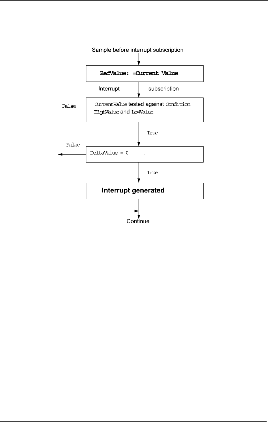
1 Instructions
1.73. ISignalAI - Interrupts from analog input signal
RobotWare - OS
3HAC 16581-1 Revision: J174
© Copyright 2004-2010 ABB. All rights reserved.
Condition for interrupt generation at interrupt subscription time
xx0500002165
Continued
Continues on next page
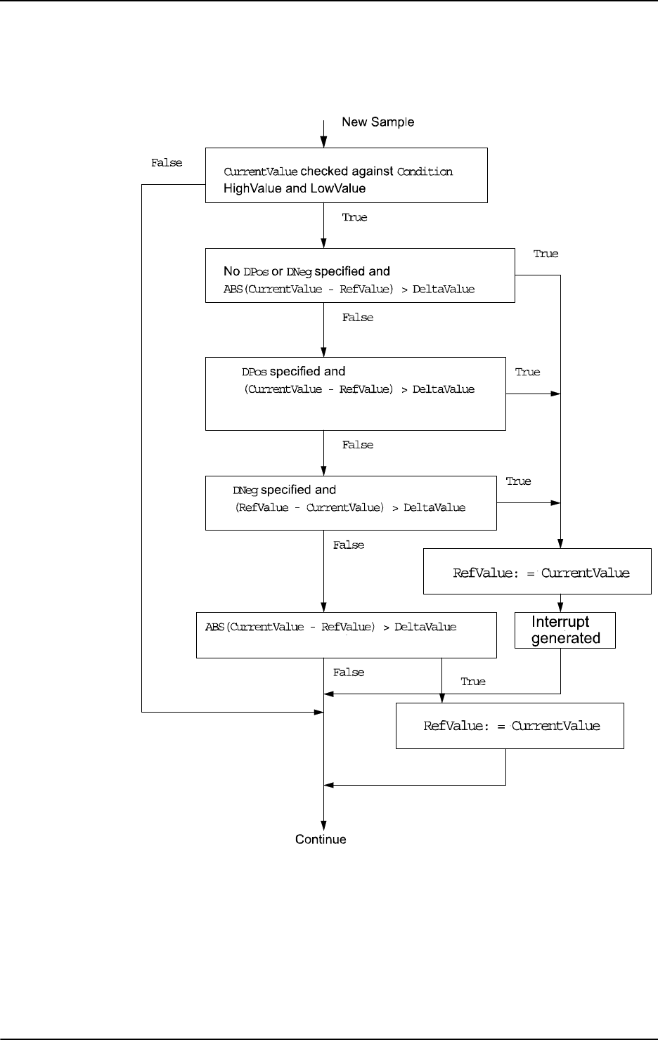
1 Instructions
1.73. ISignalAI - Interrupts from analog input signal
RobotWare - OS
1753HAC 16581-1 Revision: J
© Copyright 2004-2010 ABB. All rights reserved.
Condition for interrupt generation at each sample after interrupt subscription
xx0500002166
Continued
Continues on next page

1 Instructions
1.73. ISignalAI - Interrupts from analog input signal
RobotWare - OS
3HAC 16581-1 Revision: J176
© Copyright 2004-2010 ABB. All rights reserved.
Example 1 of interrupt generation
xx0500002167
Assuming the interrupt is ordered between sample 0 and 1, the following instruction will give
the following results:
ISignalAI ai1, AIO_BETWEEN, 6.1, 2.2, 1.0, sig1int;
Sample 1 will generate an interrupt because the signal value is between HighValue and
LowValue and the signal difference compared to Sample 0 is more than DeltaValue.
Sample 2 will generate an interrupt because the signal value is between
HighValue and
LowValue and the signal difference compared to Sample 1 is more than DeltaValue.
Samples 3, 4, 5 will not generate any interrupt because the signal difference is less than
DeltaValue.
Sample 6 will generate an interrupt.
Samples 7 to 10 will not generate any interrupt because the signal is above
HighValue.
Sample 11 will not generate any interrupt because the signal difference compared to Sample
6 is equal to
DeltaValue.
Sample 12 will not generate any interrupt because the signal difference compared to Sample
6 is less than
DeltaValue.
Continued
Continues on next page

1 Instructions
1.73. ISignalAI - Interrupts from analog input signal
RobotWare - OS
1773HAC 16581-1 Revision: J
© Copyright 2004-2010 ABB. All rights reserved.
Example 2 of interrupt generation
xx0500002168
Assuming the interrupt is ordered between sample 0 and 1, the following instruction will give
the following results:
ISignalAI ai1, AIO_BETWEEN, 6.1, 2.2, 1.0 \DPos, sig1int;
A new reference value is stored at sample 1 and 2 because the signal is within limits and the
absolute signal difference between the current value and the last stored reference value is
greater than 1.0. No interrupt will be generated because the signal changes are in the negative
direction.
Sample 6 will generate an interrupt because the signal value is between
HighValue and
LowValue, and the signal difference in the positive direction compared to sample 2 is more
than
DeltaValue.
Continued
Continues on next page
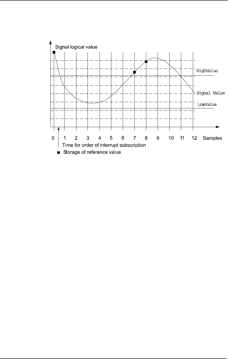
1 Instructions
1.73. ISignalAI - Interrupts from analog input signal
RobotWare - OS
3HAC 16581-1 Revision: J178
© Copyright 2004-2010 ABB. All rights reserved.
Example 3 of interrupt generation
xx0500002169
Assuming the interrupt is ordered between sample 0 and 1, the following instruction will give
the following results:
ISignalAI \Single, ai1, AIO_OUTSIDE, 6.1, 2.2, 1.0 \DPos, sig1int;
A new reference value is stored at sample 7 because the signal is within limits and the
absolute signal difference between the current value and the last stored reference value is
greater than 1.0
sample 8 will generate an interrupt because the signal value is above
HighValue, and the
signal difference in the positive direction compared to sample 7 is more than
DeltaValue.
Continued
Continues on next page
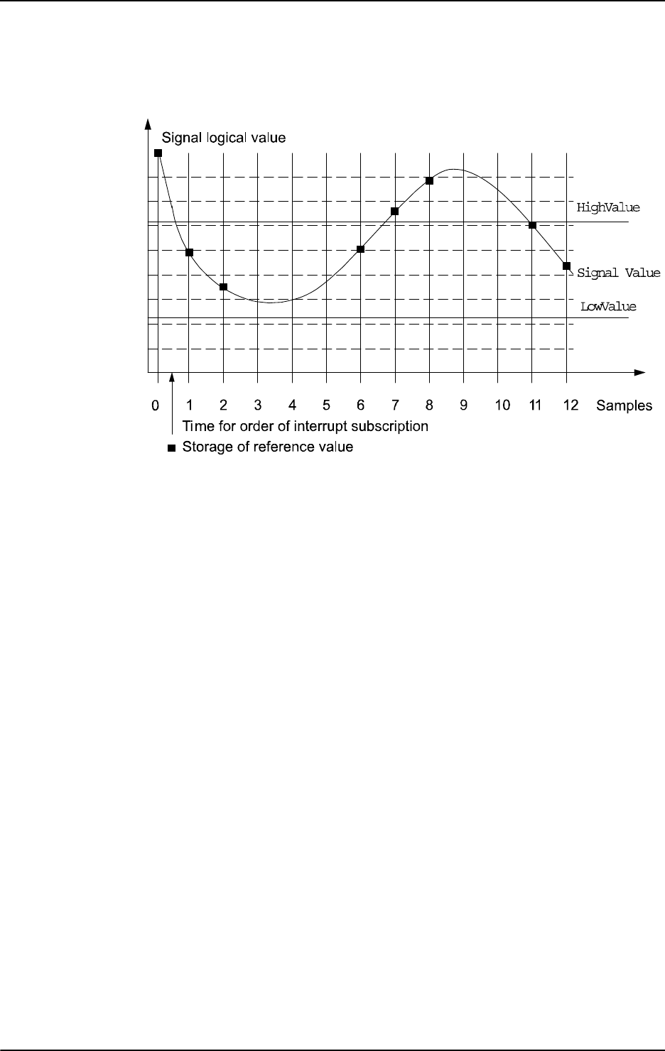
1 Instructions
1.73. ISignalAI - Interrupts from analog input signal
RobotWare - OS
1793HAC 16581-1 Revision: J
© Copyright 2004-2010 ABB. All rights reserved.
Example 4 of interrupt generation
xx0500002170
Assuming the interrupt is ordered between sample 0 and 1, the following instruction will give
the following results:
ISignalAI ai1, AIO_ALWAYS, 6.1, 2.2, 1.0 \DPos, sig1int;
A new reference value is stored at sample 1 and 2 because the signal is within limits and the
absolute signal difference between the current value and the last stored reference value is
greater than 1.0
Sample 6 will generate an interrupt because the signal difference in the positive direction
compared to sample 2 is more than
DeltaValue.
Sample 7 and 8 will generate an interrupt because the signal difference in the positive
direction compared to previous sample is more than
DeltaValue.
A new reference value is stored at sample 11 and 12 because the signal is within limits, and
the absolute signal difference between the current value and the last stored reference value is
greater than 1.0
Continued
Continues on next page

1 Instructions
1.73. ISignalAI - Interrupts from analog input signal
RobotWare - OS
3HAC 16581-1 Revision: J180
© Copyright 2004-2010 ABB. All rights reserved.
Error handling
If there is a subscription of interrupt on an analog input signal, an interrupt will be given for
every change in the analog value that satisfies the condition specified when ordering the
interrupt subscription. If the analog value is noisy many interrupts can be generated even if
only one or two bits in the analog value are changed.
To avoid generating interrupts for small changes of the analog input value, set the
DeltaValue to a level greater than 0. Then no interrupts will be generated until a change of
the analog value is greater than the specified
DeltaValue.
Following recoverable error can be generated. The error can be handled in an error handler.
The system variable
ERRNO will be set to:
ERR_NORUNUNIT
if there is no contact with the unit.
ERR_AO_LIM
if the programmed HighValue or LowValue argument for the specified analog input signal
Signal is outside limits.
Limitations
The
HighValue and LowValue arguments should be in the range: logical maximum value,
logical minimum value defined for the signal.
HighValue must be above LowValue.
DeltaValue must be 0 or positive.
The limitations for the interrupt identity are the same as for
ISignalDI.
Syntax
ISignalAI
[ ’\’ Single ] | [ ’\’ SingleSafe ] ’,’
[ Signal’:=’ ]<variable (VAR) of signalai>’,’
[ Condition’:=’ ]<expression (IN) of aiotrigg>’,’
[ HighValue’:=’ ]<expression (IN) of num>’,’
[ LowValue’:=’ ]<expression (IN) of num>’,’
[ DeltaValue’:=’ ]<expression (IN) of num>
[[’\’DPos] | [ ’\’DNeg] ’,’]
[ Interrupt’:=’ ]<variable (VAR) of intnum>’;’
Continued
Continues on next page

1 Instructions
1.73. ISignalAI - Interrupts from analog input signal
RobotWare - OS
1813HAC 16581-1 Revision: J
© Copyright 2004-2010 ABB. All rights reserved.
Related information
For information about See
Summary of interrupts Technical reference manual - RAPID overview,
section RAPID summary - Interrupts
Definition of constants aiotrigg - Analog I/O trigger condition on page
1083
Interrupt from analog output signal ISignalAO - Interrupts from analog output
signal on page 182
Interrupt from digital input signal ISignalDI - Orders interrupts from a digital input
signal on page 186
Interrupt from digital output signal ISignalDO - Interrupts from a digital output
signal on page 189
More information on interrupt management Technical reference manual - RAPID overview,
section Basic Characteristics - Interrupts
Interrupt identity intnum - Interrupt identity on page 1125
Related system parameters (filter) Technical reference manual - System
parameters, section IO signals
Continued

1 Instructions
1.74. ISignalAO - Interrupts from analog output signal
RobotWare - OS
3HAC 16581-1 Revision: J182
© Copyright 2004-2010 ABB. All rights reserved.
1.74. ISignalAO - Interrupts from analog output signal
Usage
ISignalAO (Interrupt Signal Analog Output) is used to order and enable interrupts from an
analog output signal.
Basic examples
Basic examples of the instruction
ISignalAO are illustrated below.
Example 1
VAR intnum sig1int;
CONNECT sig1int WITH iroutine1;
ISignalAO \Single, ao1, AIO_BETWEEN, 1.5, 0.5, 0, sig1int;
Orders an interrupt which is to occur the first time the logical value of the analog output signal
ao1 is between 0.5 and 1.5. A call is then made to the iroutine1 trap routine.
Example 2
ISignalAO ao1, AIO_BETWEEN, 1.5, 0.5, 0.1, sig1int;
Orders an interrupt which is to occur each time the logical value of the analog output signal
ao1 is between 0.5 and 1.5, and the absolute signal difference compared to the previous
stored reference value is bigger than 0.1.
Example 3
ISignalAO ao1, AIO_OUTSIDE, 1.5, 0.5, 0.1, sig1int;
Orders an interrupt which is to occur each time the logical value of the analog output signal
ao1 is lower than 0.5 or higher than 1.5, and the absolute signal difference compared to the
previous stored reference value is bigger than 0.1.
Arguments
ISignalAO [\Single] | [\SingleSafe] Signal Condition HighValue
LowValue DeltaValue [\DPos] | [\DNeg] Interrupt
[\Single]
Data type: switch
Specifies whether the interrupt is to occur once or cyclically. If the argument Single is set
the interrupt occurs once at the most. If the
Single and SingleSafe argument is omitted an
interrupt will occur each time its condition is satisfied.
[\SingleSafe]
Data type: switch
Specifies that the interrupt is single and safe. For definition of single, see description of
Single argument. A safe interrupt can not be put in sleep with instruction ISleep. The safe
interrupt event will be queued at program stop and stepwise execution, and when starting in
continious mode again, the interrupt will be executed. The only time a safe interrupt will be
thrown is when the interrupt queue is full. Then an error will be reported. The interrupt will
not survive program reset, e.g. PP to main.
Continues on next page

1 Instructions
1.74. ISignalAO - Interrupts from analog output signal
RobotWare - OS
1833HAC 16581-1 Revision: J
© Copyright 2004-2010 ABB. All rights reserved.
Signal
Data type: signalao
The name of the signal that is to generate interrupts.
Condition
Data type: aiotrigg
Specifies how HighValue and LowValue define the condition to be satisfied:
HighValue
Data type: num
High logical value to define the condition.
LowValue
Data type: num
Low logical value to define the condition.
DeltaValue
Data type: num
Defines the minimum logical signal difference before generation of a new interrupt. The
current signal value compared to the previous stored reference value must be greater than the
specified
DeltaValue before generation of a new interrupt.
[\DPos]
Data type: switch
Specifies that only positive logical signal differences will give new interrupts.
[\DNeg]
Data type: switch
Specifies that only negative logical signal differences will give new interrupts.
If neither of the
\DPos and \DNeg arguments are used, both positive and negative differences
will generate new interrupts.
Interrupt
Data type: intnum
The interrupt identity. This interrupt should have previously been connected to a trap routine
by means of the instruction
CONNECT.
Value Symbolic constant Comment
1 AIO_ABOVE_HIGH Signal will generate interrupts if above specified high value
2 AIO_BELOW_HIGH Signal will generate interrupts if below specified high value
3 AIO_ABOVE_LOW Signal will generate interrupts if above specified low value
4 AIO_BELOW_LOW Signal will generate interrupts if below specified low value
5 AIO_BETWEEN Signal will generate interrupts if between specified low and
high values
6 AIO_OUTSIDE Signal will generate interrupts if below specified low value
or above specified high value
7 AIO_ALWAYS Signal will always generate interrupts
Continued
Continues on next page

1 Instructions
1.74. ISignalAO - Interrupts from analog output signal
RobotWare - OS
3HAC 16581-1 Revision: J184
© Copyright 2004-2010 ABB. All rights reserved.
Program execution
See instruction
ISignalAI for information about:
• Program execution
• Condition for interrupt generation
• More examples
Same principles are valid for
ISignalAO as for ISignalAI.
Error handling
Following recoverable error can be generated. The error can be handled in an error handler.
The system variable
ERRNO will be set to:
ERR_NORUNUNIT
if there is no contact with the unit.
ERR_AO_LIM
if the programmed HighValue or LowValue argument for the specified analog output signal
Signal is outside limits.
Limitations
The
HighValue and LowValue arguments should be in the range: logical maximum value,
logical minimum value, defined for the signal.
HighValue must be above LowValue.
DeltaValue must be 0 or positive.
The limitations for the interrupt identity are the same as for
ISignalDO.
Syntax
ISignalAO
[ ’\’ Single ] | [ ’\’ SingleSafe ] ’,’
[ Signal’:=’ ]<variable (VAR) of signalao>’,’
[ Condition’:=’ ]<expression (IN) of aiotrigg>’,’
[ HighValue’:=’ ]<expression (IN) of num>’,’
[ LowValue’:=’ ]<expression (IN) of num>’,’
[ DeltaValue’:=’ ]<expression (IN) of num>
[’\’DPos] | [ ’\’DNeg] ’,’]
[ Interrupt’:=’ ]<variable (VAR) of intnum>’;’
Continued
Continues on next page

1 Instructions
1.74. ISignalAO - Interrupts from analog output signal
RobotWare - OS
1853HAC 16581-1 Revision: J
© Copyright 2004-2010 ABB. All rights reserved.
Related information
For information about See
Summary of interrupts Technical reference manual - RAPID
overview, section RAPID Summary -
Interrupts
Definition of constants aiotrigg - Analog I/O trigger condition on page
1083
Interrupt from analog input signal ISignalAI - Interrupts from analog input signal
on page 171
Interrupt from digital input signal ISignalDI - Orders interrupts from a digital
input signal on page 186
Interrupt from digital output signal ISignalDO - Interrupts from a digital output
signal on page 189
More information on interrupt management RAPID reference manual - RAPID overview,
section Basic Characteristics - Interrupts
Interrupt identity intnum - Interrupt identity on page 1125
Related system parameters (filter) Technical reference manual - System
parameters, section IO signals
Continued

1 Instructions
1.75. ISignalDI - Orders interrupts from a digital input signal
RobotWare - OS
3HAC 16581-1 Revision: J186
© Copyright 2004-2010 ABB. All rights reserved.
1.75. ISignalDI - Orders interrupts from a digital input signal
Usage
ISignalDI (Interrupt Signal Digital In) is used to order and enable interrupts from a digital
input signal.
Basic examples
Basic examples of the instruction
ISignalDI are illustrated below.
Example 1
VAR intnum sig1int;
CONNECT sig1int WITH iroutine1;
ISignalDI di1,1,sig1int;
Orders an interrupt which is to occur each time the digital input signal di1 is set to 1. A call
is then made to the
iroutine1 trap routine.
Example 2
ISignalDI di1,0,sig1int;
Orders an interrupt which is to occur each time the digital input signal di1 is set to 0.
Example 3
ISignalDI \Single, di1,1,sig1int;
Orders an interrupt which is to occur only the first time the digital input signal di1 is set to 1.
Arguments
ISignalDI [ \Single] | [ \SingleSafe] Signal TriggValue Interrupt
[ \Single ]
Data type: switch
Specifies whether the interrupt is to occur once or cyclically.
If the argument
Single is set, the interrupt occurs once at the most. If the Single and
SingleSafe arguments is omitted, an interrupt will occur each time its condition is satisfied.
[ \SingleSafe ]
Data type: switch
Specifies that the interrupt is single and safe. For definition of single, see description of
Single argument. A safe interrupt can not be put in sleep with instruction ISleep. The safe
interrupt event will be queued at program stop and stepwise execution, and when starting in
continious mode again, the interrupt will be executed. The only time a safe interrupt will be
thrown is when the interrupt queue is full. Then an error will be reported. The interrupt will
not survive program reset, e.g. PP to main.
Signal
Data type: signaldi
The name of the signal that is to generate interrupts.
Continues on next page

1 Instructions
1.75. ISignalDI - Orders interrupts from a digital input signal
RobotWare - OS
1873HAC 16581-1 Revision: J
© Copyright 2004-2010 ABB. All rights reserved.
TriggValue
Data type: dionum
The value to which the signal must change for an interrupt to occur.
The value is specified as 0 or 1 or as a symbolic value (e.g.
high/low). The signal is edge-
triggered upon changeover to 0 or 1.
TriggValue 2 or symbolic value edge can be used for generation of interrupts on both
positive flank (0 -> 1) and negative flank (1 -> 0).
Interrupt
Data type: intnum
The interrupt identity. This should have previously been connected to a trap routine by means
of the instruction
CONNECT.
Program execution
When the signal assumes the specified value a call is made to the corresponding trap routine.
When this has been executed, program execution continues from where the interrupt
occurred.
If the signal changes to the specified value before the interrupt is ordered no interrupt occurs.
Interrupts from a digital input signal at signal level 1 is illustrated in the figure below.
xx0500002189
Error handling
Following recoverable error can be generated. The error can be handled in an error handler.
The system variable
ERRNO will be set to:
ERR_NORUNUNIT
if there is no contact with the unit.
Continued
Continues on next page

1 Instructions
1.75. ISignalDI - Orders interrupts from a digital input signal
RobotWare - OS
3HAC 16581-1 Revision: J188
© Copyright 2004-2010 ABB. All rights reserved.
Limitations
The same variable for interrupt identity cannot be used more than once without first deleting
it. Interrupts should therefore be handled as shown in one of the alternatives below.
PROC main ( )
VAR intnum sig1int;
CONNECT sig1int WITH iroutine1;
ISignalDI di1, 1, sig1int;
WHILE TRUE DO
...
ENDWHILE
ENDPROC
All activation of interrupts is done at the beginning of the program. These beginning
instructions are then kept outside the main flow of the program.
PROC main ( )
VAR intnum sig1int;
CONNECT sig1int WITH iroutine1;
ISignalDI di1, 1, sig1int;
...
IDelete sig1int;
ENDPROC
The interrupt is deleted at the end of the program and is then reactivated. It should be noted,
in this case, that the interrupt is inactive for a short period.
Syntax
ISignalDI
[ ’\’ Single ] | [ ’\’ SingleSafe ] ’,’
[ Signal ’:=’ ] < variable (VAR) of signaldi > ’,’
[ TriggValue’ :=’ ] < expression (IN) of dionum > ’,’
[ Interrupt’ :=’ ] < variable (VAR) of intnum > ’;’
Related information
For information about See
Summary of interrupts Technical reference manual - RAPID overview,
section RAPID Summary - Interrupts
Interrupt from an output signal ISignalDO - Interrupts from a digital output signal on
page 189
More information on interrupt
management
Technical reference manual - RAPID overview,
section Basic Characteristics - Interrupts
Interrupt identity intnum - Interrupt identity on page 1125
Continued

1 Instructions
1.76. ISignalDO - Interrupts from a digital output signal
RobotWare - OS
1893HAC 16581-1 Revision: J
© Copyright 2004-2010 ABB. All rights reserved.
1.76. ISignalDO - Interrupts from a digital output signal
Usage
ISignalDO (Interrupt Signal Digital Out) is used to order and enable interrupts from a digital
output signal.
Basic examples
Basic examples of the instruction
ISignalDO are illustrated below.
Example 1
VAR intnum sig1int;
CONNECT sig1int WITH iroutine1;
ISignalDO do1,1,sig1int;
Orders an interrupt which is to occur each time the digital output signal do1 is set to 1. A call
is then made to the
iroutine1 trap routine.
Example 2
ISignalDO do1,0,sig1int;
Orders an interrupt which is to occur each time the digital output signal do1 is set to 0.
Example 3
ISignalDO\Single, do1,1,sig1int;
Orders an interrupt which is to occur only the first time the digital output signal do1 is set to 1.
Arguments
ISignalDO [ \Single ] | [ \SingleSafe ] Signal TriggValue Interrupt
[ \Single ]
Data type: switch
Specifies whether the interrupt is to occur once or cyclically.
If the argument
Single is set, the interrupt occurs once at the most. If the Single and
SingleSafe arguments is omitted, an interrupt will occur each time its condition is satisfied.
[ \SingleSafe ]
Data type: switch
Specifies that the interrupt is single and safe. For definition of single, see description of
Single argument. A safe interrupt can not be put in sleep with instruction ISleep. The safe
interrupt event will be queued at program stop and stepwise execution, and when starting in
continious mode again, the interrupt will be executed. The only time a safe interrupt will be
thrown is when the interrupt queue is full. Then an error will be reported. The interrupt will
not survive program reset, e.g. PP to main.
Signal
Data type: signaldo
The name of the signal that is to generate interrupts.
Continues on next page
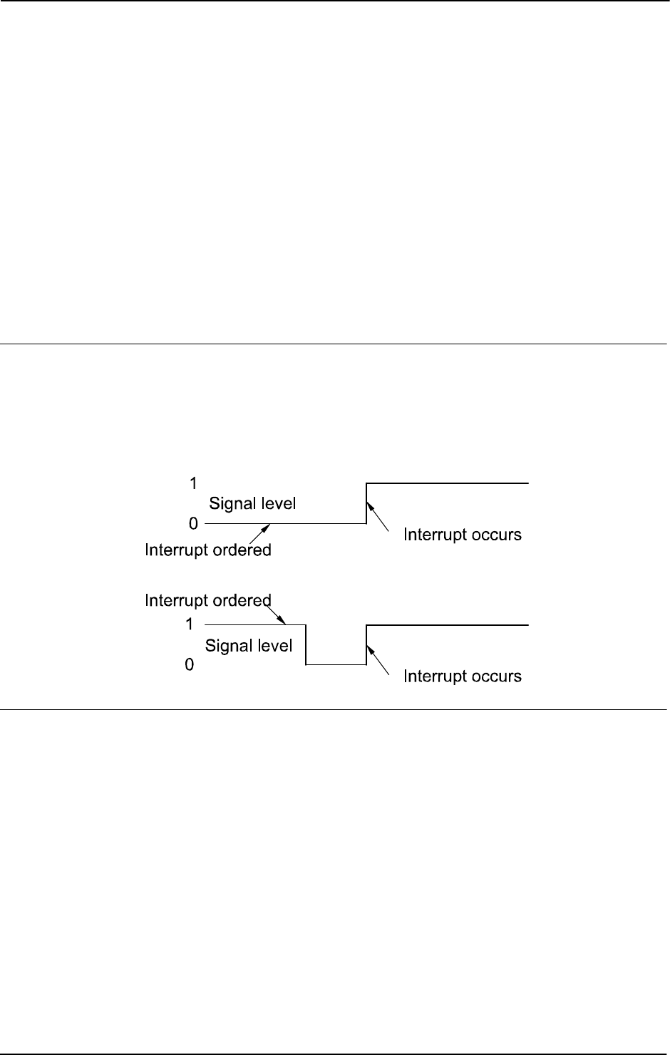
1 Instructions
1.76. ISignalDO - Interrupts from a digital output signal
RobotWare - OS
3HAC 16581-1 Revision: J190
© Copyright 2004-2010 ABB. All rights reserved.
TriggValue
Data type: dionum
The value to which the signal must change for an interrupt to occur.
The value is specified as 0 or 1 or as a symbolic value (e.g.
high/low). The signal is edge-
triggered upon changeover to 0 or 1.
TriggValue 2 or symbolic value edge can be used for generation of interrupts on both
positive flank (0 -> 1) and negative flank (1 -> 0).
Interrupt
Data type: intnum
The interrupt identity. This should have previously been connected to a trap routine by means
of the instruction
CONNECT.
Program execution
When the signal assumes the specified value 0 or 1, a call is made to the corresponding trap
routine. When this has been executed program execution continues from where the interrupt
occurred.
If the signal changes to the specified value before the interrupt is ordered no interrupt occurs.
Interrupts from a digital output signal at signal level 1 is illustrated in the figure below.
xx0500002190
Error handling
Following recoverable error can be generated. The error can be handled in an error handler.
The system variable
ERRNO will be set to:
ERR_NORUNUNIT
if there is no contact with the unit.
Continued
Continues on next page

1 Instructions
1.76. ISignalDO - Interrupts from a digital output signal
RobotWare - OS
1913HAC 16581-1 Revision: J
© Copyright 2004-2010 ABB. All rights reserved.
Limitations
The same variable for interrupt identity cannot be used more than once without first deleting
it. Interrupts should therefore be handled as shown in one of the alternatives below.
PROC main ( )
VAR intnum sig1int;
CONNECT sig1int WITH iroutine1;
ISignalDO do1, 1, sig1int;
WHILE TRUE DO
...
ENDWHILE
ENDPROC
All activation of interrupts is done at the beginning of the program. These beginning
instructions are then kept outside the main flow of the program.
PROC main ( )
VAR intnum sig1int;
CONNECT sig1int WITH iroutine1;
ISignalDO do1, 1, sig1int;
...
IDelete sig1int;
ENDPROC
The interrupt is deleted at the end of the program and is then reactivated. It should be noted,
in this case, that the interrupt is inactive for a short period.
Syntax
ISignalDO
[ ’\’ Single ] | [ ’\’ SingleSafe ] ’,’
[ Signal ’:=’ ] < variable (VAR) of signaldo > ’,’
[ TriggValue’ :=’ ] < expression (IN) of dionum > ’,’
[ Interrupt’ :=’ ] < variable (VAR) of intnum > ’;’
Related information
For information about See
Summary of interrupts Technical reference manual - RAPID
overview, section RAPID Summary -
Interrupts
Interrupt from an input signal ISignalDI - Orders interrupts from a digital
input signal on page 186
More information on interrupt management Technical reference manual - RAPID
overview, section Basic Characteristics-
Interrupts
Interrupt identity intnum - Interrupt identity on page 1125
Continued

1 Instructions
1.77. ISignalGI - Orders interrupts from a group of digital input signals
RobotWare - OS
3HAC 16581-1 Revision: J192
© Copyright 2004-2010 ABB. All rights reserved.
1.77. ISignalGI - Orders interrupts from a group of digital input signals
Usage
ISignalGI (Interrupt Signal Group Digital In) is used to order and enable interrupts from
a group of digital input signals.
Basic examples
Basic examples of the instruction
ISignalGI are illustrated below.
Example 1
VAR intnum sig1int;
CONNECT sig1int WITH iroutine1;
ISignalGI gi1,sig1int;
Orders an interrupt when a digital input group signal changes value.
Arguments
ISignalGI [ \Single ] | [ \SingleSafe ] Signal Interrupt
[ \Single ]
Data type: switch
Specifies whether the interrupt is to occur once or cyclically.
If the argument
Single is set, the interrupt occurs once at the most. If the Single and
SingleSafe arguments is omitted, an interrupt will occur each time its condition is satisfied.
[ \SingleSafe ]
Data type: switch
Specifies that the interrupt is single and safe. For definition of single, see description of
Single argument. A safe interrupt can not be put in sleep with instruction ISleep. The safe
interrupt event will be queued at program stop and stepwise execution, and when starting in
continious mode again, the interrupt will be executed. The only time a safe interrupt will be
thrown is when the interrupt queue is full. Then an error will be reported. The interrupt will
not survive program reset, e.g. PP to main.
Signal
Data type: signalgi
The name of the group input signal that generates interrupts.
Interrupt
Data type: intnum
The interrupt identity. This should have previously been connected to a trap routine by means
of the instruction
CONNECT.
Program execution
When the group signal changes value a call is made to the corresponding trap routine. When
this has been executed program execution continues from where the interrupt occurred.
If the signal changes before the interrupt is ordered no interrupt occurs.
Continues on next page

1 Instructions
1.77. ISignalGI - Orders interrupts from a group of digital input signals
RobotWare - OS
1933HAC 16581-1 Revision: J
© Copyright 2004-2010 ABB. All rights reserved.
Error handling
Following recoverable error can be generated. The error can be handled in an error handler.
The system variable
ERRNO will be set to:
ERR_NORUNUNIT
if there is no contact with the unit.
Limitations
Maximum number of signals that can be used for a group is 32.
Numeric value condition can not be used in the instruction to specify that an interrupt should
occur on changes to that specific value. This must be handled in the user program by reading
the group signal value at execution of the
TRAP.
The interrupts are generated as bit interrupts, e.g. interrupts on single digital input signal
change within the group. If the bits in the group signal change value with a delay between
settings, several interrupts will be generated. Knowledege about how the I/O board works is
necessary to get right functionality when using
ISignalGI. If several interrupts are
generated at group input settings, use instead
ISignalDI on a strobe signal that are set when
all bits in the group signal have been set.
The same variable for interrupt identity cannot be used more than once without first deleting
it. Interrupts should therefore be handled as shown in one of the alternatives below.
PROC main ( )
VAR intnum sig1int;
CONNECT sig1int WITH iroutine1;
ISignalGI gi1, sig1int;
WHILE TRUE DO
...
ENDWHILE
ENDPROC
All activation of interrupts is done at the beginning of the program. These beginning
instructions are then kept outside the main flow of the program.
PROC main ( )
VAR intnum sig1int;
CONNECT sig1int WITH iroutine1;
ISignalGI gi1, sig1int;
...
IDelete sig1int;
ENDPROC
The interrupt is deleted at the end of the program and is then reactivated. It should be noted,
in this case, that the interrupt is inactive for a short period.
Syntax
ISignalGI
[ ’\’ Single ] | [ ’\’ SingleSafe ] ’,’
[ Signal ’:=’ ] < variable (VAR) of signalgi > ’,’
[ Interrupt’:=’ ] < variable (VAR) of intnum > ’;’
Continued
Continues on next page

1 Instructions
1.77. ISignalGI - Orders interrupts from a group of digital input signals
RobotWare - OS
3HAC 16581-1 Revision: J194
© Copyright 2004-2010 ABB. All rights reserved.
Related information
For information about See
Summary of interrupts Technical reference manual - RAPID overview,
section RAPID Summary - Interrupts
Interrupt from an input signal ISignalDI - Orders interrupts from a digital input signal
on page 186
Interrupt from group output signals ISignalGO - Orders interrupts from a group of digital
output signals on page 195
More information on interrupt
management
Technical reference manual - RAPID overview,
section Basic Characteristics - Interrupts
Interrupt identity intnum - Interrupt identity on page 1125
Continued

1 Instructions
1.78. ISignalGO - Orders interrupts from a group of digital output signals
RobotWare - OS
1953HAC 16581-1 Revision: J
© Copyright 2004-2010 ABB. All rights reserved.
1.78. ISignalGO - Orders interrupts from a group of digital output signals
Usage
ISignalGO (Interrupt Signal Group Digital Out) is used to order and enable interrupts from
a group of digital output signals.
Basic examples
Basic examples of the instruction
ISignalGO are illustrated below.
Example 1
VAR intnum sig1int;
CONNECT sig1int WITH iroutine1;
ISignalGO go1,sig1int;
Orders an interrupt when a digital output group signal change value.
Arguments
ISignalGO [ \Single ] | [ \SingleSafe ] Signal Interrupt
[ \Single ]
Data type: switch
Specifies whether the interrupt is to occur once or cyclically.
If the argument \
Single is set, the interrupt occurs once at the most. If the Single and
SingleSafe arguments is omitted, an interrupt will occur each time its condition is satisfied.
[ \SingleSafe ]
Data type: switch
Specifies that the interrupt is single and safe. For definition of single, see description of
Single argument. A safe interrupt can not be put in sleep with instruction ISleep. The safe
interrupt event will be queued at program stop and stepwise execution, and when starting in
continious mode again, the interrupt will be executed. The only time a safe interrupt will be
thrown is when the interrupt queue is full. Then an error will be reported. The interrupt will
not survive program reset, e.g. PP to main.
Signal
Data type: signalgo
The name of the group output signal that generates interrupts.
Interrupt
Data type: intnum
The interrupt identity. This should have previously been connected to a trap routine by means
of the instruction
CONNECT.
Program execution
When the group signal changes value a call is made to the corresponding trap routine. When
this has been executed program execution continues from where the interrupt occurred.
If the signal changes before the interrupt is ordered no interrupt occurs.
Continues on next page

1 Instructions
1.78. ISignalGO - Orders interrupts from a group of digital output signals
RobotWare - OS
3HAC 16581-1 Revision: J196
© Copyright 2004-2010 ABB. All rights reserved.
Error handling
Following recoverable error can be generated. The error can be handled in an error handler.
The system variable
ERRNO will be set to:
ERR_NORUNUNIT
if there is no contact with the unit.
Limitations
Maximum number of signals that can be used for a group is 32.
Numeric value condition can not be used in the instruction to specify that an interrupt should
occur on changes to that specific value. This must be handled in the user program by reading
the group signal value at execution of the
TRAP.
The same variable for interrupt identity cannot be used more than once without first deleting
it. Interrupts should therefore be handled as shown in one of the alternatives below.
PROC main ( )
VAR intnum sig1int;
CONNECT sig1int WITH iroutine1;
ISignalGO go1, sig1int;
WHILE TRUE DO
...
ENDWHILE
ENDPROC
All activation of interrupts is done at the beginning of the program. These beginning
instructions are then kept outside the main flow of the program.
PROC main ( )
VAR intnum sig1int;
CONNECT sig1int WITH iroutine1;
ISignalGO go1, sig1int;
...
IDelete sig1int;
ENDPROC
The interrupt is deleted at the end of the program and is then reactivated. It should be noted,
in this case, that the interrupt is inactive for a short period.
Syntax
ISignalGO
[ ’\’ Single ] | [ ’\’ SingleSafe ] ’,’
[ Signal ’:=’ ] < variable (VAR) of signalgo > ’,’
[ Interrupt’:=’ ] < variable (VAR) of intnum > ’;’
Continued
Continues on next page

1 Instructions
1.78. ISignalGO - Orders interrupts from a group of digital output signals
RobotWare - OS
1973HAC 16581-1 Revision: J
© Copyright 2004-2010 ABB. All rights reserved.
Related information
For information about See
Summary of interrupts Technical reference manual - RAPID
overview, section RAPID Summary -
Interrupts
Interrupt from an output signal ISignalDO - Interrupts from a digital output
signal on page 189
Interrupt from group input signals ISignalGI - Orders interrupts from a group of
digital input signals on page 192
More information on interrupt management Technical reference manual - RAPID
overview, section Basic Characteristics -
Interrupts
Interrupt identity intnum - Interrupt identity on page 1125
Continued

1 Instructions
1.79. ISleep - Deactivates an interrupt
RobotWare - OS
3HAC 16581-1 Revision: J198
© Copyright 2004-2010 ABB. All rights reserved.
1.79. ISleep - Deactivates an interrupt
Usage
ISleep (Interrupt Sleep) is used to deactivate an individual interrupt temporarily.
During the deactivation time any generated interrupts of the specified type are discarded
without any trap execution.
Basic examples
Basic examples of the instruction are illustrated below.
See also More examples on page 198.
Example 1
ISleep sig1int;
The interrupt sig1int is deactivated.
Arguments
ISleep Interrupt
Interrupt
Data type: intnum
The variable (interrupt identity) of the interrupt.
Program execution
Any generated interrupts of the specified type are discarded without any trap execution until
the interrupt has been re-activated by means of the instruction
IWatch. Interrupts which are
generated while
ISleep is in effect are ignored.
More examples
More examples of the instruction
ISleep are illustrated below.
Example 1
VAR intnum timeint;
CONNECT timeint WITH check_serialch;
ITimer 60, timeint;
...
ISleep timeint;
WriteBin ch1, buffer, 30;
IWatch timeint;
...
TRAP check_serialch
WriteBin ch1, buffer, 1;
IF ReadBin(ch1\Time:=5) < 0 THEN
TPWrite "The serial communication is broken";
EXIT;
ENDIF
ENDTRAP
Continues on next page

1 Instructions
1.79. ISleep - Deactivates an interrupt
RobotWare - OS
1993HAC 16581-1 Revision: J
© Copyright 2004-2010 ABB. All rights reserved.
Communication across the ch1 serial channel is monitored by means of interrupts which are
generated every
60 seconds. The trap routine checks whether the communication is working.
When, however, communication is in progress these interrupts are not permitted.
Error handling
Interrupts which have neither been ordered nor enabled are not permitted. If the interrupt
number is unknown the system variable
ERRNO will be set to ERR_UNKINO (see errnum -
Error number on page 1108). If trying to deactivate a safe interrupt temporarily with
ISleep,
the system variable
ERRNO is set to ERR_INOISSAFE. These errors can be handled in an error
handler.
Syntax
ISleep
[ Interrupt ‘:=’ ] < variable (VAR) of intnum > ‘;’
Related information
For information about See
Summary of interrupts Technical reference manual - RAPID overview,
section RAPID summary - Interrupts
Enabling an interrupt IWatch - Activates an interrupt on page 205
Disabling all interrupts IDisable - Disables interrupts on page 124
Cancelling an interrupt IDelete - Cancels an interrupt on page 123
Continued

1 Instructions
1.80. ITimer - Orders a timed interrupt
RobotWare - OS
3HAC 16581-1 Revision: J200
© Copyright 2004-2010 ABB. All rights reserved.
1.80. ITimer - Orders a timed interrupt
Usage
ITimer (Interrupt Timer) is used to order and enable a timed interrupt.
This instruction can be used, for example, to check the status of peripheral equipment once
every minute.
Basic examples
Basic examples of the instruction
ITimer are illustrated below.
See also More examples on page 201.
Example 1
VAR intnum timeint;
CONNECT timeint WITH iroutine1;
ITimer 60, timeint;
Orders an interrupt that is to occur cyclically every 60 seconds. A call is then made to the trap
routine
iroutine1.
Example 2
ITimer \Single, 60, timeint;
Orders an interrupt that is to occur once, after 60 seconds.
Arguments
ITimer [ \Single ] | [ \SingleSafe ] Time Interrupt
[ \Single ]
Data type: switch
Specifies whether the interrupt is to occur once or cyclically.
If the argument
Single is set, the interrupt occurs only once. If the Single and
SingleSafe arguments is omitted, an interrupt will occur each time at the specified time.
[ \SingleSafe ]
Data type: switch
Specifies that the interrupt is single and safe. For definition of single, see description of
Single argument. A safe interrupt can not be put in sleep with instruction ISleep. The safe
interrupt event will be queued at program stop and stepwise execution, and when starting in
continious mode again, the interrupt will be executed.
Time
Data type: num
The amount of time that must lapse before the interrupt occurs.
The value is specified in seconds. If
Single or SingleSafe is set this time may not be less
than 0.01 seconds. The corresponding time for cyclical interrupts is 0.1 seconds.
Interrupt
Data type: intnum
The variable (interrupt identity) of the interrupt. This should have previously been connected
to a trap routine by means of the instruction
CONNECT.
Continues on next page

1 Instructions
1.80. ITimer - Orders a timed interrupt
RobotWare - OS
2013HAC 16581-1 Revision: J
© Copyright 2004-2010 ABB. All rights reserved.
Program execution
The corresponding trap routine is automatically called at a given time following the interrupt
order. When this has been executed program execution continues from where the interrupt
occurred.
If the interrupt occurs cyclically a new computation of time is started from when the interrupt
occurs.
More examples
More examples of the instruction
ITimer are illustrated below.
Example 1
VAR intnum timeint;
CONNECT timeint WITH check_serialch;
ITimer 60, timeint;
...
TRAP check_serialch
WriteBin ch1, buffer, 1;
IF ReadBin(ch1\Time:=5) < 0 THEN
TPWrite "The serial communication is broken";
EXIT;
ENDIF
ENDTRAP
Communication across the ch1 serial channel is monitored by means of interrupts which are
generated every
60 seconds. The trap routine checks whether the communication is working.
If it is not program execution is terminated and an error message appears.
Limitations
The same variable for interrupt identity cannot be used more than once without being first
deleted. See Instructions -
ISignalDI.
Syntax
ITimer
[ ’\’ Single ] | [ ’\’ SingleSafe ] ’,’
[ Time ’:=’ ] < expression (IN) of num >’,’
[ Interrupt’ :=’ ] < variable (VAR) of intnum > ’;’
Related information
For information about See
Summary of interrupts Technical reference manual - RAPID
overview, section RAPID summary -
Interrupts
More information on interrupt management Technical reference manual - RAPID
overview, section Basic Characteristics-
Interrupts
Continued

1 Instructions
1.81. IVarValue - orders a variable value interrupt
Optical Tracking
3HAC 16581-1 Revision: J202
© Copyright 2004-2010 ABB. All rights reserved.
1.81. IVarValue - orders a variable value interrupt
Usage
IVarValue (Interrupt Variable Value) is used to order and enable an interrupt when the value
of a variable accessed via the serial sensor interface has been changed.
This instruction can be used, for example, to get seam volume or gap values from a seam
tracker.
Basic examples
Basic examples of the instruction
IVarValue are illustrated below.
Example 1
LOCAL PERS num
adptVlt{25}:=[1,1.2,1.4,1.6,1.8,2,2.16667,2.33333,2.5,...];
LOCAL PERS num
adptWfd{25}:=[2,2.2,2.4,2.6,2.8,3,3.16667,3.33333,3.5,...];
LOCAL PERS num
adptSpd{25}:=10,12,14,16,18,20,21.6667,23.3333,25[,...];
LOCAL CONST num GAP_VARIABLE_NO:=11;
PERS num gap_value;
VAR intnum IntAdap;
PROC main()
! Setup the interrupt. The trap routine AdapTrp will be called
! when the gap variable with number ´GAP_VARIABLE_NO’ in the
!sensor interface has been changed. The new value will be
! available in the PERS gp_value variable.
! Connect to the sensor device "sen1:" (defined in sio.cfg).
SenDevice "sen1:";
CONNECT IntAdap WITH AdapTrp;
IVarValue "sen1:", GAP_VARIABLE_NO, gap_value, IntAdap;
! Start welding
ArcL\On,*,v100,adaptSm,adaptWd,adaptWv,z10,tool\j\Track:=track;
ArcL\On,*,v100,adaptSm,adaptWd,adaptWv,z10,tool\j\Track:=track;
ENDPROC
Continues on next page

1 Instructions
1.81. IVarValue - orders a variable value interrupt
Optical Tracking
2033HAC 16581-1 Revision: J
© Copyright 2004-2010 ABB. All rights reserved.
TRAP AdapTrap
VAR num ArrInd;
!Scale the raw gap value received
ArrInd:=ArrIndx(gap_value);
! Update active welddata PERS variable ‘adaptWd’ with new data
! from the arrays of predefined parameter arrays. The scaled gap
! value is used as index in the voltage, wirefeed and
! speed arrays.
adaptWd.weld_voltage:=adptVlt{ArrInd};
adaptWd.weld_wirefeed:=adptWfd{ArrInd};
adaptWd.weld_speed:=adptSpd{ArrInd};
!Request a refresh of AW parameters using the new data i adaptWd
ArcRefresh;
ENDTRAP
Arguments
IVarValue device VarNo Value Interrupt [ \Unit ] [ \DeadBand ]
device
Data type: string
The I/O device name configured in sio.cfg for the sensor used.
VarNo
Data type: num
The number of the variable to be supervised.
Value
Data type: num
A PERS variable which will hold the new value of VarNo.
Interrupt
Data type: intnum
The variable (interrupt identity) of the interrupt. This should have previously been connected
to a trap routine by means of the instruction
CONNECT.
[ \Unit ]
Data type: num
Scale factor with which the sensor value for VarNo is multiplied before check and before it
is saved in
Value.
[ \DeadBand ]
Data type: num
If the value for Varno, returned by the sensor, is within +/- DeadBand no interrupt is
generated.
Continued
Continues on next page

1 Instructions
1.81. IVarValue - orders a variable value interrupt
Optical Tracking
3HAC 16581-1 Revision: J204
© Copyright 2004-2010 ABB. All rights reserved.
Program execution
The corresponding trap routine is automatically called at a given time following the interrupt
order. When this has been executed program execution continues from where the interrupt
occurred.
Limitations
The same variable for interrupt identity cannot be used more than five times without first
being deleted.
CAUTION!
Too high interrupt frequency will stall the whole RAPID execution.
Syntax
IVarValue
[ device ’:=’ ] < expression (IN) of string>’,’
[ VarNo ’:=’ ] < expression (IN) of num >’,’
[ Value ’:=’ ] < persistent (PERS) of num >’,’
[ Interrupt’ :=’ ] < variable (VAR) of intnum > ’,’
[ ’\’ Unit’ :=’ ] < expression (IN) of num >’,’
[ ’\’ DeadBand’ :=’ ] < expression (IN) of num > ’;’
Related information
For information about See
Connect to a sensor device SenDevice - connect to a sensor device on page
425
Summary of interrupts Technical reference manual - RAPID overview,
section RAPID summary - Interrupts
More information on interrupt
management
Technical reference manual - RAPID overview,
section Basic characteristics - Interrupts
Optical Tracking Application manual - Continuous application
platform
Optical Tracking Art Application manual - Arc and Arc Sensor
Continued

1 Instructions
1.82. IWatch - Activates an interrupt
RobotWare - OS
2053HAC 16581-1 Revision: J
© Copyright 2004-2010 ABB. All rights reserved.
1.82. IWatch - Activates an interrupt
Usage
IWatch (Interrupt Watch) is used to activate an interrupt which was previously ordered but
was deactivated with
ISleep.
Basic examples
Basic examples of the instruction
IWatch are illustrated below.
See also More examples on page 205.
Example 1
IWatch sig1int;
The interrupt sig1int that was previously deactivated is activated.
Arguments
IWatch Interrupt
Interrupt
Data type: intnum
Variable (interrupt identity) of the interrupt.
Program execution
Re-activates interrupts of the specified type once again. However, interrupts generated during
the time the
ISleep instruction was in effect are ignored.
More examples
More examples of the instruction
IWatch are illustrated below.
Example 1
VAR intnum sig1int;
CONNECT sig1int WITH iroutine1;
ISignalDI di1,1,sig1int;
...
ISleep sig1int;
weldpart1;
IWatch sig1int;
During execution of the weldpart1 routine no interrupts are permitted from the signal di1.
Error handling
Interrupts which have not been ordered are not permitted. If the interrupt number is unknown
the system variable
ERRNO is set to ERR_UNKINO (see errnum - Error number on page 1108).
The error can be handled in the error handler.
Syntax
IWatch
[ Interrupt ‘:=’ ] < variable (VAR) of intnum > ‘;’
Continues on next page

1 Instructions
1.82. IWatch - Activates an interrupt
RobotWare - OS
3HAC 16581-1 Revision: J206
© Copyright 2004-2010 ABB. All rights reserved.
Related information
For information about See
Summary of interrupts Technical reference manual - RAPID
overview, section RAPID summary -
Interrupts
Deactivating an interrupt ISleep - Deactivates an interrupt on page 198
Continued

1 Instructions
1.83. Label - Line name
RobotWare - OS
2073HAC 16581-1 Revision: J
© Copyright 2004-2010 ABB. All rights reserved.
1.83. Label - Line name
Usage
Label is used to name a line in the program. Using the GOTO instruction this name can then
be used to move program execution within the same routine.
Basic examples
Basic examples of the instruction
Label are illustrated below.
Example 1
GOTO next;
...
next:
Program execution continues with the instruction following next.
Arguments
Label:
Label
Identifier
The name you wish to give the line.
Program execution
Nothing happens when you execute this instruction.
Limitations
The label must not be the same as
• any other label within the same routine.
• any data name within the same routine.
A label hides global data and routines with the same name within the routine it is located in.
Syntax
(EBNF)
<identifier>’:’
Related information
For information about See
Identifiers Technical reference manual - RAPID overview,
section Basic characteristics - Basic elements
Moving program execution to a label GOTO - Goes to a new instruction on page 117

1 Instructions
1.84. Load - Load a program module during execution
RobotWare - OS
3HAC 16581-1 Revision: J208
© Copyright 2004-2010 ABB. All rights reserved.
1.84. Load - Load a program module during execution
Usage
Load is used to load a program module into the program memory during execution.
The loaded program module will be added to the already existing modules in the program
memory.
A program or system module can be loaded in static (default) or dynamic mode.
Both static and dynamic loaded modules can be unloaded by the instruction
UnLoad.
Static mode
The following table describes how different operations affect static loaded program or system
modules.
Dynamic mode
The following table describes how different operations affect dynamic loaded program or
system modules.
Basic examples
Basic examples of the instruction
Load are illustrated below.
See also More examples on page 210.
Example 1
Load \Dynamic, diskhome \File:="PART_A.MOD";
Loads the program module PART_A.MOD from the diskhome into the program memory.
diskhome is a predefined string constant "HOME:". Load the program module in the
dynamic mode.
Example 2
Load \Dynamic, diskhome \File:="PART_A.MOD";
Load \Dynamic, diskhome \File:="PART_B.MOD" \CheckRef;
Loads the program module PART_A.MOD into the program memory, then PART_B.MOD is
loaded. If
PART_A.MOD contains references to PART_B.MOD, \CheckRef can be used to
check for unresolved references only when the last module is loaded. IF \
CheckRef is used
on
PART_A.MOD, a link error would occur and the module would not be loaded.
Type of module
Set PP to main from
FlexPendant
Open new RAPID program
Program Module Not affected Unloaded
System Module Not affected Not affected
Type of module
Set PP to main from
FlexPendant
Open new RAPID program
Program Module Unloaded Unloaded
System Module Unloaded Unloaded
Continues on next page

1 Instructions
1.84. Load - Load a program module during execution
RobotWare - OS
2093HAC 16581-1 Revision: J
© Copyright 2004-2010 ABB. All rights reserved.
Arguments
Load [\Dynamic] FilePath [\File] [\CheckRef]
[\Dynamic]
Data type: switch
The switch enables load of a module in dynamic mode. Otherwise the load is in static mode.
FilePath
Data type: string
The file path and the file name to the file that will be loaded into the program memory. The
file name shall be excluded when the argument
\File is used.
[\File]
Data type: string
When the file name is excluded in the argument FilePath then it must be defined with this
argument.
[\CheckRef]
Data type: switch
Check after loading of the module for unsolved references in the program task. If not used no
check for unsolved references are done.
Program execution
Program execution waits for the program module to finish loading before proceeding with the
next instruction.
Unresolved references will always be accepted for the loading operation, if parameter
\CheckRef is not used, but it will be a run time error on execution of an unresolved
reference.
After the program module is loaded it will be linked and initialized. The initialization of the
loaded module sets all variables at module level to their unit values.
If any error from the loading operation, including unresolved references if use of switch
\CheckRef, the loaded module will not be available any more in the program memory.
To obtain a good program structure that is easy to understand and maintain, all loading and
unloading of program modules should be done from the main module which is always present
in the program memory during execution.
For loading of program that contains a main procedure to a main program (with another main
procedure), see example in More examples on page 210 below.
Continued
Continues on next page
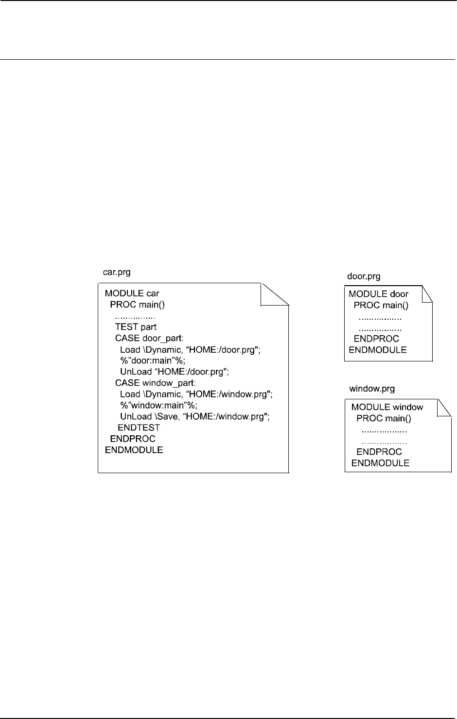
1 Instructions
1.84. Load - Load a program module during execution
RobotWare - OS
3HAC 16581-1 Revision: J210
© Copyright 2004-2010 ABB. All rights reserved.
More examples
More examples of how to use the instruction
Load are illustrated below.
More general examples
Load \Dynamic, "HOME:/DOORDIR/DOOR1.MOD";
Loads the program module DOOR1.MOD from HOME: at the directory DOORDIR into the
program memory. The program module is loaded in the dynamic mode.
Load "HOME:" \File:="DOORDIR/DOOR1.MOD";
Same as above but another syntax, and the module is loaded in the static mode.
Load\Dynamic, "HOME:/DOORDIR/DOOR1.MOD";
%"routine_x"%;
UnLoad "HOME:/DOORDIR/DOOR1.MOD";
Procedure routine_x, will be binded during execution (late binding).
Loaded program contains a main procedure
xx0500002104
The above example shows how you can load a program which includes a main procedure.
This program can have been developed and tested separately and later loaded with
Load or
StartLoad... WaitLoad into the system using some type of main program framework. In
this example
car.prg, which loads other programs door.prg or window.prg.
In the program
car.prg you load door.prg or window.prg located at "HOME:". Because
the
main procedures in door.prg and window.prg after the loading are considered
LOCAL in the module by the system, the procedure calls are made in the following way:
%"door:main"% or %"window: main"%. This syntax is used when you want to get access
to LOCAL procedures in other modules in this example procedure
main in module door or
module
window.
Unloading the modules with
\Save argument will again make the main procedures global in
the saved program.
If you, when the module
car or window are loaded in the system, set program pointer to main
from any part of the program, the program pointer will always be set to the global
main
procedure in the main program,
car.prg in this example.
Continued
Continues on next page

1 Instructions
1.84. Load - Load a program module during execution
RobotWare - OS
2113HAC 16581-1 Revision: J
© Copyright 2004-2010 ABB. All rights reserved.
Limitations
Avoid ongoing robot movements during the loading.
Error handling
If the file specified in the
Load instruction cannot be found the system variable ERRNO is set
to
ERR_FILNOTFND at execution.
If some other type of problems to read the file to load the system variable
ERRNO will be set
to
ERR_IOERROR.
If the module cannot be loaded because the program memory is full the system variable
ERRNO is set to ERR_PRGMEMFULL.
If the module is already loaded into the program memory the system variable
ERRNO is set to
ERR_LOADED.
If the loaded module contains syntax errors the system variable
ERRNO is set to ERR_SYNTAX.
If the loaded module result in fatal link errors the system variable
ERRNO is set to
ERR_LINKREF.
If
Load is used with the switch \CheckRef to check for any reference error and the program
memory contains unresolved references the system variable
ERRNO is set to ERR_LINKREF.
These errors can then be handled in the
ERROR handler. If some of these error occurs the actual
module will be unloaded and will not be available in the
ERROR handler.
Syntax
Load
[´\´Dynamic´,´]
[FilePath´:=´]<expression (IN) of string>
[´\´File´:=´ <expression (IN) of string>]
[´\´CheckRef]´;´
Related information
For information about See
Unload a program module UnLoad - UnLoad a program module during
execution on page 655
Load a program module in parallel with
another program execution
StartLoad - Load a program module during
execution on page 482
WaitLoad - Connect the loaded module to the
task on page 682
Check program references CheckProgRef - Check program references
on page 37
Continued

1 Instructions
1.85. LoadId - Load identification of tool or payload
RobotWare-OS
3HAC 16581-1 Revision: J212
© Copyright 2004-2010 ABB. All rights reserved.
1.85. LoadId - Load identification of tool or payload
Usage
LoadId (Load Identification) can be used for load identification of tool (also gripper tool if
roomfix TCP) or payload (activates with instruction
GripLoad) by executing a user defined
RAPID program.
NOTE!
An easier way to identify the tool load or payload is to use the interactive dialogue RAPID
program
LoadIdentify. This program can be started from the menu
Program Editor/Debug/Call Service Rout./LoadIdentify.
Basic examples
Basic examples of the instruction
LoadId are illustrated below.
See also More examples on page 216.
Example 1
VAR bool invalid_pos := TRUE;
VAR jointtarget joints;
VAR bool valid_joints{12};
CONST speeddata low_ori_speed := [20, 5, 20, 5];
VAR bool slow_test_flag := TRUE;
PERS tooldata grip3 := [ TRUE, [[97.4, 0, 223.1], [0.924, 0, 0.383
,0]], [0, [0, 0, 0], [1, 0, 0, 0], 0, 0, 0]];
! Check if valid robot type
IF ParIdRobValid(TOOL_LOAD_ID) <> ROB_LOAD_VAL THEN
EXIT;
ENDIF
! Check if valid robot position
WHILE invalid_pos = TRUE DO
joints := CJointT();
IF ParIdPosValid (TOOL_LOAD_ID, joints, valid_joints) = TRUE
THEN
! Valid position
invalid_pos := FALSE;
ELSE
! Invalid position
! Adjust the position by program movements (horizontal tilt
house)
MoveAbsJ joints, low_ori_speed, fine, tool0;
ENDIF
ENDWHILE
! Do slow test for check of free working area
IF slow_test_flag = TRUE THEN
LoadId TOOL_LOAD_ID, MASS_WITH_AX3, grip3 \SlowTest;
ENDIF
! Do measurement and update all load data in grip3
LoadId TOOL_LOAD_ID, MASS_WITH_AX3, grip3;
Continues on next page

1 Instructions
1.85. LoadId - Load identification of tool or payload
RobotWare-OS
2133HAC 16581-1 Revision: J
© Copyright 2004-2010 ABB. All rights reserved.
Load identification of tool grip3.
Condition
The following conditions should be fulfilled before load measurements with
LoadId:
• Make sure that all loads are correctly mounted on the robot
• Check whether valid robot type with ParIdRobValid
• Check whether valid position with ParIdPosValid:
- Axes 3, 5, and 6 not close to their corresponding working range
- Tilt housing almost horizontal, i.e. that axis 4 is in zero position
• The following data should be defined in system parameters and in arguments to
LoadId before running LoadId
The table below illustrates the load identification of tool.
The table below illustrates the load identification of payload.
• Operating mode and speed override:
- Slow test in manual mode reduced speed
- Load measurements in automatic mode (or manual mode full speed) with speed
override 100%
Load identification
modes /
Defined data before
LoadId
Moving
TCP Mass
Known
Moving
TCP Mass
Unknown
Roomfix
TCP Mass
Known
Roomfix
TCP Mass
Unknown
Upper arm load
(System parameter)
Defined Defined
Mass in tool Defined Defined
Load identification
modes /
Defined data before
LoadId
Moving
TCP Mass
Known
Moving
TCP Mass
Unknown
Roomfix
TCP Mass
Known
Roomfix
TCP Mass
Unknown
Upper arm load
(System parameters)
Defined Defined
Load data in tool Defined Defined Defined Defined
Mass in payload Defined Defined
Tool frame in tool Defined Defined
User frame in work object Defined Defined
Object frame in work object Defined Defined
Continued
Continues on next page

1 Instructions
1.85. LoadId - Load identification of tool or payload
RobotWare-OS
3HAC 16581-1 Revision: J214
© Copyright 2004-2010 ABB. All rights reserved.
Arguments
LoadId ParIdType LoadIdType Tool [\PayLoad] [\WObj] [\ConfAngle]
[\SlowTest] [\Accuracy]
ParIdType
Data type: paridnum
Type of load identification as defined in the table below.
LoadIdType
Data type: loadidnum
Type of load identification as defined in the table below.
Tool
Data type: tooldata
Persistent variable for the tool to be identified. If argument \PayLoad is specified, the
persistent variable for the tool in use.
For load identification of tool, the following arguments
\PayLoad and \WObj should not be
specified.
[ \ PayLoad ]
Data type: loaddata
Persistent variable for the payload to be identified.
This option argument must always be specified for load identification of payload.
[ \ WObj ]
Data type: wobjdata
Persistent variable for the work object in use.
This option argument must always be specified for load identification of payload with
roomfix TCP.
Value Symbolic constant Comment
1 TOOL_LOAD_ID Identify tool load
2 PAY_LOAD_ID Identify payload (Ref. instruction GripLoad)
Value Symbolic constant Comment
1 MASS_KNOWN Known mass in tool or payload respectively. (Mass in
specified Tool or PayLoad must be specified)
2 MASS_WITH_AX3 Unknown mass in tool or payload respectively.
Identification of mass in tool or payload will be done
with movements of axis 3
Continued
Continues on next page
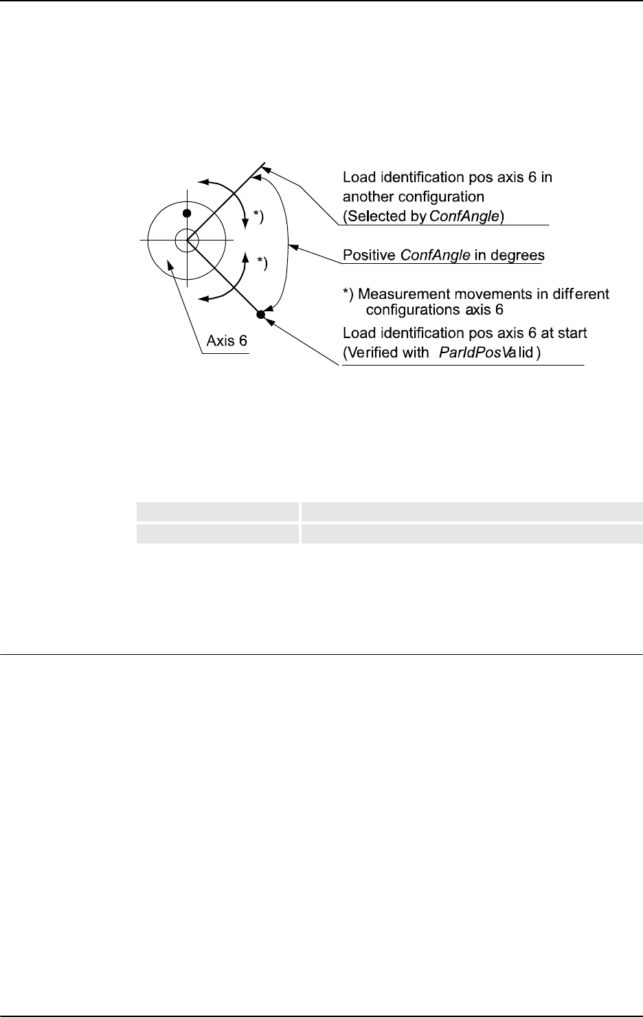
1 Instructions
1.85. LoadId - Load identification of tool or payload
RobotWare-OS
2153HAC 16581-1 Revision: J
© Copyright 2004-2010 ABB. All rights reserved.
[ \ ConfAngle ]
Data type: num
Option argument for specification of a specific configuration angle ± degrees to be used for
the parameter identification.
xx0500002198
Default + 90 degrees if this argument is not specified. Min. + or - 30 degrees. Optimum + or
- 90 degrees.
[ \ SlowTest ]
Data type: switch
Option argument to specify whether only slow test for checking of free working area should
be done. See table below:
[ \ Accuracy ]
Data type: num
Variable for output of calculated measurement accuracy in % for the whole load identification
calculation (100% means maximum accuracy).
Program execution
The robot will carry out a large number of relative small transport and measurement
movements on axes 5 and 6. For identification of mass, movements will also be made with
axis 3.
After all measurements, movements, and load calculations the load data is returned in
argument
Tool or PayLoad. The following load data is calculated:
• Mass in kg (if mass is unknown otherwise not affected)
• Center of gravity x, y, z, and axes of moment
• Inertia ix, iy, iz in kgm
LoadId ... \SlowTest Run only slow test
LoadId ... Run only measurement and update tool or payload
Continued
Continues on next page

1 Instructions
1.85. LoadId - Load identification of tool or payload
RobotWare-OS
3HAC 16581-1 Revision: J216
© Copyright 2004-2010 ABB. All rights reserved.
More examples
More examples of the instruction
LoadId are illustrated below.
Example 1
PERS tooldata grip3 := [ FALSE, [[97.4, 0, 223.1], [0.924, 0, 0.383
,0]], [6, [10, 10, 100], [0.5, 0.5, 0.5, 0.5], 1.2, 2.7,
0.5]];
PERS loaddata piece5 := [ 5, [0, 0, 0], [1, 0, 0, 0], 0, 0, 0];
PERS wobjdata wobj2 := [ TRUE, TRUE, "", [ [34, 0, -45], [0.5, -
0.5, 0.5 ,-0.5] ], [ [0.56, 10, 68], [0.5, 0.5, 0.5 ,0.5] ] ];
VAR num load_accuracy;
! Do measurement and update all payload data except mass in piece5
LoadId PAY_LOAD_ID, MASS_KNOWN, grip3 \PayLoad:=piece5
\WObj:=wobj2 \Accuracy:=load_accuracy;
TPWrite " Load accuracy for piece5 (%) = " \Num:=load_accuracy;
Load identification of payload piece5 with known mass in installation with roomfix TCP.
Limitations
Usually load identification of tool or payload for the robot is done with the service routine
LoadIdentify. It is also possible to do this identification with this RAPID instruction
LoadId. Before loading or executing the program with LoadId following modules must be
loaded to the system:
Load \Dynamic, "RELEASE:/system/mockit.sys";
Load \Dynamic, "RELEASE:/system/mockit1.sys";
It is not possible to restart the load identification movements after any type of stop such as
program stop, emergency stop, or power failure. The load identification movements must
then be started from the beginning.
Error handling
At any error during execution of the RAPID
NOSTEPIN routine LoadId, the system variable
ERRNO is set to ERR_PID_MOVESTOP, ERR_PID_RAISE_PP or ERR_LOADID_FATAL and the
program pointer is raised to the user call of
LoadId.
Syntax
LoadId
[ ParIdType ’:=’ ] <expression (IN) of paridnum>´,’
[ LoadIdType’ :=’ ] <expression (IN) of loadidnum> ´,’
[ Tool ’:=’ ] <persistent (PERS) of tooldata>
[ ‘\’ PayLoad’ :=’ <persistent (PERS) of loaddata> ]
[ ‘\’ WObj’ :=’ <persistent (PERS) of wobjdata> ]
[ ‘\’ ConfAngle’ :=’ <expression (IN) of num> ]
[ ´\’ SlowTest ]
[ ´\’ Accuracy’ :=’ <variable (VAR) of num> ] ´;’
Continued
Continues on next page

1 Instructions
1.85. LoadId - Load identification of tool or payload
RobotWare-OS
2173HAC 16581-1 Revision: J
© Copyright 2004-2010 ABB. All rights reserved.
Related information
For information about See
Predefined program Load Identify Operating manual - IRC5 with FlexPendant, section
Programming and testing - Service routines - Load-
Identify, load identification and service routines
Type of parameter identification paridnum - Type of parameter identification on page
1154
Result of ParIdRobValid paridvalidnum - Result of ParIdRobValid on page
1156
Type of load identification loadidnum - Type of load identification on page 1137
Valid robot type ParIdRobValid - Valid robot type for parameter iden-
tification on page 916
Valid robot position ParIdPosValid - Valid robot position for parameter
identification on page 913
Continued

1 Instructions
1.86. MakeDir - Create a new directory
RobotWare - OS
3HAC 16581-1 Revision: J218
© Copyright 2004-2010 ABB. All rights reserved.
1.86. MakeDir - Create a new directory
Usage
MakeDir is used to create a new directory. The user must have write and execute permission
for the parent directory under which the new directory is created.
Basic examples
Basic examples of the instruction
MakeDir are illustrated below.
Example 1
MakeDir "HOME:/newdir";
This example creates a new directory, called newdir, under HOME:
Arguments
MakeDir Path
Path
Data type:string
The name of the new directory specified with full or relative path.
Error handling
If the directory cannot be created the system variable
ERRNO is set to ERR_FILEACC. This
error can then be handled in the error handler.
Syntax
MakeDir
[ Path’:=’ ] < expression (IN) of string>’;’
Related information
For information about See
Remove a directory RemoveDir - Delete a directory on page 355
Rename a file RenameFile - Rename a file on page 357
Remove a file RemoveFile - Delete a file on page 356
Copy a file CopyFile - Copy a file on page 65
Check file type IsFile - Check the type of a file on page 878
Check file size FileSize - Retrieve the size of a file on page
842
Check file system size FSSize - Retrieve the size of a file system on
page 848

1 Instructions
1.87. ManLoadIdProc - Load identification of IRBP manipulators
RobotWare-OS
2193HAC 16581-1 Revision: J
© Copyright 2004-2010 ABB. All rights reserved.
1.87. ManLoadIdProc - Load identification of IRBP manipulators
Usage
ManLoadIdProc (Manipulator Load Identification Procedure) is used for load identification
of payload for external manipulators by executing a user defined RAPID program.
This instruction can only be used in the main task
T_ROB1 or, if in a MultiMove system, in
Motion tasks.
NOTE!
An easier way to identify the payload is to use the interactive dialogue RAPID program
ManLoadIdentify.This program can be started from the menu
Program Editor/Debug/Call Routine.../ManLoadIdentify.
Basic examples
Basic examples of the instruction
ManLoadIdProc are illustrated below.
PERS loaddata myload := [6,[0,0,0],[1,0,0,0],0,0,0];
VAR bool defined;
ActUnit STN1;
ManLoadIdProc \ParIdType := IRBP_L
\MechUnit := STN1
\PayLoad := myload
\ConfigAngle := 60
\AlreadyActive
\DefinedFlag := defined;
DeactUnit STN1;
Load identification of payload myload mounted on the mechanical unit STN1. The external
manipulator is of type
IRBP-L. The configuration angle is set to 60 degrees. The manipulator
is activated before the load identification and deactivated after. After the identification
myload has been updated and defined it is set to TRUE.
Arguments
ManLoadIdProc [\ParIdType] [\MechUnit] | [\MechUnitName]
[\AxisNumber] [\PayLoad] [\ConfigAngle] [\DeactAll] |
[\AlreadyActive] [DefinedFlag] [DoExit]
[ \ ParIdType ]
Data type: paridnum
Type of parameter identification. Predefined constants are found under the datatype
paridnum.
[ \ MechUnit ]
Data type: mecunit
Mechanical unit used for the load identification. Can not be used together with argument
\MechUnitName.
Continues on next page
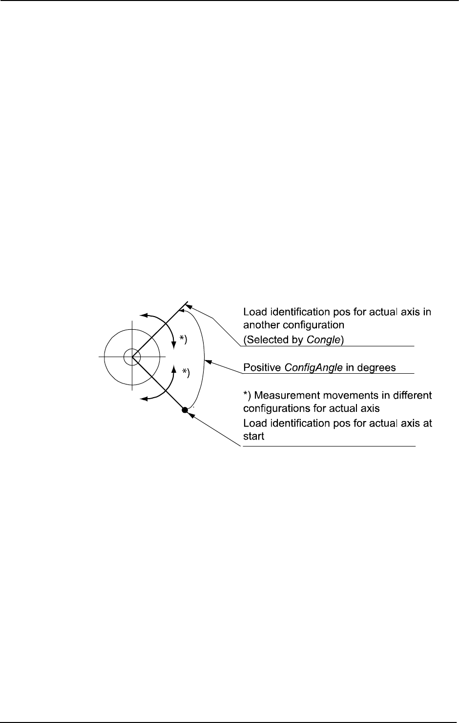
1 Instructions
1.87. ManLoadIdProc - Load identification of IRBP manipulators
RobotWare-OS
3HAC 16581-1 Revision: J220
© Copyright 2004-2010 ABB. All rights reserved.
[ \ MechUnitName ]
Data type: string
Mechanical unit used for the load identification given as a string. Can not be used together
with argument
\MechUnit.
[ \ AxisNumber ]
Data type: num
Axis number within the mechanical unit, which holds the load to be identified.
[ \ PayLoad ]
Data type: loaddata
Variable for the payload to be identified. The component mass must be specified.
This variable will be updated after the identification is done.
[ \ ConfigAngle ]
Data type: num
Specification of a specific configuration angle ± degrees to be used for the parameter
identification.
xx0500002197
Min. + or - 30 degrees. Optimum + or - 90 degrees.
[ \ DeactAll ]
Data type: switch
If this switch is used all mechanical units in the system will be deactivated before
identification is done. The mechanical unit to identify will then be activated. It cannot be used
together with argument
\AlreadyActive.
[ \ AlreadyActive ]
Data type: switch
This switch is used if the mechanical unit to identify is active. It cannot be used together with
argument
\DeactAll.
[ \ DefinedFlag ]
Data type: bool
This argument will be set to TRUE if the identification has been made, FALSE otherwise.
Continued
Continues on next page

1 Instructions
1.87. ManLoadIdProc - Load identification of IRBP manipulators
RobotWare-OS
2213HAC 16581-1 Revision: J
© Copyright 2004-2010 ABB. All rights reserved.
[ \ DoExit]
Data type: bool
If set to TRUE the load identification will end up with an EXIT command to force the user to
set PP to main before continuing the execution. If not present or set to
FALSE no EXIT will
be done. Note that
ManLoadIdProc always clears the current path.
Program Execution
All arguments are optional. If an argument is not given the user will be asked for the value
from the FlexPendant (except for
\DoExit).
The user will always be asked to give the mass and if the manipulator is of type IRBP R, z in
mm.
The mechanical unit will carry out a large number of relative small transport and
measurement movements.
After all measurements, movements, and load calculations the load data is returned in
argument
Payload if used. The following load data is calculated.
The calculated data will be displayed on the FlexPendant.
Limitations
Usually load identification of load for the external manipulator is done with the service
routine
ManLoadIdentify. It is also possible to do this identification with this RAPID
instruction
ManLoadIdProc.
Any path in progress will be cleared before the load identification. The program pointer will
be lost after the load identification if argument
\DoExit:=TRUE is used.
It is not possible to restart the load identification movements after any type of stop, such as
program stop, emergency stop, or power failure. The load identification movements must be
again restarted from the beginning.
Error handling
At any error during execution of the RAPID
NOSTEPIN routine ManLoadIdProc the system
variable
ERRNO is set to ERR_PID_MOVESTOP, ERR_PID_RAISE_PP, or
ERR_LOADID_FATAL and the program pointer is raised to the user call of ManLoadIdProc.
Manipulator type/
Calculated load data
IRBP-K
IRBP-L
IRBP-C
IRBP_T
IRBP-R
IRBP-A
IRBP-B
IRBP-D
Parameter PayLoad -
cog.x, cog.y, cog.z in loaddata in mm
cog.x cog.y cog.x cog.y cog.x cog.y cog.x cog.y
cog.z
Parameter PayLoad - ix, iy, iz in
loaddata in kgm2
iz iz
ix
iy
iz
ix
iy
iz
Continued
Continues on next page

1 Instructions
1.87. ManLoadIdProc - Load identification of IRBP manipulators
RobotWare-OS
3HAC 16581-1 Revision: J222
© Copyright 2004-2010 ABB. All rights reserved.
Syntax
ManLoadIdProc
[ ´\’ParIdType ’:=’ <expression (IN) of paridnum>]
[ ´\’MechUnit ’:=’ <variable (VAR) of mecunit> ]
|[´\’MechUnitName ’:=’ <expression (IN) of string>]
[´\’ AxisNumber ’:=’ <expression (IN) of num> ]
[´\’ PayLoad ’:=’ <var or pers (INOUT) of loaddata>
[ ´\’ ConfigAngle ’:=’ <expression (IN) of num>]
[ ´\’ DeactAll] | [´\’AlreadyActive]
[ ´\’ DefinedFlag ’:=’ <variable (VAR) of bool> ]
[ ´\’ DoExit ’:=’ <expression (IN) of bool> ] ´;’
Related information
For information about See
Type of parameter identification paridnum - Type of parameter identification on
page 1154
Mechanical unit mecunit - Mechanical unit on page 1139
PayLoad loaddata - Load data on page 1132
Continued
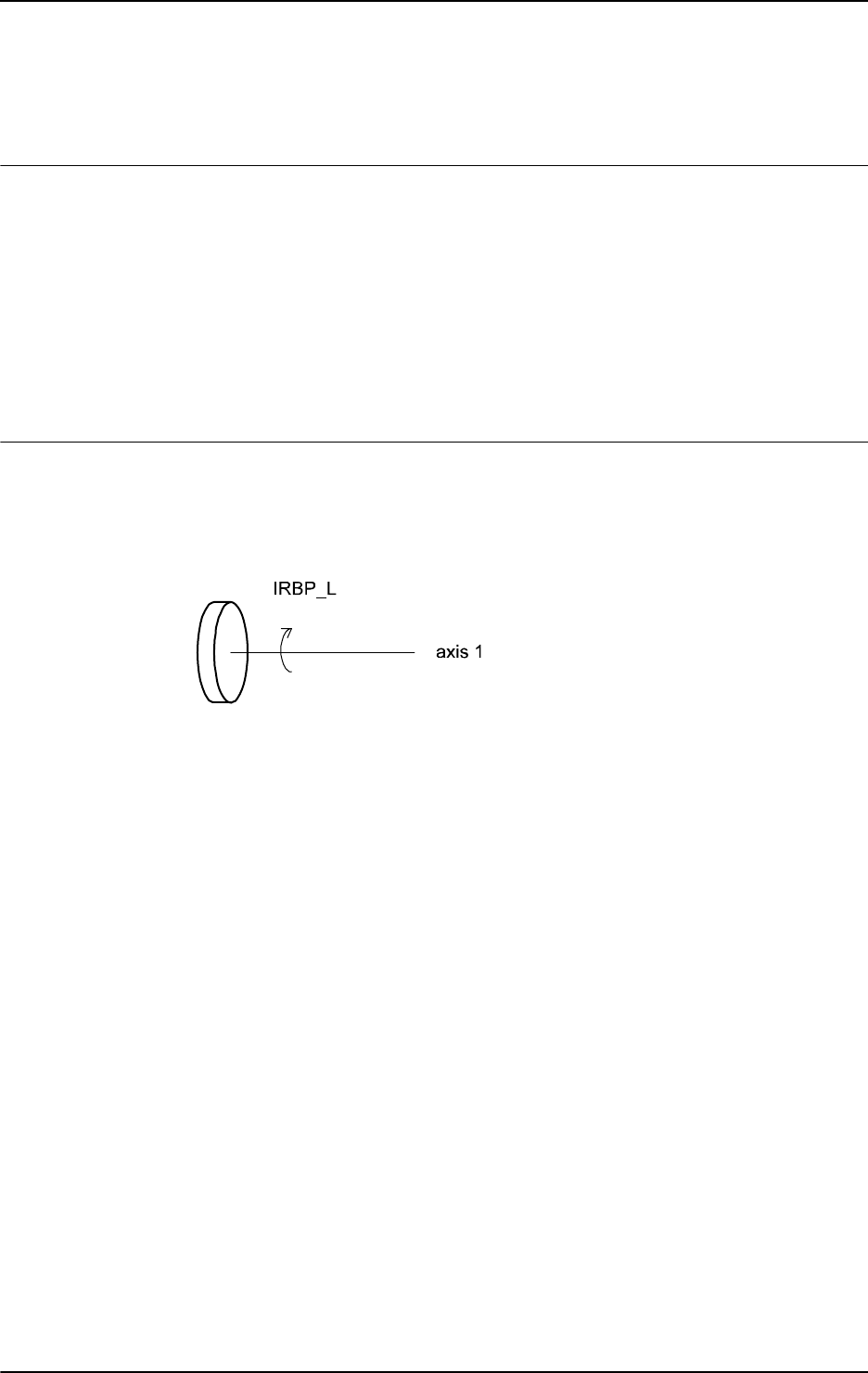
1 Instructions
1.88. MechUnitLoad - Defines a payload for a mechanical unit
RobotWare - OS
2233HAC 16581-1 Revision: J
© Copyright 2004-2010 ABB. All rights reserved.
1.88. MechUnitLoad - Defines a payload for a mechanical unit
Usage
MechUnitLoad is used to define a payload for an external mechanical unit. (The payload for
the robot is defined with instruction
GripLoad.)
This instruction should be used for all mechanical units with dynamic model in servo to
achieve the best motion performance.
The
MechUnitLoad instruction should always be executed after execution of the instruction
ActUnit.
This instruction can only be used in the main task
T_ROB1 or, if in a MultiMove system, in
Motion tasks.
Basic examples
Basic examples of the instruction
MechUnitLoad are illustrated below.
Illustration
The following figure shows a mechanical unit named IRBP_L of type IRBP L.
xx0500002142
Example 1
ActUnit IRBP_L;
MechUnitLoad IRBP_L, 1, load0;
Activate mechanical unit IRBP_L and define the payload load0 corresponding to no load (at
all) mounted on axis
1.
Example 2
ActUnit IRBP_L;
MechUnitLoad IRBP_L, 1, fixture1;
Activate mechanical unit IRBP_L and define the payload fixture1 corresponding to fixture
fixture1 mounted on axis 1.
Example 3
ActUnit IRBP_L;
MechUnitLoad IRBP_L, 1, workpiece1;
Activate mechanical unit IRBP_L and define the payload workpiece1 corresponding to
fixture and work piece named
workpiece1 mounted on axis 1.
Continues on next page
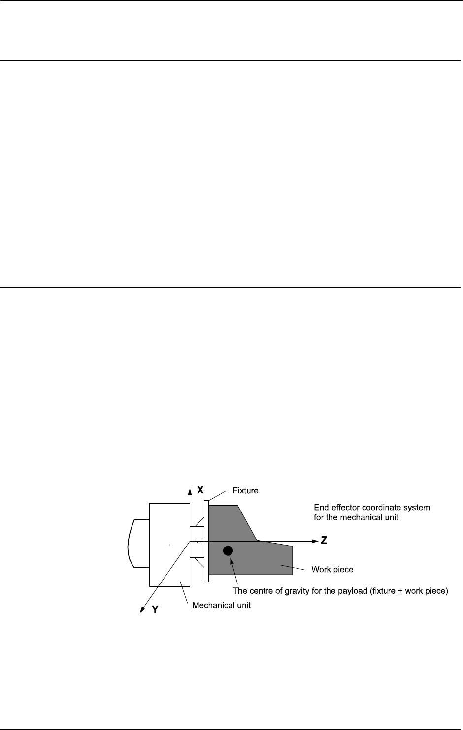
1 Instructions
1.88. MechUnitLoad - Defines a payload for a mechanical unit
RobotWare - OS
3HAC 16581-1 Revision: J224
© Copyright 2004-2010 ABB. All rights reserved.
Arguments
MechUnitLoad MechUnit AxisNo Load
MechUnit
Mechanical Unit
Data type:
mecunit
The name of the mechanical unit.
AxisNo
Axis Number
Data type:
num
The axis number within the mechanical unit that holds the load.
Load
Data type: loaddata
The load data that describes the current payload to be defined.
Program execution
After execution of
MechUnitLoad, when the robot and external axes have come to a
standstill, the specified load is defined for the specified mechanical unit and axis. This means
that the payload is controlled and monitored by the control system.
The default payload at cold start-up, for a certain mechanical unit type, is the predefined
maximal payload for this mechanical unit type.
When some other payload is used the actual payload for the mechanical unit and axis should
be redefined with this instruction. This should always be done after activation of the
mechanical unit.
The defined payload will survive a power failure restart. The defined payload will also
survive a restart of the program after manual activation of some other mechanical units from
the jogging window.
The following figure shows a payload mounted on the end-effector of a mechanical unit.
xx0500002143
Continued
Continues on next page
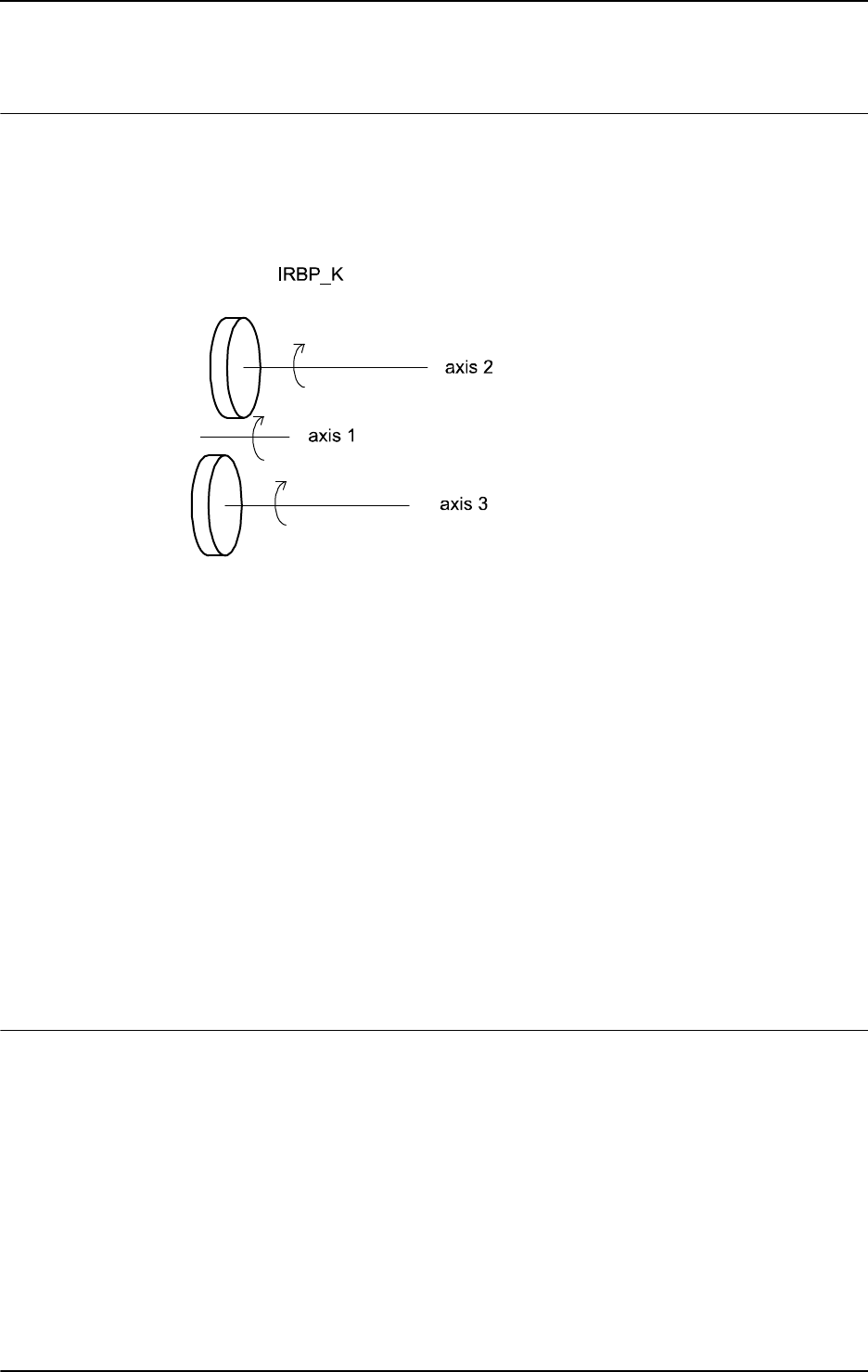
1 Instructions
1.88. MechUnitLoad - Defines a payload for a mechanical unit
RobotWare - OS
2253HAC 16581-1 Revision: J
© Copyright 2004-2010 ABB. All rights reserved.
More examples
More examples of how to use the instruction
MechUnitLoad are illustrated below.
Illustration
The following figure shows a mechanical unit named IRBP_K of type IRBP K with three
axes.
xx0500002144
Example 1
MoveL homeside1, v1000, fine, gun1;
...
ActUnit IRBP_K;
The whole mechanical unit IRBP_K is activated.
Example 2
MechUnitLoad IRBP_K, 2, workpiece1;
Defines payload workpiece1 on the mechanical unit IRBP_K axis 2.
Example 3
MechUnitLoad IRBP_K, 3, workpiece2;
Defines payload workpiece2 on the mechanical unit IRBP_K axis 3.
Example 4
MoveL homeside2, v1000, fine, gun1;
The axes of the mechanical unit IRBP_K move to the switch position homeside2 with
mounted payload on both axes
2 and 3.
Limitations
If this instruction is preceded by a move instruction, that move instruction must be
programmed with a stop point (zonedata
fine), not a fly-by point. Otherwise restart after
power failure will not be possible.
MechUnitLoad cannot be executed in a RAPID routine connected to any of the following
special system events: PowerOn, Stop, QStop, Restart or Step.
Continued
Continues on next page

1 Instructions
1.88. MechUnitLoad - Defines a payload for a mechanical unit
RobotWare - OS
3HAC 16581-1 Revision: J226
© Copyright 2004-2010 ABB. All rights reserved.
Syntax
MechUnitLoad
[MechUnit ’:=’ ] <variable (VAR) of mecunit>’ ,’
[AxisNo ´:=’ ] <expression (IN) of num> ´,’
[Load ’:=’ ] <persistent (PERS) of loaddata>’;’
Related information
For information about See
Identification of payload for external
mechanical units
Application manual - Additional axes and stand
alone controller
Mechanical units mecunit - Mechanical unit on page 1139
Definition of load data loaddata - Load data on page 1132
Definition of payload for the robot GripLoad - Defines the payload for the robot on
page 119
Continued

1 Instructions
1.89. MotionSup - Deactivates/Activates motion supervision
Collision Detection
2273HAC 16581-1 Revision: J
© Copyright 2004-2010 ABB. All rights reserved.
1.89. MotionSup - Deactivates/Activates motion supervision
Usage
MotionSup (Motion Supervision) is used to deactivate or activate the motion supervision
function for robot movements during program execution.
This instruction can only be used in the main task
T_ROB1 or, if in a MultiMove system, in
Motion tasks.
Description
Motion supervision is the name of a collection of functions for high sensitivity, model-based
supervision of the robot. Currently it contains functionality for load supervision, jam
supervision, and collision detection. Because the supervision is designed to be very sensitive
it may trip if there are large process forces acting on the robot.
If the load is not correctly defined use the load identification function to specify it. If large
external process forces are present in most parts of the application, such as during deburring,
then use the system parameters to raise the supervision level of the motion supervision until
it no longer triggers. If, however, the external forces are only temporary, such as during the
closing of a large spotweld gun, then the
MotionSup instruction should be used to raise the
supervision level (or turn the function off) for those parts of the application where the
disturbance acts.
Basic examples
Basic examples of the instruction
MotionSup are illustrated below.
Example 1
! If the motion supervision is active in the system parameters,
! then it is active by default during program execution
...
! If the motion supervision is deactivated through the system
! parameters,
! then it cannot be activated through the MotionSup instruction
...
! Deactivate motion supervision during program execution
MotionSup \Off;
...
! Activate motion supervision again during program execution
MotionSup \On;
...
! Tune the supervision level to 200% (makes the function less
! sensitive) of the level in
! the system parameters
MotionSup \On \TuneValue:= 200;
...
Continues on next page

1 Instructions
1.89. MotionSup - Deactivates/Activates motion supervision
Collision Detection
3HAC 16581-1 Revision: J228
© Copyright 2004-2010 ABB. All rights reserved.
Arguments
MotionSup[\On] | [\Off] [\TuneValue]
[ \On ]
Data type: switch
Activate the motion supervision function during program execution (if it has already been
activated in system parameters).
[ \Off ]
Data type: switch
Deactivate the motion supervision function during program execution.
One of the arguments
\On or \Off must be specified.
[ \TuneValue ]
Data type: num
Tuning the motion supervision sensitivity level in percent (1 - 300%) of system parameter
level. A higher level gives more robust sensitivity. This argument can only be combined with
argument
\On.
Program execution
If the function motion supervision is active both in the system parameters and in the RAPID
program and the motion supervision is triggered because of a collision etc., then
• the robot will stop as quickly as possible
• the robot will back up to remove any residual forces
• the program execution will stop with an error message
If motion supervision is active in system parameters it is then active by default during
program execution (
TuneValue 100%). These values are set automatically
• at a cold start-up.
• when a new program is loaded.
• when starting program execution from the beginning.
Limitations
Motion supervision is never active for external axes or when one or more joints are run in
independent joint mode. When using the robot in the soft servo mode it may be necessary to
turn the motion supervision off to avoid accidental tripping.
Syntax
MotionSup
[ ’\’ On] | [ ’\’ Off ]
[’\’ Tunevalue’:=’< expression (IN) of num> ] ’;´
Continued
Continues on next page

1 Instructions
1.89. MotionSup - Deactivates/Activates motion supervision
Collision Detection
2293HAC 16581-1 Revision: J
© Copyright 2004-2010 ABB. All rights reserved.
Related information
For information about See
General description of the function Technical reference manual - RAPID overview,
section Motion and I/O principles - Motion
supervision/collision detection
Tuning using system parameters Technical reference manual - System parameters,
section Motion - Motion Planner - Use Motion
Supervision
Continued

1 Instructions
1.90. MoveAbsJ - Moves the robot to an absolute joint position
RobotWare - OS
3HAC 16581-1 Revision: J230
© Copyright 2004-2010 ABB. All rights reserved.
1.90. MoveAbsJ - Moves the robot to an absolute joint position
Usage
MoveAbsJ (Move Absolute Joint) is used to move the robot and external axes to an absolute
position defined in axes positions.
Examples of use:
• the end point is a singular point
• for ambiguous positions on the IRB 6400C, e.g. for movements with the tool over the
robot
The final position of the robot during a movement with
MoveAbsJ is neither affected by the
given tool and work object nor by active program displacement. However, the robot uses this
data to calculate the load, TCP velocity, and the corner path. The same tools can be used in
adjacent movement instructions.
The robot and external axes move to the destination position along a non-linear path. All axes
reach the destination position at the same time.
This instruction can only be used in the main task
T_ROB1 or, if in a MultiMove system, in
Motion tasks.
Basic examples
Basic examples of the instruction
MoveAbsJ are illustrated below.
See also More examples on page 233.
Example 1
MoveAbsJ p50, v1000, z50, tool2;
The robot with the tool tool2 is moved along a non-linear path to the absolute axis position,
p50, with velocity data v1000 and zone data z50.
Example 2
MoveAbsJ *, v1000\T:=5, fine, grip3;
The robot with the tool grip3 is moved along a non-linear path to a stop point which is stored
as an absolute axis position in the instruction (marked with an *). The entire movement takes
5 seconds.
Continues on next page

1 Instructions
1.90. MoveAbsJ - Moves the robot to an absolute joint position
RobotWare - OS
2313HAC 16581-1 Revision: J
© Copyright 2004-2010 ABB. All rights reserved.
Arguments
MoveAbsJ [\Conc] ToJointPos [\ID] [\NoEOffs] Speed [\V] | [\T]
Zone [\Z] [\Inpos] Tool [\WObj]
[\Conc]
Concurrent
Data type:
switch
Subsequent instructions are executed while the robot is moving. The argument is usually not
used but is used to shorten the cycle time when, for example, communicating with external
equipment if synchronization is not required.
Using the argument
\Conc, the number of movement instructions in succession is limited to
5. In a program section that includes
StorePath-RestoPath movement instructions with
the argument
\Conc are not permitted.
If this argument is omitted and the
ToJointPos is not a stop point, the subsequent instruction
is executed some time before the robot has reached the programmed zone.
This argument can not be used in coordinated synchronized movement in a MultiMove
System.
ToJointPos
To Joint Position
Data type:
jointtarget
The destination absolute joint position of the robot and external axes. It is defined as a named
position or stored directly in the instruction (marked with an * in the instruction).
[ \ID ]
Synchronization id
Data type:
identno
This argument must be used in a MultiMove System, if it is a coordinated synchronized
movement, and is not allowed in any other cases.
The specified id number must be the same in all cooperating program tasks. The id number
gives a guarantee that the movements are not mixed up at runtime.
[ \NoEOffs ]
No External Offsets
Data type:
switch
If the argument \NoEOffs is set then the movement with MoveAbsJ is not affected by active
offsets for external axes.
Speed
Data type: speeddata
The speed data that applies to movements. Speed data defines the velocity of the tool center
point, the tool reorientation, and external axes.
Continued
Continues on next page

1 Instructions
1.90. MoveAbsJ - Moves the robot to an absolute joint position
RobotWare - OS
3HAC 16581-1 Revision: J232
© Copyright 2004-2010 ABB. All rights reserved.
[ \V ]
Vel oc it y
Data type:
num
This argument is used to specify the velocity of the TCP in mm/s directly in the instruction.
It is then substituted for the corresponding velocity specified in the speed data.
[ \T ]
Time
Data type:
num
This argument is used to specify the total time in seconds during which the robot moves. It is
then substituted for the corresponding speed data.
Zone
Data type: zonedata
Zone data for the movement. Zone data describes the size of the generated corner path.
[ \Z ]
Zone
Data type: num
This argument is used to specify the position accuracy of the robot TCP directly in the
instruction. The length of the corner path is given in mm, which is substituted for the
corresponding zone that is specified in the zone data.
[ \Inpos ]
In position
Data type:
stoppointdata
This argument is used to specify the convergence criteria for the position of the robots TCP
in the stop point. The stop point data substitutes the zone specified in the
Zone parameter.
Tool
Data type: tooldata
The tool in use during the movement.
The position of the TCP and the load on the tool are defined in the tool data. The TCP position
is used to calculate the velocity and the corner path for the movement.
[ \WObj ]
Work Object
Data type:
wobjdata
The work object used during the movement.
This argument can be omitted if the tool is held by the robot. However, if the robot holds the
work object, i.e. the tool is stationary, or with coordinated external axes, then the argument
must be specified.
In the case of a stationary tool or coordinated external axes, the data used by the system to
calculate the velocity and the corner path for the movement is defined in the work object.
Continued
Continues on next page

1 Instructions
1.90. MoveAbsJ - Moves the robot to an absolute joint position
RobotWare - OS
2333HAC 16581-1 Revision: J
© Copyright 2004-2010 ABB. All rights reserved.
Program execution
A movement with
MoveAbsJ is not affected by active program displacement and if executed
with switch \
NoEOffs there will be no offset for external axes. Without switch \NoEOffs the
external axes in the destination target are affected by active offset for external axes.
The tool is moved to the destination absolute joint position with interpolation of the axis
angles. This means that each axis is moved with constant axis velocity and that all axes reach
the destination joint position at the same time, which results in a non-linear path.
Generally speaking, the TCP is moved at approximate programmed velocity. The tool is
reoriented and the external axes are moved at the same time as the TCP moves. If the
programmed velocity for reorientation or for the external axes cannot be attained, the velocity
of the TCP will be reduced.
A corner path is usually generated when movement is transferred to the next section of the
path. If a stop point is specified in the zone data program execution only continues when the
robot and external axes have reached the appropriate joint position.
More examples
More examples of how to use the instruction
MoveAbsJ are illustrated below.
Example 1
MoveAbsJ *, v2000\V:=2200, z40 \Z:=45, grip3;
The tool, grip3, is moved along a non-linear path to an absolute joint position stored in the
instruction. The movement is carried out with data set to
v2000 and z40. The velocity and
zone size of the TCP are
2200 mm/s and 45 mm respectively.
Example 2
MoveAbsJ p5, v2000, fine \Inpos := inpos50, grip3;
The tool, grip3, is moved along a non-linear path to an absolute joint position p5. The robot
considers it to be in the point when 50% of the position condition and 50% of the speed
condition for a stop point
fine are satisfied. It waits at most for 2 seconds for the conditions
to be satisfied. See predefined data
inpos50 of data type stoppointdata.
Example 3
MoveAbsJ \Conc, *, v2000, z40, grip3;
The tool, grip3, is moved along a non-linear path to an absolute joint position stored in the
instruction. Subsequent logical instructions are executed while the robot moves.
Example 4
MoveAbsJ \Conc, * \NoEOffs, v2000, z40, grip3;
Same movement as above but the movement is not affected by active offsets for external axes.
Example 5
GripLoad obj_mass;
MoveAbsJ start, v2000, z40, grip3 \WObj:= obj;
The robot moves the work object obj in relation to the fixed tool grip3 along a non-linear
path to an absolute axis position
start.
Continued
Continues on next page
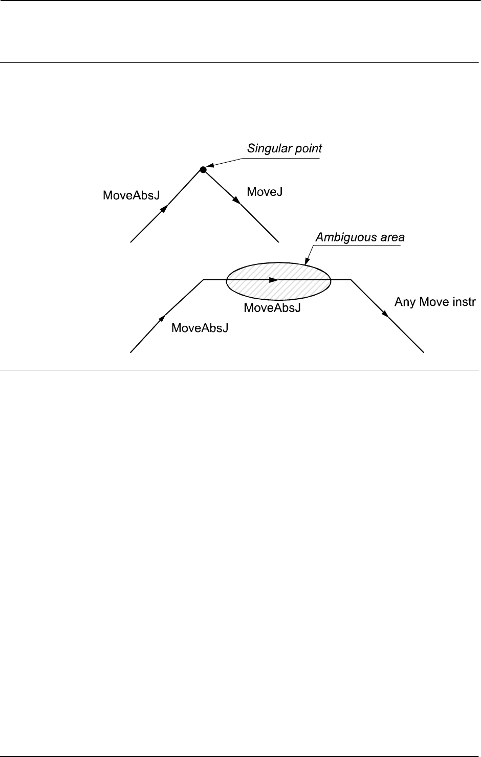
1 Instructions
1.90. MoveAbsJ - Moves the robot to an absolute joint position
RobotWare - OS
3HAC 16581-1 Revision: J234
© Copyright 2004-2010 ABB. All rights reserved.
Limitations
In order to be able to run backwards with the instruction
MoveAbsJ involved and avoiding
problems with singular points or ambiguous areas, it is essential that the subsequent
instructions fulfil certain requirements as follows (see figure below).
The figure shows limitation for backward execution with
MoveAbsJ.
xx0500002201
Syntax
MoveAbsJ
[ ’\’ Conc ’,’ ]
[ ToJointPos’ :=’ ] < expression (IN) of jointtarget >
[ ’\’ ID ’:=’ < expression (IN) of identno >]
[ ’\’ NoEoffs ] ’,’
[ Speed ’:=’ ] < expression (IN) of speeddata >
[ ’\’ V ’:=’ < expression (IN) of num > ]
| [ ’\’ T’ :=’ < expression (IN) of num > ] ’,’
[Zone ’:=’ ] < expression (IN) of zonedata>
[’\’ Z ´:=’ ] < expression (IN) of num >
[ ’\’ Inpos’ :=’ < expression (IN) of stoppointdata > ] ´,’
[ Tool ’:=’ ] < persistent (PERS) of tooldata >
[ ’\’ WObj’ :=’ < persistent (PERS) of wobjdata > ] ’;’
.
Continued
Continues on next page

1 Instructions
1.90. MoveAbsJ - Moves the robot to an absolute joint position
RobotWare - OS
2353HAC 16581-1 Revision: J
© Copyright 2004-2010 ABB. All rights reserved.
Related information
For information about See
Other positioning instructions Technical reference manual - RAPID overview,
section RAPID summary - Motion
Definition of jointtarget jointtarget - Joint position data on page 1129
Definition of velocity speeddata - Speed data on page 1185
Definition of zone data zonedata - Zone data on page 1232
Definition of stop point data stoppointdata - Stop point data on page 1189
Definition of tools tooldata - Tool data on page 1207
Definition of work objects wobjdata - Work object data on page 1224
Motion in general Technical reference manual - RAPID overview,
section Motion and I/O principles
Concurrent program execution Technical reference manual - RAPID overview,
section Motion and I/O principles - Synchronization
with logical instructions
Continued
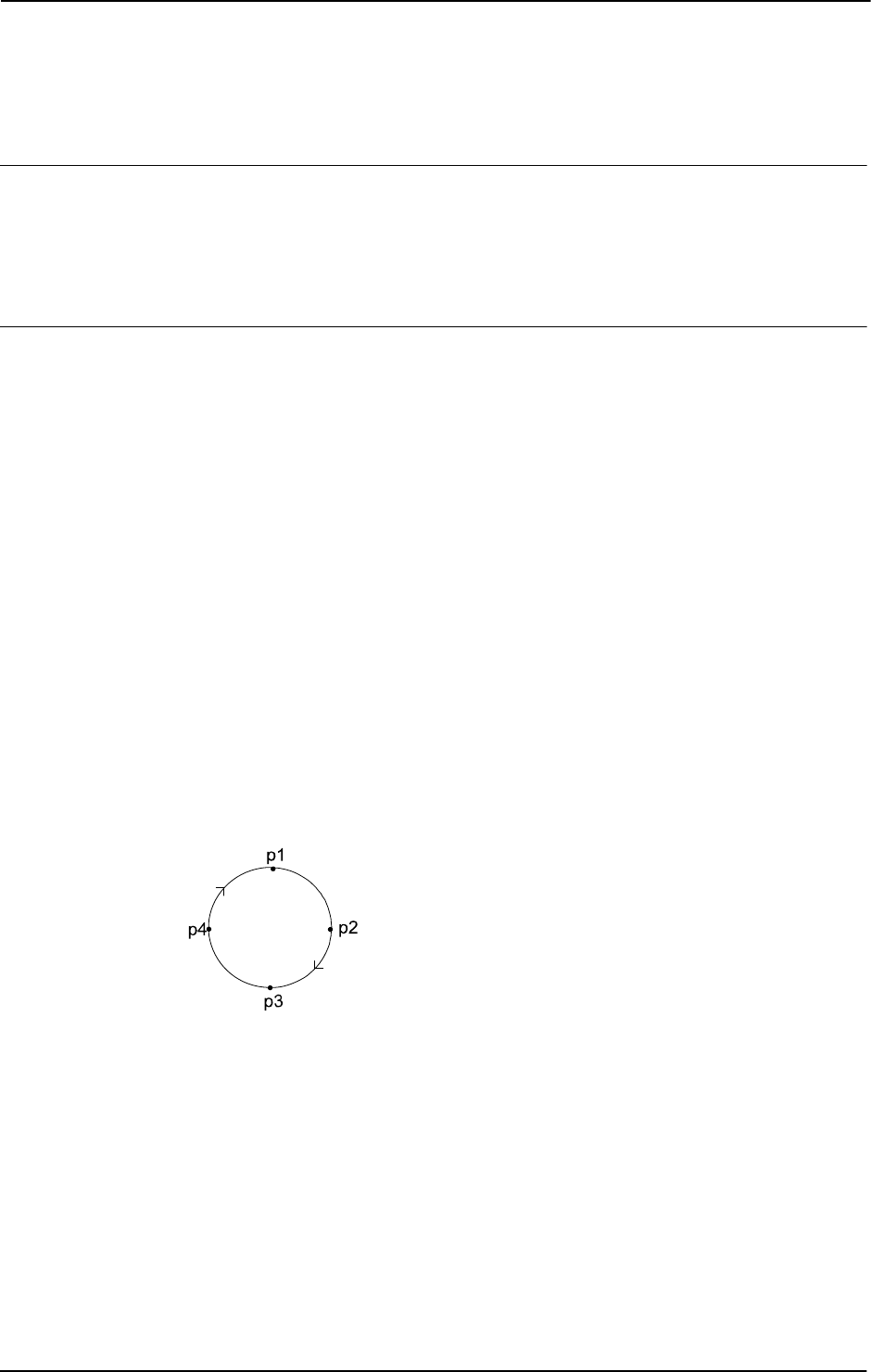
1 Instructions
1.91. MoveC - Moves the robot circularly
RobotWare - OS
3HAC 16581-1 Revision: J236
© Copyright 2004-2010 ABB. All rights reserved.
1.91. MoveC - Moves the robot circularly
Usage
MoveC is used to move the tool center point (TCP) circularly to a given destination. During
the movement the orientation normally remains unchanged relative to the circle.
This instruction can only be used in the main task
T_ROB1 or, if in a MultiMove system, in
Motion tasks.
Basic examples
Basic examples of the instruction
MoveC are illustrated below.
See also More examples on page 239.
Example 1
MoveC p1, p2, v500, z30, tool2;
The TCP of the tool, tool2, is moved circularly to the position p2 with speed data v500 and
zone data
z30. The circle is defined from the start position, the circle point p1, and the
destination point
p2.
Example 2
MoveC *, *, v500 \T:=5, fine, grip3;
The TCP of the tool, grip3, is moved circularly to a fine point stored in the instruction
(marked by the second *). The circle point is also stored in the instruction (marked by the first
*). The complete movement takes
5 seconds.
Example 3
MoveL p1, v500, fine, tool1;
MoveC p2, p3, v500, z20, tool1;
MoveC p4, p1, v500, fine, tool1;
The figure shows how a complete circle is performed by two MoveC instructions.
xx0500002212
Continues on next page

1 Instructions
1.91. MoveC - Moves the robot circularly
RobotWare - OS
2373HAC 16581-1 Revision: J
© Copyright 2004-2010 ABB. All rights reserved.
Arguments
MoveC [\Conc] CirPoint ToPoint [\ID] Speed [\V] | [\T] Zone [\Z]
[\Inpos] Tool [\WObj] [\Corr]
[ \Conc ]
Concurrent
Data type:
switch
Subsequent instructions are executed while the robot is moving. The argument is usually not
used but can be used to avoid unwanted stops caused by overloaded CPU when using fly-by
points. This is useful when the programmed points are very close together at high speeds. The
argument is also useful when, for example, communicating with external equipment and
synchronization between the external equipment and robot movement is not required.
Using the argument
\Conc, the number of movement instructions in succession is limited to
5. In a program section that includes
StorePath-RestoPath, movement instructions with
the argument
\Conc are not permitted.
If this argument is omitted and the
ToPoint is not a stop point then the subsequent instruction
is executed some time before the robot has reached the programmed zone.
This argument can not be used in coordinated synchronized movement in a MultiMove
System.
CirPoint
Data type: robtarget
The circle point of the robot. The circle point is a position on the circle between the start point
and the destination point. To obtain the best accuracy it should be placed about halfway
between the start and destination points. If it is placed too close to the start or destination
point, the robot may give a warning. The circle point is defined as a named position or stored
directly in the instruction (marked with an * in the instruction). The position of the external
axes are not used.
ToPoint
Data type: robtarget
The destination point of the robot and external axes. It is defined as a named position or stored
directly in the instruction (marked with an * in the instruction).
[ \ID ]
Synchronization id
Data type:
identno
This argument must be used in a MultiMove System, if it is a coordinated synchronized
movement, and is not allowed in any other cases.
The specified id number must be the same in all cooperating program tasks. The id number
gives a guarantee that the movements are not mixed up at runtime.
Speed
Data type: speeddata
The speed data that applies to movements. Speed data defines the velocity of the TCP, the tool
reorientation, and external axes.
Continued
Continues on next page

1 Instructions
1.91. MoveC - Moves the robot circularly
RobotWare - OS
3HAC 16581-1 Revision: J238
© Copyright 2004-2010 ABB. All rights reserved.
[ \V ]
Vel oc it y
Data type:
num
This argument is used to specify the velocity of the TCP in mm/s directly in the instruction.
It is then substituted for the corresponding velocity specified in the speed data.
[ \T ]
Time
Data type:
num
This argument is used to specify the total time in seconds during which the robot and external
axes move. It is then substituted for the corresponding speed data.
Zone
Data type: zonedata
Zone data for the movement. Zone data describes the size of the generated corner path.
[ \Z ]
Zone
Data type:
num
This argument is used to specify the position accuracy of the robot TCP directly in the
instruction. The length of the corner path is given in mm, which is substituted for the
corresponding zone specified in the zone data.
[ \Inpos ]
In position
Data type:
stoppointdata
This argument is used to specify the convergence criteria for the position of the robot’s TCP
in the stop point. The stop point data substitutes the zone specified in the
Zone parameter.
Tool
Data type: tooldata
The tool in use when the robot moves. The tool center point is the point that is moved to the
specified destination point.
[ \WObj ]
Work Object
Data type:
wobjdata
The work object (object coordinate system) to which the robot position in the instruction is
related.
This argument can be omitted and if it is then the position is related to the world coordinate
system. If, on the other hand, a stationary TCP or coordinated external axes are used this
argument must be specified in order for a circle relative to the work object to be executed.
[ \Corr ]
Correction
Data type:
switch
Correction data written to a corrections entry by the instruction CorrWrite will be added to
the path and destination position if this argument is present.
Continued
Continues on next page
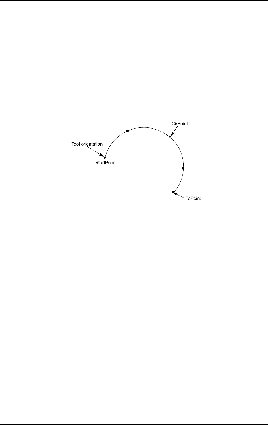
1 Instructions
1.91. MoveC - Moves the robot circularly
RobotWare - OS
2393HAC 16581-1 Revision: J
© Copyright 2004-2010 ABB. All rights reserved.
Program execution
The robot and external units are moved to the destination point as follows:
• The TCP of the tool is moved circularly at a constant programmed velocity.
• The tool is reoriented at a constant velocity from the orientation at the start position to
the orientation at the destination point.
• The reorientation is performed relative to the circular path. Thus, if the orientation
relative to the path is the same at the start and the destination points, the relative
orientation remains unchanged during the movement (see figure below).
The figure shows tool orientation during circular movement.
xx0500002214
The orientation in the circle point is not reached. It is only used to distinguish between two
possible directions of reorientation. The accuracy of the reorientation along the path depends
only on the orientation at the start and destination points.
Different modes for tool orientation during circle path are described in instruction
CirPathMode.
Uncoordinated external axes are executed at constant velocity in order for them to arrive at
the destination point at the same time as the robot axes. The position in the circle position is
not used.
If it is not possible to attain the programmed velocity for the reorientation or for the external
axes, the velocity of the TCP will be reduced.
A corner path is usually generated when movement is transferred to the next section of a path.
If a stop point is specified in the zone data, program execution only continues when the robot
and external axes have reached the appropriate position.
More examples
More examples of how to use the instruction
MoveC are illustrated below.
Example 1
MoveC *, *, v500 \V:=550, z40 \Z:=45, grip3;
The TCP of the tool, grip3, is moved circularly to a position stored in the instruction. The
movement is carried out with data set to
v500 and z40; the velocity and zone size of the TCP
are
550 mm/s and 45 mm respectively.
Continued
Continues on next page
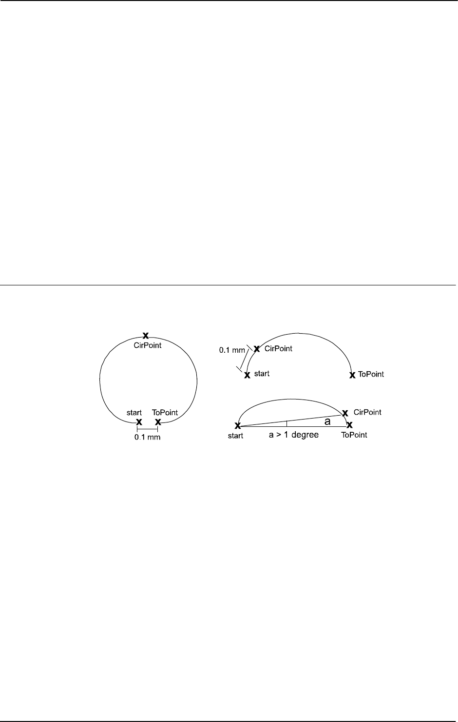
1 Instructions
1.91. MoveC - Moves the robot circularly
RobotWare - OS
3HAC 16581-1 Revision: J240
© Copyright 2004-2010 ABB. All rights reserved.
Example 2
MoveC p5, p6, v2000, fine \Inpos := inpos50, grip3;
The TCP of the tool, grip3, is moved circularly to a stop point p6. The robot considers it to
be in the point when 50% of the position condition and 50% of the speed condition for a stop
point
fine are satisfied. It waits at most for 2 seconds for the conditions to be satisfied. See
predefined data
inpos50 of data type stoppointdata.
Example 3
MoveC \Conc, *, *, v500, z40, grip3;
The TCP of the tool, grip3, is moved circularly to a position stored in the instruction. The
circle point is also stored in the instruction. Subsequent logical instructions are executed
while the robot moves.
Example 4
MoveC cir1, p15, v500, z40, grip3 \WObj:=fixture;
The TCP of the tool, grip3, is moved circularly to a position, p15 via the circle point cir1.
These positions are specified in the object coordinate system for
fixture.
Limitations
There are some limitations in how the
CirPoint and the ToPoint can be placed, as shown
in the figure below.
xx0500002213
• Minimum distance between start and ToPoint is 0.1 mm
• Minimum distance between start and CirPoint is 0.1 mm
• Minimum angle between CirPoint and ToPoint from the start point is 1 degree
The accuracy can be poor near the limits, e.g. if the start point and the
ToPoint on the circle
are close to each other then the fault caused by the leaning of the circle can be much greater
than the accuracy with which the points have been programmed.
Make sure that the robot can reach the circle point during program execution and divide the
circle segment if necessary.
A change of execution mode from forward to backward or vice versa while the robot is
stopped on a circular path is not permitted and will result in an error message.
Continued
Continues on next page

1 Instructions
1.91. MoveC - Moves the robot circularly
RobotWare - OS
2413HAC 16581-1 Revision: J
© Copyright 2004-2010 ABB. All rights reserved.
WARNING!
The instruction
MoveC (or any other instruction including circular movement) should never
be started from the beginning with TCP between the circle point and the end point. Otherwise
the robot will not take the programmed path (positioning around the circular path in another
direction compared with that which is programmed).
To minimize the risk set the system parameter Restrict placing of circlepoints to TRUE (type
Motion Planner, topic Motion). The parameter adds a supervision that the circle path not turns
around more than 240 degrees and that the circle point is placed in the middle part of the circle
path.
Syntax
MoveC
[ ’\’ Conc ’,’ ]
[ CirPoint’ :=’ ] < expression (IN) of robtarget> ’,’
[ ToPoint’ :=’ ] < expression (IN) of robtarget> ’,’
[ ’\’ ID ’:=’ < expression (IN) of identno>]’,’
[ Speed ’:=’ ] < expression (IN) of speeddata>
[ ’\’ V ’:=’ < expression (IN) of num> ]
[ ’\’ T ’:=’ < expression (IN) of num> ] ’,’
[Zone ’:=’ ] < expression (IN) of zonedata>
[ ’\’ Z ’:=’ < expression (IN) of num> ]
[ ’\’ Inpos’ :=’ < expression (IN) of stoppointdata> ] ´,’
[ Tool ’:=’ ] < persistent (PERS) of tooldata>
[ ’\’ WObj’ :=’ < persistent (PERS) of wobjdata> ]
[ ’\’ Corr ]’;’
Related information
For information about See
Other positioning instructions Technical reference manual - RAPID overview, section
RAPID summary - Motion
Definition of velocity speeddata - Speed data on page 1185
Definition of zone data zonedata - Zone data on page 1232
Definition of stop point data stoppointdata - Stop point data on page 1189
Definition of tools tooldata - Tool data on page 1207
Definition of work objects wobjdata - Work object data on page 1224
Writes to a corrections entry CorrWrite - Writes to a correction generator on page 77
Tool reorientation during circle
path
CirPathMode - Tool reorientation during circle path on
page 38
Motion in general Technical reference manual - RAPID overview, section
Motion and I/O principles
Coordinate systems Technical reference manual - RAPID overview, section
Motion and I/O principles - Coordinate systems
Concurrent program execution Technical reference manual - RAPID overview, section
Motion and I/O principles - Synchronization with logical
instructions
System parameters Technical reference manual - System parameters
Continued

1 Instructions
1.92. MoveCDO - Moves the robot circularly and sets digital output in the corner
RobotWare - OS
3HAC 16581-1 Revision: J242
© Copyright 2004-2010 ABB. All rights reserved.
1.92. MoveCDO - Moves the robot circularly and sets digital output in the corner
Usage
MoveCDO (Move Circular Digital Output) is used to move the tool center point (TCP)
circularly to a given destination. The specified digital output is set/reset in the middle of the
corner path at the destination point. During the movement the orientation normally remains
unchanged relative to the circle.
This instruction can only be used in the main task
T_ROB1 or, if in a MultiMove system, in
Motion tasks.
Basic examples
Basic examples of the instruction
MoveCDO are illustrated below.
Example 1
MoveCDO p1, p2, v500, z30, tool2, do1,1;
The TCP of the tool, tool2, is moved circularly to the position p2 with speed data v500 and
zone data
z30. The circle is defined from the start position, the circle point p1, and the
destination point
p2. Output do1 is set in the middle of the corner path at p2.
Arguments
MoveCDO CirPoint ToPoint [\ID] Speed [\T] Zone Tool [\WObj] Signal
Value
CirPoint
Data type: robtarget
The circle point of the robot. The circle point is a position on the circle between the start point
and the destination point. To obtain the best accuracy it should be placed about halfway
between the start and destination points. If it is placed too close to the start or destination point
the robot may give a warning. The circle point is defined as a named position or stored
directly in the instruction (marked with an * in the instruction). The position of the external
axes are not used.
ToPoint
Data type: robtarget
The destination point of the robot and external axes. It is defined as a named position or stored
directly in the instruction (marked with an * in the instruction).
[ \ID ]
Synchronization id
Data type:
identno
This argument must be used in a MultiMove System, if coordinated synchronized movement,
and is not allowed in any other cases.
The specified ID number must be the same in all cooperating program tasks. The ID number
gives a guarantee that the movements are not mixed up at runtime.
Continues on next page

1 Instructions
1.92. MoveCDO - Moves the robot circularly and sets digital output in the corner
RobotWare - OS
2433HAC 16581-1 Revision: J
© Copyright 2004-2010 ABB. All rights reserved.
Speed
Data type: speeddata
The speed data that applies to movements. Speed data defines the velocity of the TCP, the tool
reorientation, and external axes.
[ \T ]
Time
Data type:
num
This argument is used to specify the total time in seconds during which the robot and external
axes move. It is then substituted for the corresponding speed data.
Zone
Data type: zonedata
Zone data for the movement. Zone data describes the size of the generated corner path.
Tool
Data type: tooldata
The tool in use when the robot moves. The tool center point is the point that is moved to the
specified destination point.
[ \WObj ]
Work Object
Data type:
wobjdata
The work object (object coordinate system) to which the robot position in the instruction is
related.
This argument can be omitted and if so then the position is related to the world coordinate
system. If, on the other hand, a stationary TCP or coordinated external axes are used then this
argument must be specified in order for a circle relative to the work object to be executed.
Signal
Data type: signaldo
The name of the digital output signal to be changed.
Value
Data type: dionum
The desired value of signal (0 or 1).
Continued
Continues on next page
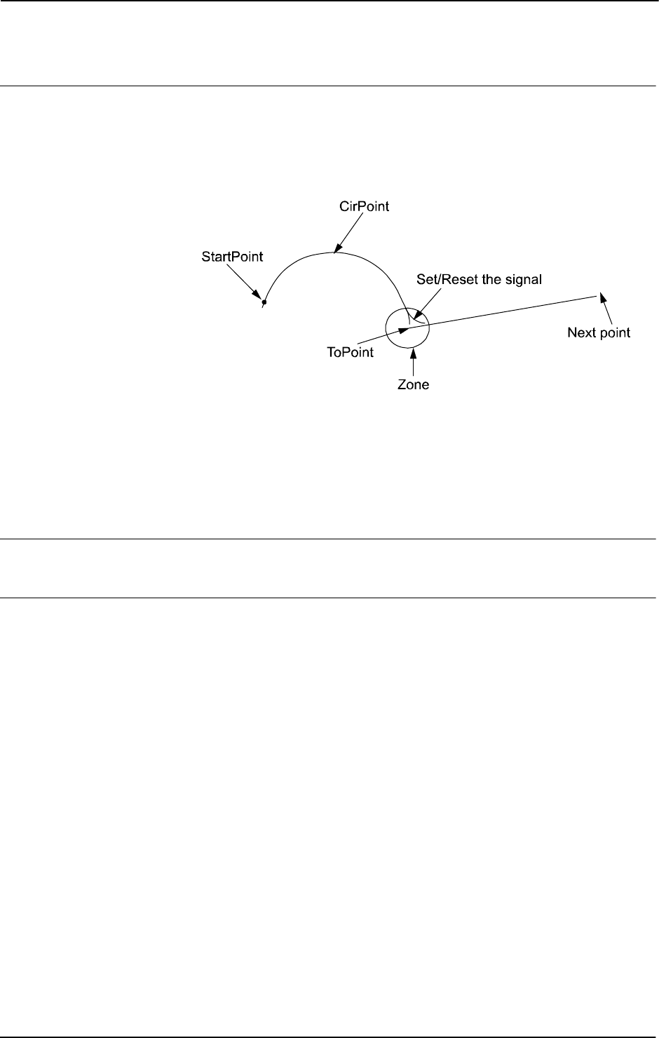
1 Instructions
1.92. MoveCDO - Moves the robot circularly and sets digital output in the corner
RobotWare - OS
3HAC 16581-1 Revision: J244
© Copyright 2004-2010 ABB. All rights reserved.
Program execution
See the instruction
MoveC for more information about circular movement.
The digital output signal is set/reset in the middle of the corner path for flying points, as
shown in figure below.
The figure shows set/reset of digital output signal in the corner path with
MoveCDO.
xx0500002215
For stop points we recommend the use of“ normal” programming sequence with MoveC +
SetDO. But when using stop point in instruction MoveCDO the digital output signal is set/reset
when the robot reaches the stop point.
The specified I/O signal is set/reset in execution mode continuously and stepwise forward,
but not in stepwise backward.
Limitations
General limitations according to instruction
MoveC.
Syntax
MoveCDO
[ CirPoint ’:=’ ] < expression (IN) of robtarget > ’,’
[ ToPoint’ :=’ ] < expression (IN) of robtarget > ’,’
[ ’\’ ID ’:=’ < expression (IN) of identno >]’,’
[ Speed ’:=’ ] < expression (IN) of speeddata >
[ ’\’ T ’:=’ < expression (IN) of num > ] ’,’
[ Zone ’:=’ ] < expression (IN) of zonedata > ’,’
[ Tool ’:=’ ] < persistent (PERS) of tooldata >
[ ’\’ WObj’ :=’ < persistent (PERS) of wobjdata > ] ’,’
[ Signal ’:=’ ] < variable (VAR) of signaldo > ] ´,’
[ Value ´:=’ ] < expression (IN) of dionum > ] ’;’
Continued
Continues on next page

1 Instructions
1.92. MoveCDO - Moves the robot circularly and sets digital output in the corner
RobotWare - OS
2453HAC 16581-1 Revision: J
© Copyright 2004-2010 ABB. All rights reserved.
Related information
For information about See
Other positioning instructions Technical reference manual - RAPID overview,
section RAPID summary - Motion
Move the robot circularly MoveC - Moves the robot circularly on page 236
Definition of velocity speeddata - Speed data on page 1185
Definition of zone data zonedata - Zone data on page 1232
Definition of tools tooldata - Tool data on page 1207
Definition of work objects wobjdata - Work object data on page 1224
Motion in general Technical reference manual - RAPID overview,
section Motion and I/O principles
Coordinate systems Technical reference manual - RAPID overview,
section Motion and I/O principles - Coordinate
systems
Movements with I/O settings Technical reference manual - RAPID overview,
section Motion and I/O principles - Synchronization
with logical instructions
Continued

1 Instructions
1.93. MoveCSync - Moves the robot circularly and executes a RAPID procedure
RobotWare - OS
3HAC 16581-1 Revision: J246
© Copyright 2004-2010 ABB. All rights reserved.
1.93. MoveCSync - Moves the robot circularly and executes a RAPID procedure
Usage
MoveCSync (Move Circular Synchronously) is used to move the tool center point (TCP)
circularly to a given destination. The specified RAPID procedure is ordered to execute at the
middle of the corner path in the destination point. During the movement the orientation
normally remains unchanged relative to the circle.
This instruction can only be used in the main task
T_ROB1 or, if in a MultiMove system, in
Motion tasks.
Basic examples
Basic examples of the instruction
MoveCSync are illustrated below.
Example 1
MoveCSync p1, p2, v500, z30, tool2, "proc1";
The TCP of the tool, tool2, is moved circularly to the position p2 with speed data v500 and
zone data
z30. The circle is defined from the start position, the circle point p1, and the
destination point
p2. Procedure proc1 is executed in the middle of the corner path at p2.
Example 2
MoveCSync p1, p2, v500, z30, tool2, "MyModule:proc1";
The same as in example 1 above, but here the locally declared procedure proc1 in module
MyModule will be called in the middle of the corner path.
Arguments
MoveCSync CirPoint ToPoint [\ID] Speed [\T] Zone Tool [\WObj]
ProcName
CirPoint
Data type: robtarget
The circle point of the robot. The circle point is a position on the circle between the start point
and the destination point. To obtain the best accuracy it should be placed about halfway
between the start and destination points. If it is placed too close to the start or destination point
the robot may give a warning. The circle point is defined as a named position or stored
directly in the instruction (marked with an * in the instruction). The position of the external
axes are not used.
ToPoint
Data type: robtarget
The destination point of the robot and external axes. It is defined as a named position or stored
directly in the instruction (marked with an * in the instruction).
Continues on next page

1 Instructions
1.93. MoveCSync - Moves the robot circularly and executes a RAPID procedure
RobotWare - OS
2473HAC 16581-1 Revision: J
© Copyright 2004-2010 ABB. All rights reserved.
[ \ID ]
Synchronization id
Data type:
identno
This argument must be used in a MultiMove system, if it is a coordinated synchronized
movement, and is not allowed in any other cases.
The specified id number must be the same in all cooperating program tasks. The id number
gives a guarantee that the movements are not mixed up at runtime.
Speed
Data type: speeddata
The speed data that applies to movements. Speed data defines the velocity of the TCP, the tool
reorientation and external axes.
[ \T ]
Time
Data type:
num
This argument is used to specify the total time in seconds during which the robot and external
axes move. It is then substituted for the corresponding speed data.
Zone
Data type: zonedata
Zone data for the movement. Zone data describes the size of the generated corner path.
Tool
Data type: tooldata
The tool in use when the robot moves. The tool center point is the point that is moved to the
specified destination point.
[ \WObj ]
Work Object
Data type:
wobjdata
The work object (object coordinate system) to which the robot position in the instruction is
related.
This argument can be omitted and if so then the position is related to the world coordinate
system. If, on the other hand, a stationary TCP or coordinated external axes are used, this
argument must be specified.
ProcName
Procedure Name
Data type:
string
Name of the RAPID procedure to be executed at the middle of the corner path in the
destination point.
Continued
Continues on next page
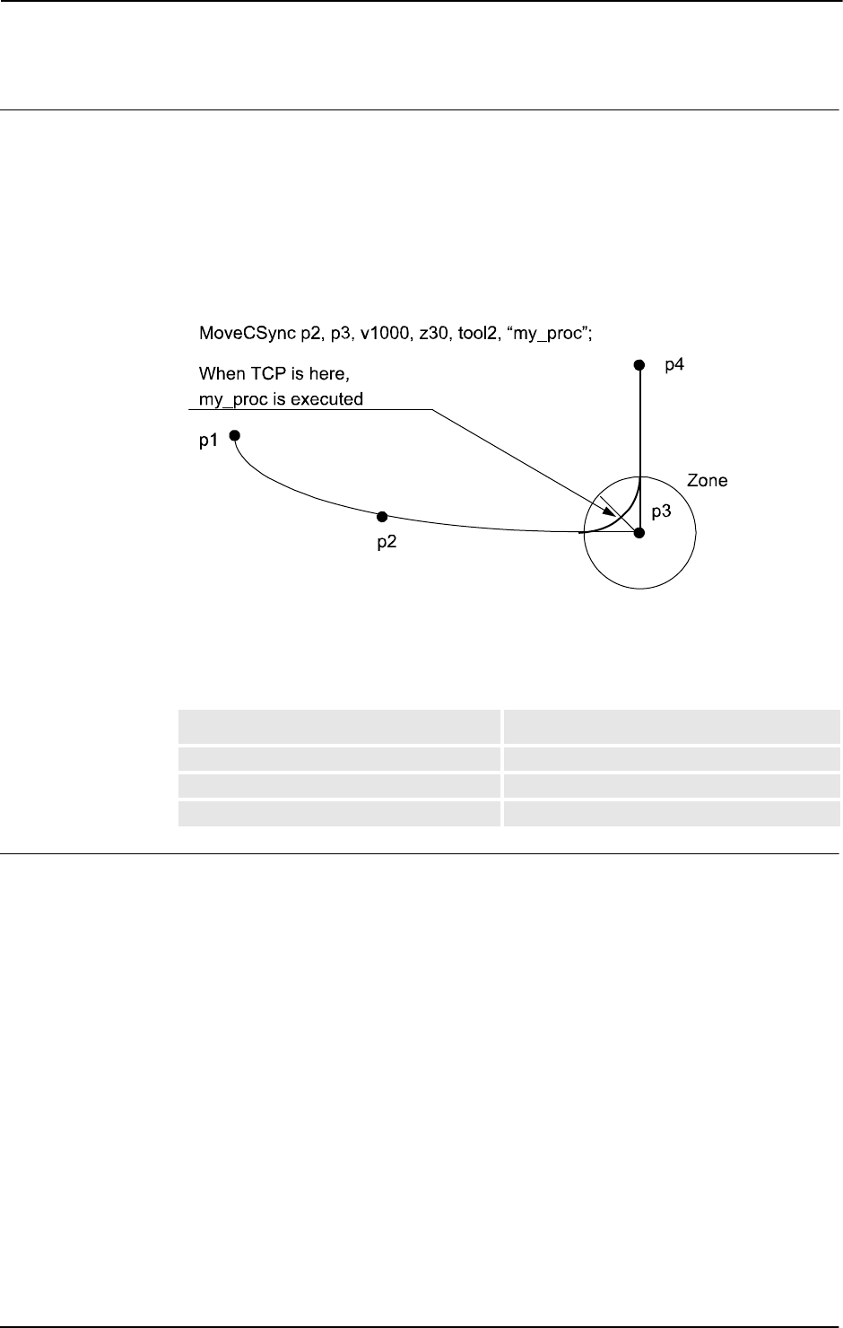
1 Instructions
1.93. MoveCSync - Moves the robot circularly and executes a RAPID procedure
RobotWare - OS
3HAC 16581-1 Revision: J248
© Copyright 2004-2010 ABB. All rights reserved.
Program execution
See the instruction
MoveC for more information about circular movements.
The specified RAPID procedure is ordered to execute when the TCP reaches the middle of
the corner path in the destination point of the
MoveCSync instruction, as shown in the figure
below.
The figure shows that the order to execute the user defined RAPID procedure is done at the
middle of the corner path.
xx0500002216
For stop points we recommend the use of“ normal” programming sequence with MoveC + and
other RAPID instructions in sequence.
The table describes execution of the specified RAPID procedure in different execution
modes:
Limitation
General limitations according to instruction
MoveC.
When the robot reaches the middle of the corner path there is normally a delay of 2-30 ms
until the specified RAPID routine is executed depending on what type of movement is being
performed at the time.
Switching execution mode after program stop from continuously or cycle to stepwise forward
or backward results in an error. This error tells the user that the mode switch can result in
missed execution of the RAPID procedure in the queue for execution on the path.
Instruction
MoveCSync cannot be used on TRAP level. The specified RAPID procedure
cannot be tested with stepwise execution.
Execution mode Execution of RAPID procedure
Continuously or Cycle According to this description
Forward step In the stop point
Backward step Not at all
Continued
Continues on next page

1 Instructions
1.93. MoveCSync - Moves the robot circularly and executes a RAPID procedure
RobotWare - OS
2493HAC 16581-1 Revision: J
© Copyright 2004-2010 ABB. All rights reserved.
Syntax
MoveCSync
[ CirPoint ’:=’ ] < expression (IN) of robtarget > ’,’
[ ToPoint’ :=’ ] < expression (IN) of robtarget > ’,’
[’\’ ID ’:=’ < expression (IN) of identno >]’,’
[ Speed ’:=’ ] < expression (IN) of speeddata >
[ ’\’ T ’:=’ < expression (IN) of num > ] ’,’
[ Zone ’:=’ ] < expression (IN) of zonedata > ’,’
[ Tool ’:=’ ] < persistent (PERS) of tooldata >
[ ’\’ WObj’ :=’ < persistent (PERS) of wobjdata > ] ’,’
[ ProcName ´:=’ ] < expression (IN) of string > ] ’;’
Related information
For information about See
Other positioning instructions Technical reference manual - RAPID overview,
section RAPID summary - Motion
Moves the robot circularly MoveC - Moves the robot circularly on page 236
Definition of velocity speeddata - Speed data on page 1185
Definition of zone data zonedata - Zone data on page 1232
Definition of tools tooldata - Tool data on page 1207
Definition of work objects wobjdata - Work object data on page 1224
Motion in general Technical reference manual - RAPID overview,
section Motion and I/O principles
Coordinate systems Technical reference manual - RAPID overview,
section Motion and I/O principles - Coordinate
systems
Defines a position related interrupt TriggInt - Defines a position related interrupt on
page 588
Continued

1 Instructions
1.94. MoveExtJ - Move one or several mechanical units without TCP
RobotWare - OS
3HAC 16581-1 Revision: J250
© Copyright 2004-2010 ABB. All rights reserved.
1.94. MoveExtJ - Move one or several mechanical units without TCP
Usage
MoveExtJ (Move External Joints) is used to move linear or rotating external axes. The
external axes can belong to one or several mechanical units without TCP.
This instruction can only be used with an actual program task defined as a Motion Task and
if the task controls one or several mechanical units without TCP.
Basic examples
Basic examples of the instruction
MoveExtJ are illustrated below.
See also More examples on page 252.
Example 1
MoveExtJ jpos10, vrot10, z50;
Move rotational external axes to joint position jpos10 with speed 10 degrees/s with zone
data
z50.
Example 2
MoveExtJ \Conc, jpos20, vrot10 \T:=5, fine \InPos:=inpos20;
Move external axes to joint position jpos20 in 5. The program execution goes forward at
once but the external axes stops in the position
jpos20 until the convergence criteria in
inpos20 are fulfilled.
Arguments
MoveExtJ [\Conc] ToJointPos [\ID] [\UseEOffs] Speed [\T] Zone
[\Inpos]
[ \Conc ]
Concurrent
Data type:
switch
Subsequent instructions are executed while the external axis is moving. The argument is
usually not used but can be used to avoid unwanted stops caused by overloaded CPU when
using fly-by points. This is useful when the programmed points are very close together at high
speeds. The argument is also useful when, for example, communicating with external
equipment and synchronization between the external equipment and robot movement is not
required.
Using the argument
\Conc, the number of movement instructions in succession is limited to
5. In a program section that includes
StorePath-RestoPath movement instructions with
the argument
\Conc are not permitted.
If this argument is omitted and the
ToJointPos is not a stop point then the subsequent
instruction is executed some time before the external axes has reached the programmed zone.
This argument can not be used in coordinated synchronized movement in a MultiMove
System.
Continues on next page

1 Instructions
1.94. MoveExtJ - Move one or several mechanical units without TCP
RobotWare - OS
2513HAC 16581-1 Revision: J
© Copyright 2004-2010 ABB. All rights reserved.
ToJointPos
To Joint Position
Data type:
jointtarget
The destination absolute joint position of the external axes. It is defined as a named position
or stored directly in the instruction (marked with an * in the instruction).
[ \ID ]
Synchronization ID
Data type:
identno
This argument must be used in a MultiMove System, if it is a coordinated synchronized
movement, and is not allowed in any other cases.
The specified ID number must be the same in all cooperating program tasks. The id number
gives a guarantee that the movements are not mixed up at runtime.
[ \UseEOffs ]
Use External Offset
Data type:
switch
The offset for external axes, setup by instruction EOffsSet, is activated for MoveExtJ
instruction when the argument
UseEOffs is used. See instruction EOffsSet for more
information about external offset.
Speed
Data type: speeddata
The speed data that applies to movements. Speed data defines the velocity of the linear or
rotating external axis.
[ \T ]
Time
Data type:
num
This argument is used to specify the total time in seconds during which the external axes
move. It is then substituted for the corresponding speed data.
Zone
Data type: zonedata
Zone data for the movement. Zone data defines stop point or fly-by point. If it is a fly-by point
then the zone size describes the deceleration and acceleration for the linear or rotational
external axes.
[ \Inpos ]
In position
Data type:
stoppointdata
This argument is used to specify the convergence criteria for the position of the external axis
in the stop point. The stop point data substitutes the zone specified in the
Zone parameter.
Program execution
The linear or rotating external axes are moved to the programmed point with the programmed
velocity.
Continued
Continues on next page

1 Instructions
1.94. MoveExtJ - Move one or several mechanical units without TCP
RobotWare - OS
3HAC 16581-1 Revision: J252
© Copyright 2004-2010 ABB. All rights reserved.
More examples
CONST jointtarget j1 :=
[[9E9,9E9,9E9,9E9,9E9,9E9],[0,9E9,9E9,9E9,9E9,9E9]];
CONST jointtarget j2 :=
[[9E9,9E9,9E9,9E9,9E9,9E9],[30,9E9,9E9,9E9,9E9,9E9]];
CONST jointtarget j3 :=
[[9E9,9E9,9E9,9E9,9E9,9E9],[60,9E9,9E9,9E9,9E9,9E9]];
CONST jointtarget j4 :=
[[9E9,9E9,9E9,9E9,9E9,9E9],[90,9E9,9E9,9E9,9E9,9E9]];
CONST speeddata rot_ax_speed := [0, 0, 0, 45];
MoveExtJ j1, rot_ax_speed, fine;
MoveExtJ j2, rot_ax_speed, z20;
MoveExtJ j3, rot_ax_speed, z20;
MoveExtJ j4, rot_ax_speed, fine;
In this example the rotating single axis is moved to joint position 0, 30, 60, and 90 degrees
with the speed of
45 degrees/s.
Syntax
MoveExtJ
[ ’\’ Conc ’,’ ]
[ ToJointPos’ :=’ ] < expression (IN) of jointtarget >
[’\’ ID ’:=’ < expression (IN) of identno >]’,’
[ ’\’ UseEOffs’ ,’ ]
[ Speed ’:=’ ] < expression (IN) of speeddata >
[ ’\’ T ’:=’ < expression (IN) of num > ] ’,’
[Zone ’:=’ ] < expression (IN) of zonedata >
[ ’\’ Inpos’ :=’ < expression (IN) of stoppointdata >]‘;’
Related information
For information about See
Other positioning instructions Technical reference manual - RAPID overview,
section Motion
Definition of jointtarget jointtarget - Joint position data on page 1129
Definition of velocity speeddata - Speed data on page 1185
Definition of zone data zonedata - Zone data on page 1232
Motion in general Technical reference manual - RAPID overview,
section Motion and I/O principles
Concurrent program execution Technical reference manual - RAPID overview,
section Motion and I/O principles - Synchronization
with logical instructions
Continued

1 Instructions
1.95. MoveJ - Moves the robot by joint movement
RobotWare - OS
2533HAC 16581-1 Revision: J
© Copyright 2004-2010 ABB. All rights reserved.
1.95. MoveJ - Moves the robot by joint movement
Usage
MoveJ is used to move the robot quickly from one point to another when that movement does
not have to be in a straight line.
The robot and external axes move to the destination position along a non-linear path. All axes
reach the destination position at the same time.
This instruction can only be used in the main task
T_ROB1 or, if in a MultiMove system, in
Motion tasks.
Basic examples
Basic examples of the instruction
MoveJ are illustrated below.
See also More examples on page 255.
Example 1
MoveJ p1, vmax, z30, tool2;
The tool center point (TCP) of the tool, tool2, is moved along a non-linear path to the
position,
p1, with speed data vmax and zone data z30.
Example 2
MoveJ *, vmax \T:=5, fine, grip3;
The TCP of the tool, grip3, is moved along a non-linear path to a stop point stored in the
instruction (marked with an *). The entire movement takes
5 seconds.
Arguments
MoveJ [\Conc] ToPoint [\ID] Speed [\V] | [\T] Zone [\Z] [\Inpos]
Tool [\WObj]
[ \Conc ]
Concurrent
Data type:
switch
Subsequent instructions are executed while the robot is moving. The argument is usually not
used but can be used to avoid unwanted stops caused by overloaded CPU when using fly-by
points. This is useful when the programmed points are very close together at high speeds. The
argument is also useful when, for example, communicating with external equipment and
synchronization between the external equipment and robot movement is not required.
Using the argument
\Conc, the number of movement instructions in succession is limited to
5. In a program section that includes
StorePath-RestoPath movement instructions with
the argument
\Conc are not permitted.
If this argument is omitted and the
ToPoint is not a stop point, the subsequent instruction is
executed some time before the robot has reached the programmed zone.
This argument can not be used in coordinated synchronized movement in a MultiMove
system.
Continues on next page

1 Instructions
1.95. MoveJ - Moves the robot by joint movement
RobotWare - OS
3HAC 16581-1 Revision: J254
© Copyright 2004-2010 ABB. All rights reserved.
ToPoint
Data type: robtarget
The destination point of the robot and external axes. It is defined as a named position or stored
directly in the instruction (marked with an * in the instruction).
[ \ID]
Synchronization id
Data type:
identno
This argument must be used in a MultiMove system, if coordinated synchronized movement,
and is not allowed in any other cases.
The specified id number must be the same in all cooperating program tasks. The id number
gives a guarantee that the movements are not mixed up at runtime.
Speed
Data type: speeddata
The speed data that applies to movements. Speed data defines the velocity of the tool center
point, the tool reorientation, and external axes.
[ \V ]
Vel oc it y
Data type:
num
This argument is used to specify the velocity of the TCP in mm/s directly in the instruction.
It is then substituted for the corresponding velocity specified in the speed data.
[ \T ]
Time
Data type:
num
This argument is used to specify the total time in seconds during which the robot moves. It is
then substituted for the corresponding speed data.
Zone
Data type: zonedata
Zone data for the movement. Zone data describes the size of the generated corner path.
[ \Z ]
Zone
Data type:
num
This argument is used to specify the position accuracy of the robot TCP directly in the
instruction. The length of the corner path is given in mm, which is substituted for the
corresponding zone specified in the zone data.
[ \Inpos ]
In position
Data type:
stoppointdata
This argument is used to specify the convergence criteria for the position of the robot’s TCP
in the stop point. The stop point data substitutes the zone specified in the
Zone parameter.
Continued
Continues on next page

1 Instructions
1.95. MoveJ - Moves the robot by joint movement
RobotWare - OS
2553HAC 16581-1 Revision: J
© Copyright 2004-2010 ABB. All rights reserved.
Tool
Data type: tooldata
The tool in use when the robot moves. The tool center point is the point moved to the specified
destination point.
[ \WObj ]
Work Object
Data type:
wobjdata
The work object (coordinate system) to which the robot position in the instruction is related.
This argument can be omitted and if so then the position is related to the world coordinate
system. If, on the other hand, a stationary TCP or coordinated external axes are used then this
argument must be specified.
Program execution
The tool center point is moved to the destination point with interpolation of the axis angles.
This means that each axis is moved with constant axis velocity and that all axes reach the
destination point at the same time, which results in a non-linear path.
Generally speaking, the TCP is moved at the approximate programmed velocity (regardless
of whether or not the external axes are coordinated). The tool is reoriented and the external
axes are moved at the same time that the TCP moves. If the programmed velocity for
reorientation or for the external axes cannot be attained then the velocity of the TCP will be
reduced.
A corner path is usually generated when movement is transferred to the next section of the
path. If a stop point is specified in the zone data the program execution only continues when
the robot and external axes have reached the appropriate position.
More examples
More examples of how to use the instruction
MoveJ are illustrated below.
Example 1
MoveJ *, v2000\V:=2200, z40 \Z:=45, grip3;
The TCP of the tool, grip3, is moved along a non-linear path to a position stored in the
instruction. The movement is carried out with data set to
v2000 and z40; the velocity and
zone size of the TCP are
2200 mm/s and 45 mm respectively.
Example 2
MoveJ p5, v2000, fine \Inpos := inpos50, grip3;
The TCP of the tool, grip3, is moved in a non-linear path to a stop point p5. The robot
considers it to be in the point when 50% of the position condition and 50% of the speed
condition for a stop point
fine are satisfied. It waits at most for 2 seconds for the conditions
to be satisfied. See predefined data
inpos50 of data type stoppointdata.
Example 3
MoveJ \Conc, *, v2000, z40, grip3;
The TCP of the tool, grip3, is moved along a non-linear path to a position stored in the
instruction. Subsequent logical instructions are executed while the robot moves.
Continued
Continues on next page

1 Instructions
1.95. MoveJ - Moves the robot by joint movement
RobotWare - OS
3HAC 16581-1 Revision: J256
© Copyright 2004-2010 ABB. All rights reserved.
Example 4
MoveJ start, v2000, z40, grip3 \WObj:=fixture;
The TCP of the tool, grip3, is moved along a non-linear path to a position, start. This
position is specified in the object coordinate system for
fixture.
Syntax
MoveJ
[ ’\’ Conc ’,’ ]
[ ToPoint’ :=’ ] < expression (IN) of robtarget >
[ ’\’ ID ’:=’ < expression (IN) of identno >]’,’
[ Speed ’:=’ ] < expression (IN) of speeddata >
[ ’\’ V ’:=’ < expression (IN) of num > ]
| [ ’\’ ’:=’ < expression (IN) of num > ] ’,’
[Zone ’:=’ ] < expression (IN) of zonedata >
[ ’\’ Z ‘:=’ < expression (IN) of num > ]
[ ’\’ Inpos’ :=’ < expression (IN) of stoppointdata > ] ´,’
[ Tool’ :=’ ] < persistent (PERS) of tooldata >
[ ’\’ WObj’ :=’ < persistent (PERS) of wobjdata > ] ’;’
Related information
For information about See
Other positioning instructions Technical reference manual - RAPID overview,
section RAPID summary - Motion
Definition of velocity speeddata - Speed data on page 1185
Definition of zone data zonedata - Zone data on page 1232
Definition of stop point data stoppointdata - Stop point data on page 1189
Definition of tools tooldata - Tool data on page 1207
Definition of work objects wobjdata - Work object data on page 1224
Motion in general Technical reference manual - RAPID overview,
section Motion and I/O principles
Coordinate systems Technical reference manual - RAPID overview,
section Motion and I/O principles - Coordinate
systems
Concurrent program execution Technical reference manual - RAPID overview,
section Motion and I/O principles - Synchronization
with logical instructions
Continued

1 Instructions
1.96. MoveJDO - Moves the robot by joint movement and sets digital output in the corner
RobotWare - OS
2573HAC 16581-1 Revision: J
© Copyright 2004-2010 ABB. All rights reserved.
1.96. MoveJDO - Moves the robot by joint movement and sets digital output in the
corner
Usage
MoveJDO (Move Joint Digital Output) is used to move the robot quickly from one point to
another when that movement does not have to be in a straight line. The specified digital output
signal is set/reset at the middle of the corner path.
The robot and external axes move to the destination position along a non-linear path. All axes
reach the destination position at the same time.
This instruction can only be used in the main task
T_ROB1 or, if in a MultiMove system, in
Motion tasks.
Basic examples
Basic examples of the instruction
MoveJDO are illustrated below.
Example 1
MoveJDO p1, vmax, z30, tool2, do1, 1;
The tool center point (TCP) of the tool, tool2 , is moved along a non-linear path to the
position,
p1, with speed data vmax and zone data z30. Output do1 is set in the middle of the
corner path at
p1.
Arguments
MoveJDO ToPoint [\ID] Speed [\T] Zone Tool [\WObj] Signal Value
ToPoint
Data type: robtarget
The destination point of the robot and external axes. It is defined as a named position or stored
directly in the instruction (marked with an * in the instruction).
[ \ID ]
Synchronization id
Data type:
identno
This argument must be used in a MultiMove system, if it is a coordinated synchronized
movement, and is not allowed in any other cases.
The specified id number must be the same in all cooperating program tasks. The ID number
gives a guarantee that the movements are not mixed up at runtime.
Speed
Data type: speeddata
The speed data that applies to movements. Speed data defines the velocity of the tool center
point, the tool reorientation, and external axes.
[ \T ]
Time
Data type:
num
This argument is used to specify the total time in seconds during which the robot moves. It is
then substituted for the corresponding speed data.
Continues on next page
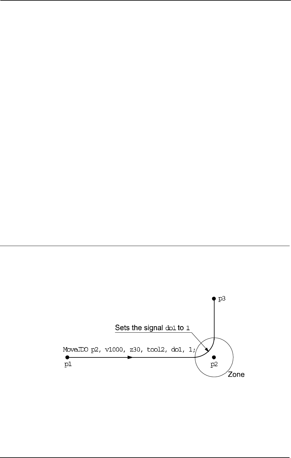
1 Instructions
1.96. MoveJDO - Moves the robot by joint movement and sets digital output in the corner
RobotWare - OS
3HAC 16581-1 Revision: J258
© Copyright 2004-2010 ABB. All rights reserved.
Zone
Data type: zonedata
Zone data for the movement. Zone data describes the size of the generated corner path.
Tool
Data type: tooldata
The tool in use when the robot moves. The tool center point is the point moved to the specified
destination point.
[ \WObj ]
Work Object
Data type:
wobjdata
The work object (coordinate system) to which the robot position in the instruction is related.
This argument can be omitted and if so then the position is related to the world coordinate
system. If, on the other hand, a stationary TCP or coordinated external axes are used then this
argument must be specified.
Signal
Data type: signaldo
The name of the digital output signal to be changed.
Value
Data type: dionum
The desired value of signal (0 or 1).
Program execution
See the instruction
MoveJ for more information about joint movement.
The digital output signal is set/reset in the middle of the corner path for flying points, as
shown in figure below.
The figure shows set/reset of digital output signal in the corner path with
MoveJDO.
xx0500002196
For stop points we recommend the use of“ normal” programming sequence with MoveJ +
SetDO. But when using stop point in instruction MoveJDO, the digital output signal is set/reset
when the robot reaches the stop point.
The specified I/O signal is set/reset in execution mode continuously and stepwise forward,
but not in stepwise backward.
Continued
Continues on next page

1 Instructions
1.96. MoveJDO - Moves the robot by joint movement and sets digital output in the corner
RobotWare - OS
2593HAC 16581-1 Revision: J
© Copyright 2004-2010 ABB. All rights reserved.
Syntax
MoveJDO
[ ToPoint ’:=’ ] < expression (IN) of robtarget >
[ ’\’ ID ’:=’ < expression (IN) of identno >]’,’
[ Speed ’:=’ ] < expression (IN) of speeddata >
[ ’\’ T ’:=’ < expression (IN) of num > ] ’,’
[ Zone ’:=’ ] < expression (IN) of zonedata > ’,’
[ Tool ’:=’ ] < persistent (PERS) of tooldata>
[ ’\’ WObj’ :=’ < persistent (PERS) of wobjdata > ] ’,’
[ Signal ’:=’ ] < variable (VAR) of signaldo>] ´,’
[ Value ´:=’ ] < expression (IN) of dionum > ] ’;’
Related information
For information about See
Other positioning instructions Technical reference manual - RAPID overview,
section RAPID summary - Motion
Moves the robot by joint movement MoveJ - Moves the robot by joint movement on page
253
Definition of velocity speeddata - Speed data on page 1185
Definition of zone data zonedata - Zone data on page 1232
Definition of tools tooldata - Tool data on page 1207
Definition of work objects wobjdata - Work object data on page 1224
Motion in general Technical reference manual - RAPID overview,
section Motion and I/O principles
Coordinate systems Technical reference manual - RAPID overview,
section Motion and I/O principles - Coordinate
systems
Movements with I/O settings Technical reference manual - RAPID overview,
section Synchronization with logical instructions
Continued

1 Instructions
1.97. MoveJSync - Moves the robot by joint movement and executes a RAPID procedure
RobotWare - OS
3HAC 16581-1 Revision: J260
© Copyright 2004-2010 ABB. All rights reserved.
1.97. MoveJSync - Moves the robot by joint movement and executes a RAPID
procedure
Usage
MoveJSync (Move Joint Synchronously) is used to move the robot quickly from one point
to another when that movement does not have to be in a straight line. The specified RAPID
procedure is ordered to execute at the middle of the corner path in the destination point.
The robot and external axes move to the destination position along a non-linear path. All axes
reach the destination position at the same time.
This instruction can only be used in the main task
T_ROB1 or, if in a MultiMove system, in
Motion tasks.
Basic examples
Basic examples of the instruction
MoveJSync are illustrated below.
Example 1
MoveJSync p1, vmax, z30, tool2, "proc1";
The tool center point (TCP) of the tool, tool2, is moved along a non-linear path to the
position,
p1, with speed data vmax and zone data z30. Procedure proc1 is executed in the
middle of the corner path at
p1.
Example 2
MoveJSync p1, vmax, z30, tool2, "MyModule:proc1";
The same as in example 1 above, but here the locally declared procedure proc1 in module
MyModule will be called in the middle of the corner path.
Arguments
MoveJSync ToPoint [\ID] Speed [\T] Zone Tool [\WObj] ProcName
ToPoint
Data type: robtarget
The destination point of the robot and external axes. It is defined as a named position or stored
directly in the instruction (marked with an * in the instruction).
[ \ID ]
Synchronization id
Data type:
identno
This argument must be used in a MultiMove system, if it is a coordinated synchronized
movement, and is not allowed in any other cases.
The specified id number must be the same in all cooperating program tasks. The id number
gives a guarantee that the movements are not mixed up at runtime.
Speed
Data type: speeddata
The speed data that applies to movements. Speed data defines the velocity of the tool center
point, the tool reorientation, and external axes.
Continues on next page
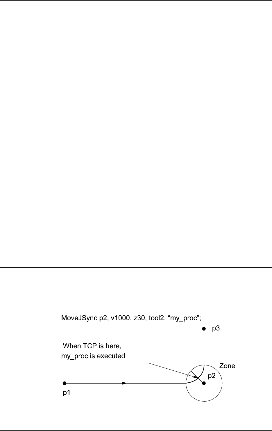
1 Instructions
1.97. MoveJSync - Moves the robot by joint movement and executes a RAPID procedure
RobotWare - OS
2613HAC 16581-1 Revision: J
© Copyright 2004-2010 ABB. All rights reserved.
[ \T ]
Time
Data type:
num
This argument is used to specify the total time in seconds during which the robot moves. It is
then substituted for the corresponding speed data.
Zone
Data type: zonedata
Zone data for the movement. Zone data describes the size of the generated corner path.
Tool
Data type: tooldata
The tool in use when the robot moves. The tool center point is the point moved to the specified
destination point.
[ \WObj ]
Work Object
Data type:
wobjdata
The work object (coordinate system) to which the robot position in the instruction is related.
This argument can be omitted and if so then the position is related to the world coordinate
system. If, on the other hand, a stationary TCP or coordinated external axes are used then this
argument must be specified.
ProcName
Procedure Name
Data type:
string
Name of the RAPID procedure to be executed at the middle of the corner path in the
destination point. The procedure call is a late binding call, and therefore inherits its properties.
Program execution
See the instruction
MoveJ for more information about joint movements.
The specified RAPID procedure is ordered to execute when the TCP reaches the middle of
the corner path in the destination point of the
MoveJSync instruction, as shown in the figure
below.
xx0500002195
Continued
Continues on next page

1 Instructions
1.97. MoveJSync - Moves the robot by joint movement and executes a RAPID procedure
RobotWare - OS
3HAC 16581-1 Revision: J262
© Copyright 2004-2010 ABB. All rights reserved.
For stop points we recommend the use of “normal” programming sequence with MoveJ +
other RAPID instructions in sequence.
The table describes execution of the specified RAPID procedure in different execution
modes:
Limitation
When the robot reaches the middle of the corner path there is normally a delay of 2-30 ms
until the specified
RAPID routine is executed, depending on what type of movement is being
performed at the time.
Switching execution mode after program stop from continuously or cycle to stepwise forward
or backward results in an error. This error tells the user that the mode switch can result in
missed execution of the RAPID procedure in the queue for execution on the path.
Instruction
MoveJSync cannot be used on TRAP level. The specified RAPID procedure
cannot be tested with stepwise execution.
Syntax
MoveJSync
[ ToPoint ’:=’ ] < expression (IN) of robtarget >
[ ’\’ ID ’:=’ < expression (IN) of identno >] ’,’
[ Speed ’:=’ ] < expression (IN) of speeddata >
[ ’\’ T ’:=’ < expression (IN) of num >] ’,’
[ Zone ’:=’ ] < expression (IN) of zonedata >´,´
[ Tool ’:=’ ] < persistent (PERS) of tooldata >
[ ’\’ WObj ´:=’ < persistent (PERS) of wobjdata > ] ’,’
[ ProcName ´:=’ ] < expression (IN) of string > ] ’;’
Execution mode Execution of RAPID procedure
Continuously or Cycle According to this description
Forward step In the stop point
Backward step Not at all
Continued
Continues on next page

1 Instructions
1.97. MoveJSync - Moves the robot by joint movement and executes a RAPID procedure
RobotWare - OS
2633HAC 16581-1 Revision: J
© Copyright 2004-2010 ABB. All rights reserved.
Related information
For information about See
Other positioning instructions Technical reference manual - RAPID overview, section
RAPID summary - Motion
Moves the robot by joint movement MoveJ - Moves the robot by joint movement on page
253
Definition of velocity speeddata - Speed data on page 1185
Definition of zone data zonedata - Zone data on page 1232
Definition of tools tooldata - Tool data on page 1207
Definition of work objects wobjdata - Work object data on page 1224
Motion in general Technical reference manual - RAPID overview, section
Motion and I/O principles
Coordinate systems Technical reference manual - RAPID overview, section
Motion and I/O principles - Coordinate systems
Defines a position related interrupt TriggInt - Defines a position related interrupt on page
588
Continued

1 Instructions
1.98. MoveL - Moves the robot linearly
RobotWare - OS
3HAC 16581-1 Revision: J264
© Copyright 2004-2010 ABB. All rights reserved.
1.98. MoveL - Moves the robot linearly
Usage
MoveL is used to move the tool center point (TCP) linearly to a given destination. When the
TCP is to remain stationary then this instruction can also be used to reorientate the tool.
This instruction can only be used in the main task
T_ROB1 or, if in a MultiMove System, in
Motion tasks.
Basic examples
Basic examples of the instruction
MoveL are illustrated below.
See also More examples on page 266.
Example 1
MoveL p1, v1000, z30, tool2;
The TCP of the tool, tool2, is moved linearly to the position p1, with speed data v1000
and zone data z30.
Example 2
MoveL *, v1000\T:=5, fine, grip3;
The TCP of the tool, grip3, is moved linearly to a stop point stored in the instruction (marked
with an *). The complete movement takes
5 seconds.
Arguments
MoveL [\Conc] ToPoint [\ID] Speed [\V] | [ \T] Zone [\Z] [\Inpos]
Tool [\WObj] [\Corr]
[ \Conc ]
Concurrent
Data type:
switch
Subsequent instructions are executed while the robot is moving. The argument is usually not
used but can be used to avoid unwanted stops caused by overloaded CPU when using fly-by
points. This is useful when the programmed points are very close together at high speeds. The
argument is also useful when, for example, communicating with external equipment and
synchronization between the external equipment and robot movement is not required.
Using the argument
\Conc, the number of movement instructions in succession is limited to
5. In a program section that includes
StorePath-RestoPath, movement instructions with
the argument
\Conc are not permitted.
If this argument is omitted and the
ToPoint is not a stop point then the subsequent instruction
is executed some time before the robot has reached the programmed zone.
This argument can not be used in coordinated synchronized movement in a MultiMove
System.
ToPoint
Data type: robtarget
The destination point of the robot and external axes. It is defined as a named position or stored
directly in the instruction (marked with an * in the instruction).
Continues on next page

1 Instructions
1.98. MoveL - Moves the robot linearly
RobotWare - OS
2653HAC 16581-1 Revision: J
© Copyright 2004-2010 ABB. All rights reserved.
[ \ID ]
Synchronization id
Data type:
identno
This argument must be used in a MultiMove System, if it is a coordinated synchronized
movement, and is not allowed in any other cases.
The specified id number must be the same in all cooperating program tasks. The ID number
gives a guarantee that the movements are not mixed up at runtime.
Speed
Data type: speeddata
The speed data that applies to movements. Speed data defines the velocity for the tool center
point, the tool reorientation, and external axes.
[ \V ]
Velocity
Data type:
num
This argument is used to specify the velocity of the TCP in mm/s directly in the instruction.
It is then substituted for the corresponding velocity specified in the speed data.
[ \T ]
Time
Data type:
num
This argument is used to specify the total time in seconds during which the robot moves. It is
then substituted for the corresponding speed data.
Zone
Data type: zonedata
Zone data for the movement. Zone data describes the size of the generated corner path.
[ \Z ]
Zone
Data type:
num
This argument is used to specify the position accuracy of the robot TCP directly in the
instruction. The length of the corner path is given in mm, which is substituted for the
corresponding zone specified in the zone data.
[ \Inpos ]
In position
Data type:
stoppointdata
This argument is used to specify the convergence criteria for the position of the robot’s TCP
in the stop point. The stop point data substitutes the zone specified in the
Zone parameter.
Tool
Data type: tooldata
The tool in use when the robot moves. The tool center point is the point moved to the specified
destination position.
Continued
Continues on next page

1 Instructions
1.98. MoveL - Moves the robot linearly
RobotWare - OS
3HAC 16581-1 Revision: J266
© Copyright 2004-2010 ABB. All rights reserved.
[ \WObj ]
Work Object
Data type:
wobjdata
The work object (coordinate system) to which the robot position in the instruction is related.
This argument can be omitted and if so then the position is related to the world coordinate
system. If, on the other hand, a stationary tool or coordinated external axes are used then this
argument must be specified in order to perform a linear movement relative to the work object.
[ \Corr ]
Correction
Data type:
switch
Correction data written to a corrections entry by the instruction CorrWrite will be added to
the path and destination position if this argument is present.
Program execution
The robot and external units are moved to the destination position as follows:
• The TCP of the tool is moved linearly at constant programmed velocity.
• The tool is reoriented at equal intervals along the path.
• Uncoordinated external axes are executed at a constant velocity in order for them to
arrive at the destination point at the same time as the robot axes.
If it is not possible to attain the programmed velocity for the reorientation or for the external
axes then the velocity of the TCP will be reduced.
A corner path is usually generated when movement is transferred to the next section of a path.
If a stop point is specified in the zone data then program execution only continues when the
robot and external axes have reached the appropriate position.
More examples
More examples of how to use the instruction
MoveL are illustrated below.
Example 1
MoveL *, v2000 \V:=2200, z40 \Z:=45, grip3;
The TCP of the tool, grip3, is moved linearly to a position stored in the instruction. The
movement is carried out with data set to
v2000 and z40. The velocity and zone size of the
TCP are
2200 mm/s and 45 mm respectively.
Example 2
MoveL p5, v2000, fine \Inpos := inpos50, grip3;
The TCP of the tool, grip3, is moved linearly to a stop point p5. The robot considers it to be
in the point when 50% of the position condition and 50% of the speed condition for a stop
point
fine are satisfied. It waits at most for 2 seconds for the conditions to be satisfied. See
predefined data
inpos50 of data type stoppointdata.
Example 3
MoveL \Conc, *, v2000, z40, grip3;
The TCP of the tool, grip3, is moved linearly to a position stored in the instruction.
Subsequent logical instructions are executed while the robot moves.
Continued
Continues on next page

1 Instructions
1.98. MoveL - Moves the robot linearly
RobotWare - OS
2673HAC 16581-1 Revision: J
© Copyright 2004-2010 ABB. All rights reserved.
Example 4
MoveL start, v2000, z40, grip3 \WObj:=fixture;
The TCP of the tool, grip3, is moved linearly to a position, start. This position is specified
in the object coordinate system for
fixture.
Syntax
MoveL
[ ’\’ Conc ’,’ ]
[ ToPoint’ :=’ ] < expression (IN) of robtarget >
[ ’\’ ID ’:=’ < expression (IN) of identno >] ’,’
[ Speed ’:=’ ] < expression (IN) of speeddata >
[ ’\’ V ’:=’ < expression (IN) of num > ]
| [ ’\’ T’ :=’ < expression (IN) of num > ] ’,’
[Zone ’:=’ ] < expression (IN) of zonedata >
[ ’\’ Z ’:=’< expression (IN) of num > ]
[ ’\’ Inpos’ :=’ < expression (IN) of stoppointdata > ] ´,’
[ Tool ’:=’ ] < persistent (PERS) of tooldata >
[ ’\’ WObj’ :=’ < persistent (PERS) of wobjdata > ]
[ ’\’ Corr ] ’;’
Related information
For information about See
Other positioning instructions Technical reference manual - RAPID overview,
section RAPID summary - Motion
Definition of velocity speeddata - Speed data on page 1185
Definition of zone data zonedata - Zone data on page 1232
Definition of stop point data stoppointdata - Stop point data on page 1189
Definition of tools tooldata - Tool data on page 1207
Definition of work objects wobjdata - Work object data on page 1224
Writes to a corrections entry CorrWrite - Writes to a correction generator on page
77
Motion in general Technical reference manual - RAPID overview,
section Motion and I/O principles
Coordinate systems Technical reference manual - RAPID overview,
section Motion and I/O principles - Coordinate
systems
Concurrent program execution Technical reference manual - RAPID overview,
section Motion and I/O principles - Synchronization
with logical instructions
Continued

1 Instructions
1.99. MoveLDO - Moves the robot linearly and sets digital output in the corner
RobotWare - OS
3HAC 16581-1 Revision: J268
© Copyright 2004-2010 ABB. All rights reserved.
1.99. MoveLDO - Moves the robot linearly and sets digital output in the corner
Usage
MoveLDO (Move Linearly Digital Output) is used to move the tool center point (TCP) linearly
to a given destination. The specified digital output signal is set/reset at the middle of the
corner path.
When the TCP is to remain stationary then this instruction can also be used to reorient the
tool.
This instruction can only be used in the main task
T_ROB1 or, if in a MultiMove system, in
Motion tasks.
Basic examples
Basic examples of the instruction
MoveLDO are illustrated below.
Example 1
MoveLDO p1, v1000, z30, tool2, do1,1;
The TCP of the tool, tool2, is moved linearly to the position p1 with speed data v1000 and
zone data
z30. Output do1 is set in the middle of the corner path at p1.
Arguments
MoveLDO ToPoint [\ID] Speed [\T] Zone Tool [\WObj] Signal Value
ToPoint
Data type: robtarget
The destination point of the robot and external axes. It is defined as a named position or stored
directly in the instruction (marked with an * in the instruction).
[ \ID ]
Synchronization id
Data type:
identno
This argument must be used in a MultiMove system, if coordinated synchronized movement,
and is not allowed in any other cases.
The specified ID number must be the same in all cooperating program tasks. The ID number
gives a guarantee that the movements are not mixed up at runtime.
Speed
Data type: speeddata
The speed data that applies to movements. Speed data defines the velocity for the tool center
point, the tool reorientation, and external axes.
[ \T ]
Time
Data type:
num
This argument is used to specify the total time in seconds during which the robot moves. It is
then substituted for the corresponding speed data.
Continues on next page
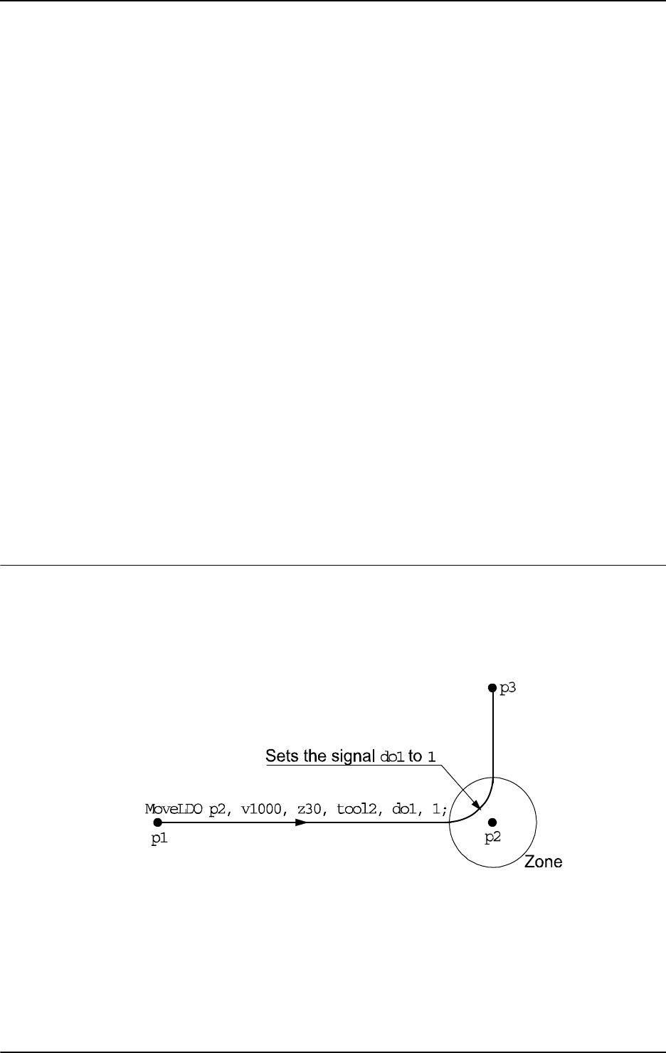
1 Instructions
1.99. MoveLDO - Moves the robot linearly and sets digital output in the corner
RobotWare - OS
2693HAC 16581-1 Revision: J
© Copyright 2004-2010 ABB. All rights reserved.
Zone
Data type: zonedata
Zone data for the movement. Zone data describes the size of the generated corner path.
Tool
Data type: tooldata
The tool in use when the robot moves. The tool center point is the point moved to the specified
destination position.
[ \WObj ]
Work Object
Data type:
wobjdata
The work object (coordinate system) to which the robot position in the instruction is related.
This argument can be omitted and if so then the position is related to the world coordinate
system. If, on the other hand, a stationary TCP or coordinated external axes are used then this
argument must be specified.
Signal
Data type: signaldo
The name of the digital output signal to be changed.
Value
Data type: dionum
The desired value of signal (0 or 1).
Program execution
See the instruction
MoveL for more information about linear movements.
The digital output signal is set/reset in the middle of the corner path for flying points, as
shown in the figure below.
The figure shows set/reset of digital output signal in the corner path with
MoveLDO.
xx0500002193
For stop points we recommend the use of“ normal” programming sequence with MoveL +
SetDO. But when using stop point in instruction MoveLDO, the digital output signal is set/reset
when the robot reaches the stop point.
The specified I/O signal is set/reset in execution mode continuously and stepwise forward,
but not in stepwise backward.
Continued
Continues on next page

1 Instructions
1.99. MoveLDO - Moves the robot linearly and sets digital output in the corner
RobotWare - OS
3HAC 16581-1 Revision: J270
© Copyright 2004-2010 ABB. All rights reserved.
Syntax
MoveLDO
[ ToPoint ’:=’ ] < expression (IN) of robtarget >
[ ’\’ ID ’:=’ < expression (IN) of identno >]’,’
[ Speed ’:=’ ] < expression (IN) of speeddata >
[ ’\’ T ’:=’ < expression (IN) of num > ] ’,’
[ Zone ’:=’ ] < expression (IN) of zonedata > ’,’
[ Tool ’:=’ ] < persistent (PERS) of tooldata >
[ ’\’ WObj’ :=’ ] < persistent (PERS) of wobjdata > ’,’
[ Signal ’:=’ ] < variable (VAR) of signaldo >] ´,’
[ Value ´:=’ ] < expression (IN) of dionum > ] ’;’
Related information
For information about See
Other positioning instructions Technical reference manual - RAPID overview,
section RAPID summary - Motion
Moves the robot linearly MoveL - Moves the robot linearly on page 264
Definition of velocity speeddata - Speed data on page 1185
Definition of zone data zonedata - Zone data on page 1232
Definition of tools tooldata - Tool data on page 1207
Definition of work objects wobjdata - Work object data on page 1224
Motion in general Technical reference manual - RAPID overview,
section Motion and I/O principles
Coordinate systems Technical reference manual - RAPID overview,
section Motion and I/O principles - Coordinate
systems
Movements with I/O settings Technical reference manual - RAPID overview,
section Motion and I/O principles - Synchronization
with logical instructions
Continued

1 Instructions
1.100. MoveLSync - Moves the robot linearly and executes a RAPID procedure
RobotWare - OS
2713HAC 16581-1 Revision: J
© Copyright 2004-2010 ABB. All rights reserved.
1.100. MoveLSync - Moves the robot linearly and executes a RAPID procedure
Usage
MoveLSync (Move Linearly Synchronously) is used to move the tool center point (TCP)
linearly to a given destination. The specified RAPID procedure is ordered to execute at the
middle of the corner path in the destination point.
When the TCP is to remain stationary then this instruction can also be used to reorient the
tool.
This instruction can only be used in the main task
T_ROB1 or, if in a MultiMove system, in
Motion tasks.
Basic examples
Basic examples of the instruction
MoveLSync are illustrated below.
Example 1
MoveLSync p1, v1000, z30, tool2, "proc1";
The TCP of the tool, tool2, is moved linearly to the position p1 with speed data v1000 and
zone data
z30. Procedure proc1 is executed in the middle of the corner path at p1.
Example 2
MoveLSync p1, v1000, z30, tool2, "proc1";
The same as in example 1 above, but here the locally declared procedure proc1 in module
MyModule will be called in the middle of the corner path.
Arguments
MoveLSync ToPoint [\ID] Speed [\T] Zone Tool [\WObj] ProcName
ToPoint
Data type: robtarget
The destination point of the robot and external axes. It is defined as a named position or stored
directly in the instruction (marked with an * in the instruction).
[ \ID ]
Synchronization id
Data type:
identno
This argument must be used in a MultiMove system, if it is a coordinated synchronized
movement, and is not allowed in any other cases.
The specified ID number must be the same in all cooperating program tasks. The ID number
gives a guarantee that the movements are not mixed up at runtime.
Speed
Data type: speeddata
The speed data that applies to movements. Speed data defines the velocity for the tool center
point, the tool reorientation, and external axes.
Continues on next page

1 Instructions
1.100. MoveLSync - Moves the robot linearly and executes a RAPID procedure
RobotWare - OS
3HAC 16581-1 Revision: J272
© Copyright 2004-2010 ABB. All rights reserved.
[ \T ]
Time
Data type:
num
This argument is used to specify the total time in seconds during which the robot moves. It is
then substituted for the corresponding speed data.
Zone
Data type: zonedata
Zone data for the movement. Zone data describes the size of the generated corner path.
Tool
Data type: tooldata
The tool in use when the robot moves. The tool center point is the point moved to the specified
destination position.
[ \WObj ]
Work Object
Data type:
wobjdata
The work object (coordinate system) to which the robot position in the instruction is related.
This argument can be omitted and if so then the position is related to the world coordinate
system. If, on the other hand, a stationary TCP or coordinated external axes are used then this
argument must be specified.
ProcName
Procedure Name
Data type:
string
Name of the RAPID procedure to be executed at the middle of the corner path in the
destination point. The procedure call is a late binding call, and therefore inherits its properties.
Continued
Continues on next page
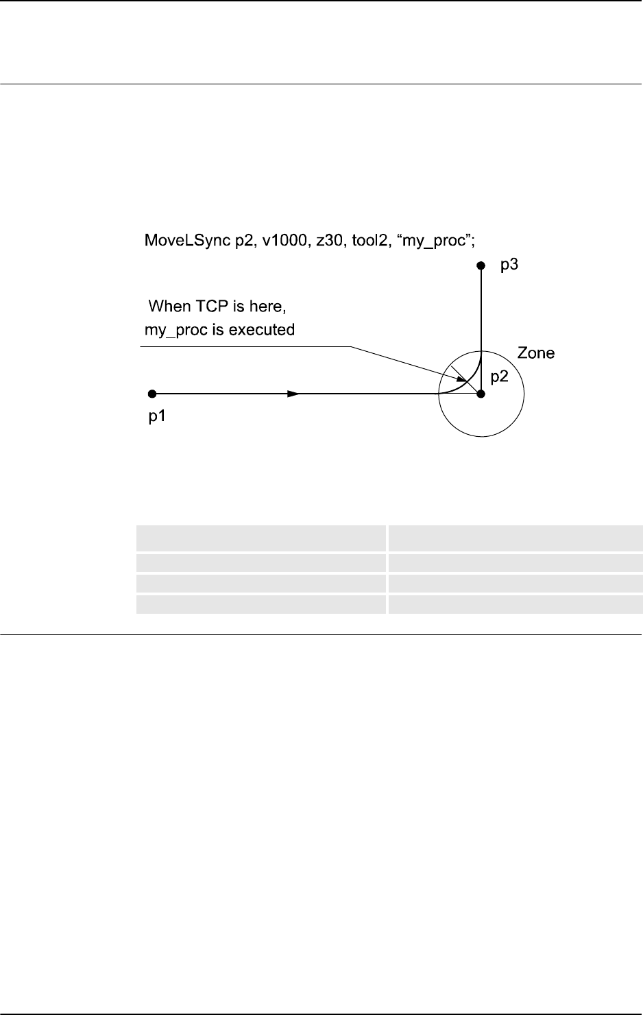
1 Instructions
1.100. MoveLSync - Moves the robot linearly and executes a RAPID procedure
RobotWare - OS
2733HAC 16581-1 Revision: J
© Copyright 2004-2010 ABB. All rights reserved.
Program execution
See the instruction
MoveL for more information about linear movements.
The specified RAPID procedure is ordered to execute when the TCP reaches the middle of
the corner path in the destination point of the
MoveLSync instruction, as shown in the figure
below.
The figure shows that the order to execute the user defined RAPID procedure is done in the
middle of the corner path.
xx0500002194
For stop points we recommend the use of“ normal” programming sequence with MoveL +
other RAPID instructions in sequence.
The table describes execution of the specified RAPID procedure in different execution
modes:
Limitation
When the robot reaches the middle of the corner path there is normally a delay of 2-30 ms
until the specified RAPID routine is executed, depending on what type of movement is being
performed at the time.
Switching execution mode after program stop from continuously or cycle to stepwise forward
or backward results in an error. This error tells the user that the mode switch can result in
missed execution of the RAPID procedure in the queue for execution on the path.
Instruction
MoveLSync cannot be used on TRAP level. The specified RAPID procedure
cannot be tested with stepwise execution.
Execution mode: Execution of RAPID procedure:
Continuously or Cycle According to this description
Forward step In the stop point
Backward step Not at all
Continued
Continues on next page

1 Instructions
1.100. MoveLSync - Moves the robot linearly and executes a RAPID procedure
RobotWare - OS
3HAC 16581-1 Revision: J274
© Copyright 2004-2010 ABB. All rights reserved.
Syntax
MoveLSync
[ ToPoint ’:=’ ] < expression (IN) of robtarget >
[ ’\’ ID ’:=’ < expression (IN) of identno >]’,’
[ Speed ’:=’ ] < expression (IN) of speeddata >
[ ’\’ T ’:=’ < expression (IN) of num > ] ’,’
[ Zone ’:=’ ] < expression (IN) of zonedata > ’,’
[ Tool ’:=’ ] < persistent (PERS) of tooldata >
[ ’\’ WObj ´:=’ < persistent (PERS) of wobjdata > ] ’,’
[ ProcName ´:=’ ] < expression (IN) of string > ] ´;’
Related information
For information about See
Other positioning instructions Technical reference manual - RAPID overview,
section Motion
Moves the robot linearly MoveL - Moves the robot linearly on page 264
Definition of velocity speeddata - Speed data on page 1185
Definition of zone data zonedata - Zone data on page 1232
Definition of tools tooldata - Tool data on page 1207
Definition of work objects wobjdata - Work object data on page 1224
Motion in general Technical reference manual - RAPID overview,
section Motion and I/O principles
Coordinate systems Technical reference manual - RAPID overview,
section Motion and I/O principles - Coordinate
systems
Defines a position related interrupt TriggInt - Defines a position related interrupt on
page 588
Continued

1 Instructions
1.101. MToolRotCalib - Calibration of rotation for moving tool
RobotWare - OS
2753HAC 16581-1 Revision: J
© Copyright 2004-2010 ABB. All rights reserved.
1.101. MToolRotCalib - Calibration of rotation for moving tool
Usage
MToolRotCalib (Moving Tool Rotation Calibration) is used to calibrate the rotation of a
moving tool.
The position of the robot and its movements are always related to its tool coordinate system,
i.e. the TCP and tool orientation. To get the best accuracy it is important to define the tool
coordinate system as correctly as possible.
The calibration can also be done with a manual method using the FlexPendant (described in
Operating manual - IRC5 with FlexPendant, section Programming and testing).
Description
To define the tool orientation, you need a world fixed tip within the robot’s working space.
Before using the instruction
MToolRotCalib some preconditions must be fulfilled:
• The tool that is to be calibrated must be mounted on the robot and defined with correct
component
robhold (TRUE).
• If using the robot with absolute accuracy then the load and center of gravity for the
tool should already be defined.
LoadIdentify can be used for the load definition.
• The TCP value of the tool must already be defined. The calibration can be done with
the instruction
MToolTCPCalib.
• tool0, wobj0, and PDispOff must be activated before jogging the robot.
• Jog the TCP of the actual tool as close as possible to the world fixed tip (origin of the
tool coordinate system) and define a
jointtarget for the reference point RefTip.
• Jog the robot without changing the tool orientation so the world fixed tip is pointing
at some point on the positive z-axis of the tool coordinate system, and define a
jointtarget for point ZPos.
• Optionally jog the robot without changing the tool orientation so the world fixed tip is
pointing at some point on the positive x-axis of the tool coordinate system, and define
a
jointtarget for point XPos.
As a help for pointing out the positive z-axis and x-axis, some type of elongator tool can be
used.
See the figure below for a definition of jointtarget for
RefTip, ZPos, and optional XPos.
xx0500002192
Continues on next page

1 Instructions
1.101. MToolRotCalib - Calibration of rotation for moving tool
RobotWare - OS
3HAC 16581-1 Revision: J276
© Copyright 2004-2010 ABB. All rights reserved.
NOTE!
It is not recommended to modify the positions
RefTip, ZPos, and XPos in the instruction
MToolRotCalib.
Basic examples
Basic examples of the instruction
MToolRotCalib are illustrated below.
Example 1
! Created with the world fixed tip pointing at origin, positive
! z-axis, and positive x-axis of the wanted tool coordinate
! system.
CONST jointtarget pos_tip := [...];
CONST jointtarget pos_z := [...];
CONST jointtarget pos_x := [...];
PERS tooldata tool1:= [ TRUE, [[20, 30, 100], [1, 0, 0 ,0]],
[0.001, [0, 0, 0.001], [1, 0, 0, 0], 0, 0, 0]];
! Instructions for creating or ModPos of pos_tip, pos_z, and pos_x
MoveAbsJ pos_tip, v10, fine, tool0;
MoveAbsJ pos_z, v10, fine, tool0;
MoveAbsJ pos_x, v10, fine, tool0;
! Only tool calibration in the z direction
MToolRotCalib pos_tip, pos_z, tool1;
The tool orientation (tframe.rot) in the z direction of tool1 is calculated. The x and y
directions of the tool orientation are calculated to coincide with the wrist coordinate system.
Example 2
! Calibration with complete tool orientation
MToolRotCalib pos_tip, pos_z \XPos:=pos_x, tool1;
The complete tool orientation (tframe.rot) of tool1 is calculated.
Arguments
MToolRotCalib RefTip ZPos [\XPos]Tool
RefTip
Data type: jointtarget
The point where the TCP of the tool is pointing at the world fixed tip.
ZPos
Data type: jointtarget
The elongator point that defines the positive z direction.
Continued
Continues on next page

1 Instructions
1.101. MToolRotCalib - Calibration of rotation for moving tool
RobotWare - OS
2773HAC 16581-1 Revision: J
© Copyright 2004-2010 ABB. All rights reserved.
[\XPos]
Data type: jointtarget
The elongator point that defines the x positive direction. If this point is omitted then the x and
y directions of the tool will coincide with the corresponding axes in the wrist coordinate
system.
Tool
Data type: tooldata
The persistent variable of the tool that is to be calibrated.
Program execution
The system calculates and updates the tool orientation (
tfame.rot) in the specified tooldata.
The calculation is based on the specified 2 or 3
jointtarget. The remaining data in tooldata
such as TCP
(tframe.trans) is not changed.
Syntax
MToolRotCalib
[ RefTip ’:=’ ] < expression (IN) of jointtarget > ’,’
[ ZPos ’:=’ ] < expression (IN) of jointtarget >
[ ’\’XPos ’:=’ < expression (IN) of jointtarget > ] ’,’
[ Tool ’:=’ ] < persistent (PERS) of tooldata > ’;’
Related information
For information about See
Calibration of TCP for a moving tool MToolTCPCalib - Calibration of TCP for moving
tool on page 278
Calibration of TCP for a stationary tool SToolTCPCalib - Calibration of TCP for stationary
tool on page 507
Calibration of TCP and rotation for a
stationary tool
SToolRotCalib - Calibration of TCP and rotation
for stationary tool on page 504
Continued
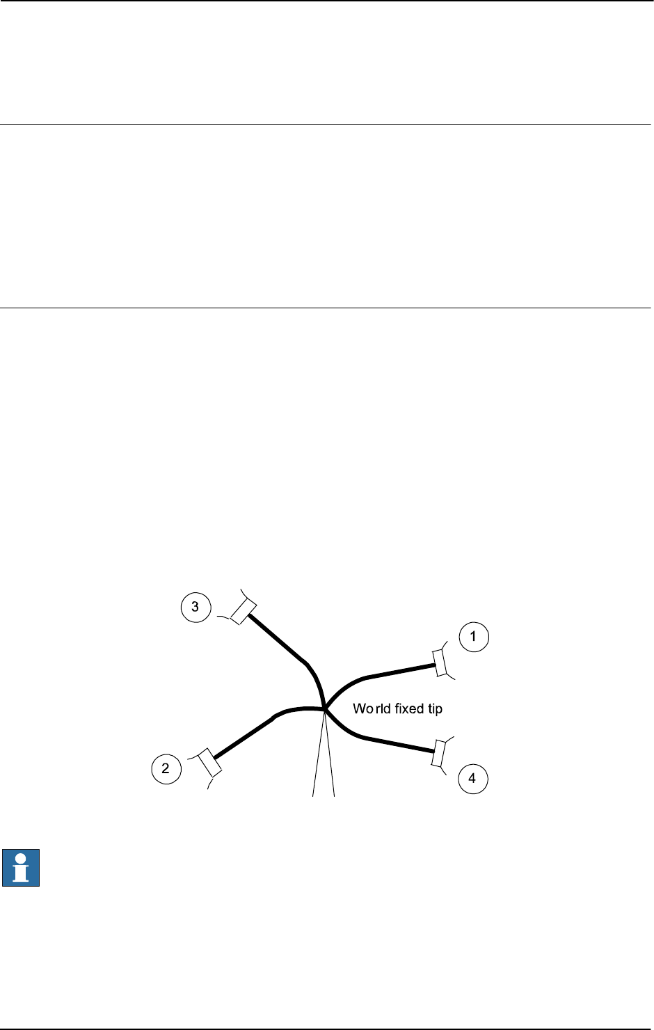
1 Instructions
1.102. MToolTCPCalib - Calibration of TCP for moving tool
RobotWare - OS
3HAC 16581-1 Revision: J278
© Copyright 2004-2010 ABB. All rights reserved.
1.102. MToolTCPCalib - Calibration of TCP for moving tool
Usage
MToolTCPCalib (Moving Tool TCP Calibration) is used to calibrate Tool Center Point -
TCP for a moving tool.
The position of the robot and its movements are always related to its tool coordinate system,
i.e. the TCP and tool orientation. To get the best accuracy it is important to define the tool
coordinate system as correctly as possible.
The calibration can also be done with a manual method using the FlexPendant (described in
Operating manual - IRC5 with FlexPendant, section Programming and testing).
Description
To define the TCP of a tool you need a world fixed tip within the robot’s working space.
Before using the instruction
MToolTCPCalib some preconditions must be fulfilled:
• The tool that is to be calibrated must be mounted on the robot and defined with correct
component
robhold (TRUE).
• If using the robot with absolute accuracy then the load and center of gravity for the
tool should already be defined.
LoadIdentify can be used for the load definition.
• tool0, wobj0, and PDispOff must be activated before jogging the robot.
• Jog the TCP of the actual tool as close as possible to the world fixed tip and define a
jointtarget for the first point p1.
• Define the further three positions (p2, p3, and p4) all with different orientations.
Definition of 4 jointtargets p1....p4, see figure below.
xx0500002191
NOTE!
It is not recommended to modify the positions
Pos1 to Pos4 in the instruction
MToolTCPCalib.
The reorientation between the 4 positions should be as big as possible, putting the robot in
different configurations.Its also good practice to check the quality of the TCP after a
calibration. Which can be performed by reorientation of the tool to check if the TCP is
standing still.
Continues on next page

1 Instructions
1.102. MToolTCPCalib - Calibration of TCP for moving tool
RobotWare - OS
2793HAC 16581-1 Revision: J
© Copyright 2004-2010 ABB. All rights reserved.
Basic examples
Basic examples of the instruction
MToolTCPCalib are illustrated below.
Example 1
! Created with actual TCP pointing at the world fixed tip
CONST jointtarget p1 := [...];
CONST jointtarget p2 := [...];
CONST jointtarget p3 := [...];
CONST jointtarget p4 := [...];
PERS tooldata tool1:= [TRUE, [[0, 0, 0], [1, 0, 0 ,0]], [0.001,
[0, 0, 0.001], [1, 0, 0, 0], 0, 0, 0]];
VAR num max_err;
VAR num mean_err;
...
! Instructions for createing or ModPos of p1 - p4
MoveAbsJ p1, v10, fine, tool0;
MoveAbsJ p2, v10, fine, tool0;
MoveAbsJ p3, v10, fine, tool0;
MoveAbsJ p4, v10, fine, tool0;
...
MToolTCPCalib p1, p2, p3, p4, tool1, max_err, mean_err;
The TCP value (tframe.trans) of tool1 will be calibrated and updated. max_err and
mean_err will hold the max. error in mm from the calculated TCP and the mean error in mm
from the calculated TCP, respectively.
Arguments
MToolTCPCalib Pos1 Pos2 Pos3 Pos4 Tool MaxErr MeanErr
Pos1
Data type: jointtarget
The first approach point.
Pos2
Data type: jointtarget
The second approach point.
Pos3
Data type: jointtarget
The third approach point.
Pos4
Data type: jointtarget
The fourth approach point.
Tool
Data type: tooldata
The persistent variable of the tool that is to be calibrated.
Continued
Continues on next page

1 Instructions
1.102. MToolTCPCalib - Calibration of TCP for moving tool
RobotWare - OS
3HAC 16581-1 Revision: J280
© Copyright 2004-2010 ABB. All rights reserved.
MaxErr
Data type: num
The maximum error in mm for one approach point.
MeanErr
Data type: num
The average distance that the approach points are from the calculated TCP, i.e. how accurately
the robot was positioned relative to the tip.
Program execution
The system calculates and updates the TCP value in the wrist coordinate system
(
tfame.trans) in the specified tooldata. The calculation is based on the specified 4
jointtarget
. The remaining data in tooldata, such as tool orientation (tframe.rot), is not
changed.
Syntax
MToolTCPCalib
[ Pos1 ’:=’ ] < expression (IN) of jointtarget > ’,’
[ Pos2 ’:=’ ] < expression (IN) of jointtarget > ’,’
[ Pos3 ’:=’ ] < expression (IN) of jointtarget > ’,’
[ Pos4 ’:=’ ] < expression (IN) of jointtarget > ’,’
[ Tool ’:=’ ] < persistent (PERS) of tooldata > ’,’
[ MaxErr ’:=’ ] < variable (VAR) of num > ’,’
[ MeanErr’ :=’ ] < variable (VAR) of num > ’;’
Related information
For information about See
Calibration of rotation for a moving tool MToolRotCalib - Calibration of rotation for moving
tool on page 275
Calibration of TCP for a stationary tool SToolTCPCalib - Calibration of TCP for stationary
tool on page 507
Calibration of TCP and rotation for a
stationary tool
SToolRotCalib - Calibration of TCP and rotation for
stationary tool on page 504
Continued

1 Instructions
1.103. Open - Opens a file or serial channel
RobotWare - OS
2813HAC 16581-1 Revision: J
© Copyright 2004-2010 ABB. All rights reserved.
1.103. Open - Opens a file or serial channel
Usage
Open is used to open a file or serial channel for reading or writing.
Basic examples
Basic examples of the instruction
Open are illustrated below.
See also More examples on page 283.
Example 1
VAR iodev logfile;
...
Open "HOME:" \File:= "LOGFILE1.DOC", logfile \Write;
The file LOGFILE1.DOC in unit HOME: is opened for writing. The reference name logfile
is used later in the program when writing to the file.
Example 2
VAR iodev logfile;
...
Open "LOGFILE1.DOC", logfile \Write;
Same result as example 1.The default directory is HOME:.
Arguments
Open Object [\File] IODevice [\Read] | [\Write] | [\Append] [\Bin]
Object
Data type: string
The I/O object (I/O device) that is to be opened, e.g. "HOME:", "TEMP:", "com1:" or
"pc:"(option).
The table describes different I/O devices on the robot controller.
I/O device name Full file path Type of I/O device
"HOME:" or diskhome
1
"/hd0a/xxxx/HOME/"
2
Flashdisk or Hard
Drive
"TEMP:" or disktemp
1
"/hd0a/temp/" Flashdisk or Hard
Drive
"RemovableDisk1:" or usbdisk1
1
"RemovableDisk2:" or usbdisk2
1
"RemovableDisk3:" or usbdisk3
1
"RemovableDisk4:" or usbdisk4
1
"RemovableDisk5:" or usbdisk5
1
"RemovableDisk6:" or usbdisk6
1
"RemovableDisk7:" or usbdisk7
1
"RemovableDisk8:" or usbdisk8
1
"RemovableDisk9:" or usbdisk9
1
"RemovableDisk10:" or usbdisk10
1
"/bd0/"
"/bd1/"
"/bd2/"
"/bd3/"
"/bd4/"
"/bd5/"
"/bd6/"
"/bd7/"
"/bd8/"
"/bd9/"
e.g. USB memory
stick
3
"com1:"
4
"com2:"
4
"com3:"
4
- Serial channel
Continues on next page

1 Instructions
1.103. Open - Opens a file or serial channel
RobotWare - OS
3HAC 16581-1 Revision: J282
© Copyright 2004-2010 ABB. All rights reserved.
1. RAPID string defining device name
2.
"xxxx" means the system name defined when booting the system
3. Note! RemovableDisk1 could be e.g. USB memory on one system but USB floppy on
another.
4. User defined serial channel name defined in system parameters
5. Application protocol, server path defined in system parameters
6. Application protocol, server path defined in system parameters
The following table describes different I/O devices on the virtual controller.
1. RAPID string defining the device name
2.
"xxxx" means the path to the system directory defined when creating the system
3.
"yyyy" means a directory named as System ID
4. Note! RemovableDisk1 could be e.g. USB memory on one system but USB floppy on
another.
[\File]
Data type: string
The name of the file to be opened, e.g. "LOGFILE1.DOC" or "LOGDIR/LOGFILE1.DOC"
The complete path can also be specified in the argument Object, "HOME:/LOGDIR/
LOGFILE.DOC".
IODevice
Data type: iodev
A reference to the file or serial channel to open. This reference is then used for reading from
and writing to the file or serial channel.
[\Read]
Data type: switch
Opens a file or serial channel for reading. When reading from a file the reading is started from
the beginning of the file.
"pc:"
5
"/c:/temp/"
6
Mounted disk
I/O device name Full file path Type of I/O device
"HOME:" or diskhome
1
"/xxxx/HOME/"
2
"TEMP:" or disktemp "/c:/temp/yyyy/"
3
Hard Drive
"RemovableDisk1:" or usbdisk1
"RemovableDisk2:" or usbdisk2
"RemovableDisk3:" or usbdisk3
"RemovableDisk4:" or usbdisk4
"/xxxx/HOME/
RemovableDisk1/"
"/xxxx/HOME/
RemovableDisk2/"
"/xxxx/HOME/
RemovableDisk3/"
"/xxxx/HOME/
RemovableDisk4/"
e.g. USB memory stick
4
I/O device name Full file path Type of I/O device
Continued
Continues on next page

1 Instructions
1.103. Open - Opens a file or serial channel
RobotWare - OS
2833HAC 16581-1 Revision: J
© Copyright 2004-2010 ABB. All rights reserved.
[\Write]
Data type: switch
Opens a file or serial channel for writing. If the selected file already exists then its contents
are deleted. Anything subsequently written is written at the start of the file.
[\Append]
Data type: switch
Opens a file or serial channel for writing. If the selected file already exists then anything
subsequently written is written at the end of the file.
Open a file or serial channel with
\Append and without the \Bin arguments. The instruction
opens a character-based file or serial channel for writing.
Open a file or serial channel with
\Append and \Bin arguments. The instruction opens a
binary file or serial channel for both reading and writing. The arguments
\Read, \Write,
\Append are mutually exclusive. If none of these are specified then the instruction acts in the
same way as the
\Write argument for character-based files or a serial channel (instruction
without
\Bin argument) and in the same way as the \Append argument for binary files or a
serial channel (instruction with
\Bin argument).
[\Bin]
Data type: switch
The file or serial channel is opened in a binary mode. If none of the arguments \Read,
\Write or \Append are specified then the instruction opens a binary file or serial channel
for both reading and writing, with the file pointer at the end of the file.
The
Rewind instruction can be used to set the file pointer to the beginning of the file if
desirable.
The set of instructions to access a binary file or serial channel is different from the set of
instructions to access a character-based file.
More examples
More examples of how to use the instruction
Open are illustrated below.
Example 1
VAR iodev printer;
...
Open "com2:", printer \Bin;
WriteStrBin printer, "This is a message to the printer\0D";
Close printer;
The serial channel com2: is opened for binary reading and writing. The reference name
printer is used later when writing to and closing the serial channel.
Continued
Continues on next page

1 Instructions
1.103. Open - Opens a file or serial channel
RobotWare - OS
3HAC 16581-1 Revision: J284
© Copyright 2004-2010 ABB. All rights reserved.
Program execution
The specified file or serial channel is opened so that it is possible to read from or write to it.
It is possible to open the same physical file several times at the same time but each invocation
of the
Open instruction will return a different reference to the file (data type iodev). E.g. it
is possible to have one write pointer and one different read pointer to the same file at the same
time.
The iodev variable used when opening a file or serial channel must be free from use. If it has
been used previously to open a file then this file must be closed prior to issuing a new
Open
instruction with the same iodev variable.
At Program Stop and moved PP to Main, any open file or serial channel in the program task
will be closed and the I/O descriptor in the variable of type
iodev will be reset. An exception
to the rule is variables that are installed shared in the system of type global VAR or LOCAL
VAR. Such file or serial channel belonging to the whole system will still be open.
At power fail restart, any open file or serial channel in the system will be closed and the I/O
descriptor in the variable of type
iodev will be reset.
Error handling
If a file cannot be opened then the system variable
ERRNO is set to ERR_FILEOPEN. This error
can then be handled in the error handler.
Syntax
Open [Object’ :=’] <expression (IN) of string>
[’\’File’:=’ <expression (IN) of string>] ’,’
[IODevice ’:=’] <variable (VAR) of iodev>
[’\’Read] |
[’\’Write] |
[’\’Append]
[’\’Bin] ’;’
Related information
For information about See
Writing to, reading from and closing files
or serial channels
Technical reference manual - RAPID overview,
section RAPID summary - Communication
Continued

1 Instructions
1.104. OpenDir - Open a directory
RobotWare - OS
2853HAC 16581-1 Revision: J
© Copyright 2004-2010 ABB. All rights reserved.
1.104. OpenDir - Open a directory
Usage
OpenDir is used to open a directory for further investigation.
Basic examples
Basic examples of the instruction
OpenDir are illustrated below.
Example 1
PROC lsdir(string dirname)
VAR dir directory;
VAR string filename;
OpenDir directory, dirname;
WHILE ReadDir(directory, filename) DO
TPWrite filename;
ENDWHILE
CloseDir directory;
ENDPROC
This example prints out the names of all files or subdirectories under the specified directory.
Arguments
OpenDir Dev Path
Dev
Data type: dir
A variable with reference to the directory, fetched by OpenDir. This variable is then used for
reading from the directory.
Path
Data type: string
Path to the directory.
Limitations
Open directories should always be closed by the user after reading (instruction
CloseDir).
Error handling
If the path points to a non-existing directory or if there are too many directories open at the
same time then the system variable
ERRNO is set to ERR_FILEACC. This error can then be
handled in the error handler.
Syntax
OpenDir
[ Dev’:=’ ] < variable (VAR) of dir>’,’
[ Path’:=’ ] < expression (IN) of string>’;’
Continues on next page

1 Instructions
1.104. OpenDir - Open a directory
RobotWare - OS
3HAC 16581-1 Revision: J286
© Copyright 2004-2010 ABB. All rights reserved.
Related information
For information about See
Directory dir - File directory structure on page 1103
Make a directory MakeDir - Create a new directory on page 218
Remove a directory RemoveDir - Delete a directory on page 355
Read a directory ReadDir - Read next entry in a directory on page
944
Close a directory CloseDir - Close a directory on page 56
Remove a file RemoveFile - Delete a file on page 356
Rename a file RenameFile - Rename a file on page 357
Continued

1 Instructions
1.105. PackDNHeader - Pack DeviceNet Header into rawbytes data
RobotWare - OS
2873HAC 16581-1 Revision: J
© Copyright 2004-2010 ABB. All rights reserved.
1.105. PackDNHeader - Pack DeviceNet Header into rawbytes data
Usage
PackDNHeader is used to pack the header of a DeviceNet explicit message into a container
of type
rawbytes.
The data part of the DeviceNet message can afterwards be set with the instruction
PackRawBytes.
Basic examples
Basic examples of the instruction
PackDNHeader are illustrated below.
Example 1
VAR rawbytes raw_data;
PackDNHeader "0E", "6,20 01 24 01 30 06,9,4", raw_data;
Pack the header for DeviceNet explicit message with service code "0E" and path string
"6,20 01 24 01 30 06,9,4" into raw_data corresponding to get the serial number from
some I/O unit.
This message is ready to send without filling the message with additional data.
Example 2
VAR rawbytes raw_data;
PackDNHeader "10", "20 1D 24 01 30 64", raw_data;
Pack the header for DeviceNet explicit message with service code "10" and path string
"20 1D 24 01 30 64" into raw_data corresponding to set the filter time for the rising
edge on insignal 1 for some I/O unit.
This message must be increased with data for the filter time. This can be done with instruction
PackRawBytes starting at index RawBytesLen(raw_data)+1 (done after
PackDNHeader).
Arguments
PackDNHeader Service Path RawData
Service
Data type: string
The service to be done such as get or set attribute. To be specified with a hexadecimal code
in a string e.g.
"IF".
The values for the
Service is found in the EDS file. For a more detailed description see the
Open DeviceNet Vendor Association ODVA DeviceNet Specification revision 2.0.
String length 2 characters
Format ’0’ -’ 9’, ’a’ -’f’, ’A’ - ’F’
Range "00" - "FF
Continues on next page

1 Instructions
1.105. PackDNHeader - Pack DeviceNet Header into rawbytes data
RobotWare - OS
3HAC 16581-1 Revision: J288
© Copyright 2004-2010 ABB. All rights reserved.
Path
Data type: string
The values for the Path is found in the EDS file. For a more detailed description see the Open
DeviceNet Vendor Association ODVA DeviceNet Specification revision 2.0.
Support for both long string format (e.g. "
6,20 1D 24 01 30 64,8,1") and short string
format (e.g. "
20 1D 24 01 30 64").
RawData
Data type: rawbytes
Variable container to be packed with message header data starting at index 1 in RawData.
Program execution
During program execution the DeviceNet message
RawData container is:
• first completely cleared
• and then the header part is packed with data
Format DeviceNet Header
The instruction
PackDNHeader will create a DeviceNet message header with following
format:
The data part of the DeviceNet message can afterwards be set with the instruction
PackRawBytes starting at index fetched with (RawBytesLen(my_rawdata)+1).
Syntax
PackDNHeader
[Service ´:=´ ] < expression (IN) of string> ´,´
[Path ´:=´ ] < expression (IN) of string> ´,´
[RawData ´:=´ ] < variable (VAR) of rawbytes> ´;´
RawData
Header Format
No of
bytes
Note
Format 1 Internal IRC5 code for DeviceNet
Service 1 Hex code for service
Size of Path 1 In bytes
Path x ASCII chars
Continued
Continues on next page

1 Instructions
1.105. PackDNHeader - Pack DeviceNet Header into rawbytes data
RobotWare - OS
2893HAC 16581-1 Revision: J
© Copyright 2004-2010 ABB. All rights reserved.
Related information
For information about See
rawbytes data rawbytes - Raw data on page 1165
Get the length of rawbytes data RawBytesLen - Get the length of rawbytes data on
page 940
Clear the contents of rawbytes data ClearRawBytes - Clear the contents of rawbytes
data on page 49
Copy the contents of rawbytes data CopyRawBytes - Copy the contents of rawbytes data
on page 67
Pack data to rawbytes data PackRawBytes - Pack data into rawbytes data on
page 290
Write rawbytes data WriteRawBytes - Write rawbytes data on page 725
Read rawbytes data ReadRawBytes - Read rawbytes data on page 352
Unpack data from rawbytes data UnpackRawBytes - Unpack data from rawbytes data
on page 658
Bit/Byte Functions Technical reference manual - RAPID overview,
section RAPID summary - Mathematics - Bit
Functions
String functions Technical reference manual - RAPID overview,
section RAPID Summary - String Functions
Continued

1 Instructions
1.106. PackRawBytes - Pack data into rawbytes data
RobotWare - OS
3HAC 16581-1 Revision: J290
© Copyright 2004-2010 ABB. All rights reserved.
1.106. PackRawBytes - Pack data into rawbytes data
Usage
PackRawBytes is used to pack the contents of variables of type num, dnum, byte, or string
into a container of type
rawbytes.
Basic examples
Basic examples of the instruction
PackRawBytes are illustrated below.
VAR rawbytes raw_data;
VAR num integer := 8;
VAR dnum bigInt := 4294967295;
VAR num float := 13.4;
VAR byte data1 := 122;
VAR byte byte1;
VAR string string1:="abcdefg";
PackDNHeader "10", "20 1D 24 01 30 64", raw_data;
Pack the header for DeviceNet into raw_data.
Then pack requested field bus data in
raw_data with PackRawBytes. The example below
shows how different data can be added.
Example 1
PackRawBytes integer, raw_data, (RawBytesLen(raw_data)+1) \IntX :=
DINT;
The contents of the next 4 bytes after the header in raw_data will be 8 decimal.
Example 2
PackRawBytes bigInt, raw_data, (RawBytesLen(raw_data)+1) \IntX :=
UDINT;
The contents of the next 4 bytes after the header in raw_data will be 4294967295 decimal.
Example 3
PackRawBytes bigInt, raw_data, (RawBytesLen(raw_data)+1) \IntX :=
LINT;
The contents of the next 8 bytes after the header in raw_data will be 4294967295 decimal.
Example 4
PackRawBytes float, raw_data, RawBytesLen(raw_data)+1) \Float4;
The contents of the next 4 bytes in raw_data will be 13.4 decimal.
Example 5
PackRawBytes data1, raw_data, (RawBytesLen(raw_data)+1) \ASCII;
The contents of the next byte in raw_data will be 122, the ASCII code for "z".
Example 6
PackRawBytes string1, raw_data, (RawBytesLen(raw_data)+1) \ASCII;
The contents of next 7 bytes in raw_data will be "abcdefg", coded in ASCII.
Continues on next page

1 Instructions
1.106. PackRawBytes - Pack data into rawbytes data
RobotWare - OS
2913HAC 16581-1 Revision: J
© Copyright 2004-2010 ABB. All rights reserved.
Example 7
byte1 := StrToByte("1F" \Hex);
PackRawBytes byte1, raw_data, (RawBytesLen(raw_data)+1) \Hex1;
The contents of the next byte in raw_data will be "1F", hexadecimal.
Arguments
PackRawBytes Value RawData [ \Network ] StartIndex
[ \Hex1 ] | [ \IntX ] | [ \Float4 ] | [ \ASCII ]
Value
Data type: anytype
Data to be packed into RawData.
Allowed data types are:
num, dnum, byte, or string. Array can not be used.
RawData
Data type: rawbytes
Variable container to be packed with data.
[ \Network ]
Data type: switch
Indicates that integer and float shall be packed in big-endian (network order)
representation in
RawData. ProfiBus and InterBus use big-endian.
Without this switch,
integer and float will be packed in little-endian (not network order)
representation in
RawData. DeviceNet uses little-endian.
Only relevant together with option parameter
\IntX - UINT, UDINT, INT, DINT and
\Float4.
StartIndex
Data type: num
StartIndex
between 1 and 1024 indicates where the first byte contained in Value shall be
placed in
RawData.
[ \Hex1 ]
Data type: switch
The Value to be packed has byte format and shall be converted to hexadecimal format and
stored in 1 byte in
RawData.
[ \IntX ]
Data type: inttypes
The Value to be packed has num or dnum format. It is an integer and shall be stored in
RawData according to this specified constant of data type inttypes .
See Predefined data on page 293.
[ \Float4 ]
Data type: switch
The Value to be packed has num format and shall be stored as float, 4 bytes, in RawData.
Continued
Continues on next page

1 Instructions
1.106. PackRawBytes - Pack data into rawbytes data
RobotWare - OS
3HAC 16581-1 Revision: J292
© Copyright 2004-2010 ABB. All rights reserved.
[ \ASCII ]
Data type: switch
The Value to be packed has byte or string format.
If the
Value to be packed has byte format then it will be stored in RawData as 1 byte
interpreting
Value as ASCII code for a character.
If the
Value to be packed has string format (1-80 characters) then it will be stored in
RawData as ASCII characters with the same number of characters as contained in Value.
String data is not
NULL terminated by the system in data of type rawbytes. It is up to the
programmer to add string header if necessary (required for DeviceNet).
One of the arguments
\Hex1, \IntX, \Float4, or \ASCII must be programmed.
The following combinations are allowed:
*) Must be an integer within the value range of selected symbolic constant
USINT, UINT,
UDINT, SINT, INT or DINT.
**) Must be an integer within the value range of selected symbolic constant
USINT, UINT,
UDINT, ULINT, SINT, INT, DINT or LINT.
Program execution
During program execution the data is packed from the variable of type
anytype into a
container of type
rawbytes.
The current length of valid bytes in the
RawData variable is set to:
• (StartIndex + packed_number_of_bytes - 1)
• The current length of valid bytes in the RawData variable is not changed if the
complete pack operation is done inside the old current length of valid bytes in the
RawData variable.
Data type of Value: Allowed option parameters:
num *) \IntX
dnum **) \IntX
num \Float4
string \ASCII (1-80 characters)
byte \Hex1 \ASCIIob
Continued
Continues on next page

1 Instructions
1.106. PackRawBytes - Pack data into rawbytes data
RobotWare - OS
2933HAC 16581-1 Revision: J
© Copyright 2004-2010 ABB. All rights reserved.
Predefined data
The following symbolic constants of the data type
inttypes are predefined and can be used
to specify the integer in parameter
\IntX.
*) RAPID limitation for storage of integer in data type
num.
**) RAPID limitation for storage of integer in data type
dnum.
***) Range when using a dnum variable and inttype
DINT.
****) Range when using a dnum variable and inttype
UDINT.
Syntax
PackRawBytes
[Value ´:=´ ] < expression (IN) of anytype> ´,´
[RawData ´:=´ ] < variable (VAR) of rawbytes>
[ ’\’ Network ] ´,´
[StartIndex ´:=´ ] < expression (IN) of num>
[ ’\’ Hex1 ]
| [ ’\’ IntX’ :=’ < expression (IN) of inttypes>]
|[ ’\’ Float4 ]
| [ ’\’ ASCII]’ ;’
Symbolic
constant
Constant
value
Integer format Integer value range
USINT 1 Unsigned 1 byte integer 0 ... 255
UINT 2 Unsigned 2 byte integer 0 ... 65 535
UDINT 4 Unsigned 4 byte integer 0 ... 8 388 608 *)
0 ... 4 294 967 295 ****)
ULINT 8 Unsigned 8 byte integer 0 ... 4 503 599 627 370 496**)
SINT - 1 Signed 1 byte integer - 128... 127
INT - 2 Signed 2 byte integer - 32 768 ... 32 767
DINT - 4 Signed 4 byte integer - 8 388 607 ... 8 388 608 *)
-2 147 483 648 ... 2 147 483
647 ***)
LINT - 8 Signed 8 byte integer - 4 503 599 627 370 496... 4
503 599 627 370 496 **)
Continued
Continues on next page

1 Instructions
1.106. PackRawBytes - Pack data into rawbytes data
RobotWare - OS
3HAC 16581-1 Revision: J294
© Copyright 2004-2010 ABB. All rights reserved.
Related information
For information about See
rawbytes data rawbytes - Raw data on page 1165
Get the length of rawbytes data RawBytesLen - Get the length of rawbytes data
on page 940
Clear the contents of rawbytes data ClearRawBytes - Clear the contents of
rawbytes data on page 49
Copy the contents of rawbytes data CopyRawBytes - Copy the contents of
rawbytes data on page 67
Pack DeviceNet header into rawbytes
data
PackDNHeader - Pack DeviceNet Header into
rawbytes data on page 287
Write rawbytes data WriteRawBytes - Write rawbytes data on page
725
Read rawbytes data ReadRawBytes - Read rawbytes data on page
352
Unpack data from rawbytes data UnpackRawBytes - Unpack data from
rawbytes data on page 658
Bit/Byte Functions Technical reference manual - RAPID overview,
section RAPID Summary - Mathematics -
Bit Functions
String functions Technical reference manual - RAPID overview,
section RAPID Summary - String Functions
Continued
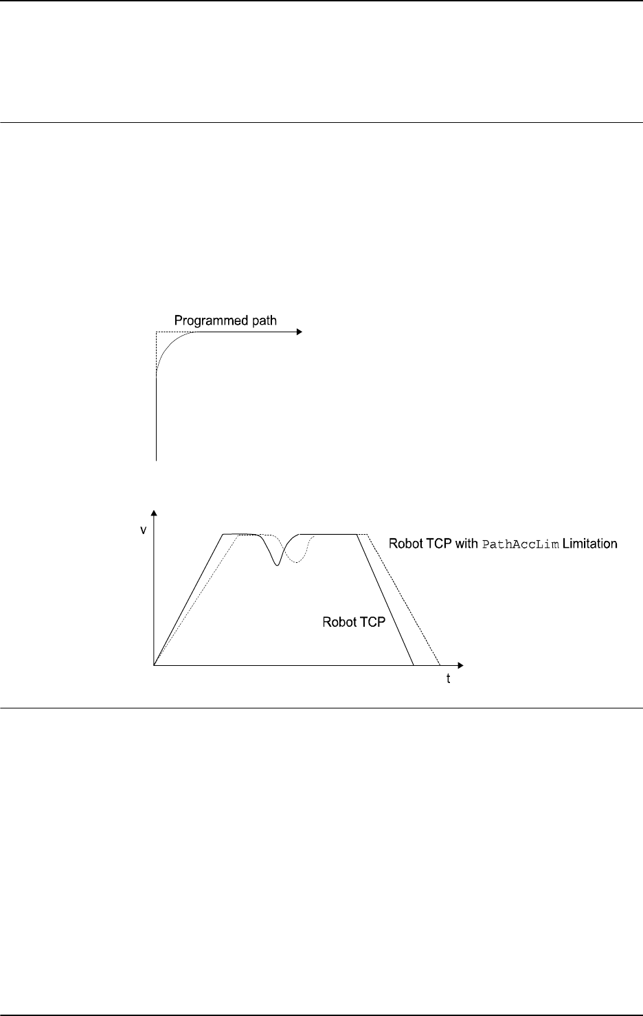
1 Instructions
1.107. PathAccLim - Reduce TCP acceleration along the path
RobotWare - OS
2953HAC 16581-1 Revision: J
© Copyright 2004-2010 ABB. All rights reserved.
1.107. PathAccLim - Reduce TCP acceleration along the path
Usage
PathAccLim (Path Acceleration Limitation) is used to set or reset limitations on TCP
acceleration and/or TCP deceleration along the movement path.
The limitation will be performed along the movement path, i.e. the acceleration in the path
frame. It is the tangential acceleration/deceleration in the path direction that will be limited.
The instruction does not limit the total acceleration of the equipment, i.e. the acceleration in
world frame, so it can not be directly used to protect the equipment from large accelerations.
This instruction can only be used in the main task
T_ROB1 or, if in a MultiMove system, in
Motion tasks.
xx0500002184
Basic examples
Basic examples of the instruction
PathAccLim are illustrated below.
See also More examples on page 296.
Example 1
PathAccLim TRUE \AccMax := 4, TRUE \DecelMax := 4;
TCP acceleration and TCP deceleration are limited to 4 m/s
2
.
Example 2
PathAccLim FALSE, FALSE;
The TCP acceleration and deceleration is reset to maximum (default).
Continues on next page
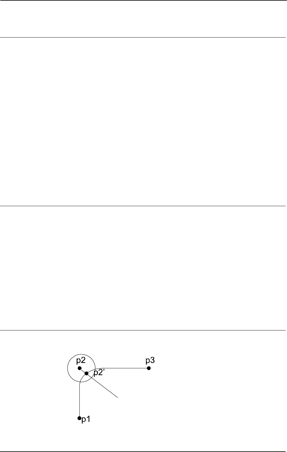
1 Instructions
1.107. PathAccLim - Reduce TCP acceleration along the path
RobotWare - OS
3HAC 16581-1 Revision: J296
© Copyright 2004-2010 ABB. All rights reserved.
Arguments
PathAccLim AccLim [\AccMax] DecelLim [\DecelMax]
AccLim
Data type: bool
TRUE if there is to be a limitation of the acceleration, FALSE otherwise.
[ \AccMax ]
Data type: num
The absolute value of the acceleration limitation in m/s
2
. Only to be used when AccLim is
TRUE.
DecelLim
Data type: bool
TRUE if there is to be a limitation of the deceleration, FALSE otherwise.
[ \DecelMax ]
Data type: num
The absolute value of the deceleration limitation in m/s
2
. Only to be used when DecelLim is
TRUE.
Program execution
The acceleration/deceleration limitations applies for the next executed robot segment and is
valid until a new
PathAccLim instruction is executed.
The maximum acceleration/deceleration (
PathAccLim FALSE, FALSE) are automatically
set
• at a cold start-up
• when a new program is loaded
• when starting program execution from the beginning.
If there is a combination of instructions
AccSet and PathAccLim the system reduces the
acceleration/deceleration in the following order:
• according AccSet
• according PathAccLim
More examples
More examples of how to use the instruction
PathAccLim are illustrated below.
xx0500002183
Continued
Continues on next page

1 Instructions
1.107. PathAccLim - Reduce TCP acceleration along the path
RobotWare - OS
2973HAC 16581-1 Revision: J
© Copyright 2004-2010 ABB. All rights reserved.
Example 1
MoveL p1, v1000, fine, tool0;
PathAccLim TRUE\AccMax := 4, FALSE;
MoveL p2, v1000, z30, tool0;
MoveL p3, v1000, fine, tool0;
PathAccLim FALSE, FALSE;
TCP acceleration is limited to 4 m/s
2
between p1 and p3.
Example 2
MoveL p1, v1000, fine, tool0;
MoveL p2, v1000, z30, tool0;
PathAccLim TRUE\AccMax :=3, TRUE\DecelMax := 4;
MoveL p3, v1000, fine, tool0;
PathAccLim FALSE, FALSE;
TCP acceleration is limited to 3 m/s
2
between p2’ and p3.
TCP deceleration is limited to
4 m/s
2
between p2’ and p3.
Error handling
If the parameters
\AccMax or \DecelMax is set to a value too low, the system variable
ERRNO is set to ERR_ACC_TOO_LOW. This error can then be handled in the error handler.
Limitations
The minimum acceleration/deceleration allowed is
0.5 m/s
2
.
Syntax
PathAccLim
[ AccLim ’:=’ ] < expression (IN) of bool >
[´\’AccMax’ :=’ <expression (IN) of num >]’,’
[DecelLim ´:=’ ] < expression (IN) of bool>
[´\’DecelMax ´:=’ <expression (IN) of num >]’;’
Related information
For information about See
Positioning instructions Technical reference manual - RAPID overview,
section RAPID summary - Motion
Motion settings data motsetdata - Motion settings data on page 1141
Reduction of acceleration AccSet - Reduces the acceleration on page 15
Continued

1 Instructions
1.108. PathRecMoveBwd - Move path recorder backwards
Path Recovery
3HAC 16581-1 Revision: J298
© Copyright 2004-2010 ABB. All rights reserved.
1.108. PathRecMoveBwd - Move path recorder backwards
Usage
PathRecMoveBwd is used to move the robot backwards along a recorded path.
Basic examples
Basic examples of the instruction
PathRecMoveBwd are illustrated below.
See also More examples on page 300.
Example 1
VAR pathrecid fixture_id;
PathRecMoveBwd \ID:=fixture_id \ToolOffs:=[0, 0, 10] \Speed:=v500;
The robot is moved backwards to the position in the program where the instruction
PathRecStart planted the fixture_id identifier. The TCP offset is 10 mm in Z direction
and the speed is set to 500 mm/s.
Arguments
PathRecMoveBwd [\ID] [\ToolOffs] [\Speed]
[\ID]
Identifier
Data type:
pathrecid
Variable that specifies the ID position to move backward to. Data type pathrecid is a non-
value type, only used as an identifier for naming the recording position.
If no ID position is specified then the backward movement is in a single system done to the
closest recorded ID position. But in a MultiMove Synchronized Mode, the backward
movements is done to the closest of the following positions:
• Back to the position where the synchronized movement started
• Back to the closest recorded ID position
[\ToolOffs]
Tool Offset
Data type:
pos
Provides clearance offset for TCP during motion. A cartesian offset coordinate is applied to
the TCP coordinates. Positive Z offset value indicates clearance. This is useful when the robot
runs a process adding material. If running synchronized motion then all or none of the
mechanical units needs to use the argument. If no offset is desired for some of the mechanical
units then a zero offset can be applied. Even non TCP mechanical units need to use the
argument if a TCP robot in a different task is used.
[\Speed]
Data type: speeddata
Speed replaces the speed original used during forward motion. Speeddata defines the velocity
for the tool center point, the tool reorientation, and the external axis. If present, this speed will
be used throughout the backward movement. If omitted, the backward motion will execute
with the speed in the original motion instructions.
Continues on next page

1 Instructions
1.108. PathRecMoveBwd - Move path recorder backwards
Path Recovery
2993HAC 16581-1 Revision: J
© Copyright 2004-2010 ABB. All rights reserved.
Program execution
The path recorder is activated with the
PathRecStart instruction. After the recorder has
been started then all move instructions will be recorded and the robot can be moved
backwards along its recorded path at any point by executing
PathRecMoveBwd.
Synchronized motion
Running the path recorder in synchronization motion adds a few considerations.
• All tasks involved in the synchronization recorded motion must order
PathRecMoveBwd before any of the robots start to move.
• All synchronization handling is recorded and executed in reverse. For example, if
PathRecMoveBwd is ordered from within a synchronization block to an independent
position then the path recorder will automatically change state to independent at the
SyncMoveOn instruction.
• SyncMoveOn is considered as a breakpoint without path identifier. That is, if the path
recorder has been started by means of
PathRecStart and PathRecMoveBwd without
the optional argument
\ID is executed within a synchronized motion block, then the
robot will move backwards to the position the robot was at when
SyncMoveOn was
executed. Since the backward movement stops before
SyncMoveOn, the state will be
changed to independent.
• WaitSyncTask is considered as a breakpoint without path identifier. That is, if the
path recorder has been started by the means of
PathRecStart and
PathRecMoveBwd is executed then the robot will move back no longer than to the
position the robot was at when
WaitSyncTask was executed.
Continued
Continues on next page

1 Instructions
1.108. PathRecMoveBwd - Move path recorder backwards
Path Recovery
3HAC 16581-1 Revision: J300
© Copyright 2004-2010 ABB. All rights reserved.
More examples
More examples of how to use the instruction
PathRecMoveBwd are illustrated below.
Example 1 - Independent motion
VAR pathrecid safe_id;
CONST robtarget p0 := [...];
...
CONST robtarget p4 := [...];
VAR num choice;
MoveJ p0, vmax, z50, tool1;
PathRecStart safe_id;
MoveJ p1, vmax, z50, tool1;
MoveL p2, vmax, z50, tool1;
MoveL p3, vmax, z50, tool1;
MoveL p4, vmax, z50, tool1;
ERROR:
TPReadFK choice,"Go to
safe?",stEmpty,stEmpty,stEmpty,stEmpty,"Yes";
IF choice=5 THEN
IF PathRecValidBwd(\ID:=safe_id) THEN
StorePath;
PathRecMoveBwd \ID:=safe_id \ToolOffs:=[0, 0 , 10];
Stop;
!Fix problem
PathRecMoveFwd;
RestoPath;
StartMove;
RETRY;
ENDIF
ENDIF
Continued
Continues on next page
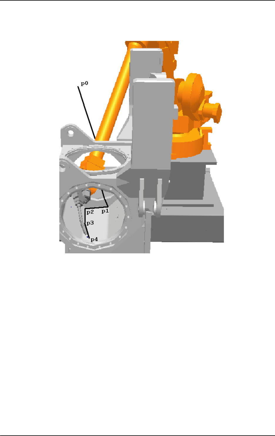
1 Instructions
1.108. PathRecMoveBwd - Move path recorder backwards
Path Recovery
3013HAC 16581-1 Revision: J
© Copyright 2004-2010 ABB. All rights reserved.
xx0500002135
This example shows how the path recorder can be utilized to extract the robot from narrow
spaces upon error without programming a designated path.
A part is being manufactured. At the approach point,
p0, the path recorder is started and
given the path recorder identifier
safe_id. Assume that when the robot moves from p3 to
p4 that a recoverable error arises. At that point the path is stored by executing StorePath.
By storing the path the error handler can start a new movement and later on restart the original
movement. When the path has been stored the path recorder is used to move the robot out to
the safe position,
p0, by executing PathRecMoveBwd.
Note that a tool offset is applied to provide clearance from, for example, a newly added weld.
When the robot has been moved out the operator can do what is necessary to fix the error (for
example clean the torch of welding). Then the robot is moved back to the error location by
the means of
PathRecMoveFwd. At the error location the path level is switched back to base
level by
RestoPath and a retry attempt is made.
Continued
Continues on next page

1 Instructions
1.108. PathRecMoveBwd - Move path recorder backwards
Path Recovery
3HAC 16581-1 Revision: J302
© Copyright 2004-2010 ABB. All rights reserved.
Example 2 - Synchronized motion
T_ROB1
VAR pathrecid HomeROB1;
CONST robtarget pR1_10:=[...];
...
CONST robtarget pR1_60:=[...];
PathRecStart HomeROB1;
MoveJ pR1_10, v1000, z50, tGun;
MoveJ pR1_20, v1000, z50, tGun;
MoveJ pR1_30, v1000, z50, tGun;
SyncMoveOn sync1, tasklist;
MoveL pR1_40 \ID:=1, v1000, z50, tGun\wobj:=pos1;
MoveL pR1_50 \ID:=2, v1000, z50, tGun\wobj:=pos1;
MoveL pR1_60 \ID:=3, v1000, z50, tGun\wobj:=pos1;
SyncMoveOff sync2;
ERROR
StorePath \KeepSync;
TEST ERRNO
CASE ERR_PATH_STOP:
PathRecMoveBwd \ID:= HomeROB1\ToolOffs:=[0,0,10];
ENDTEST
!Perform service action
PathRecMoveFwd \ToolOffs:=[0,0,10];
RestoPath;
StartMove;
T_ROB2
VAR pathrecid HomeROB2;
CONST robtarget pR2_10:=[...];
...
CONST robtarget pR2_50:=[...];
PathRecStart HomeROB2;
MoveJ pR2_10, v1000, z50, tGun;
MoveJ pR2_20, v1000, z50, tGun;
SyncMoveOn sync1, tasklist;
MoveL pR2_30 \ID:=1, v1000, z50, tGun\wobj:=pos1;
MoveL pR2_40 \ID:=2, v1000, z50, tGun\wobj:=pos1;
MoveL pR2_50 \ID:=3, v1000, z50, tGun\wobj:=pos1;
SyncMoveOff sync2;
ERROR
StorePath \KeepSync;
TEST ERRNO
CASE ERR_PATH_STOP:
PathRecMoveBwd \ToolOffs:=[0,0,10];
Continued
Continues on next page

1 Instructions
1.108. PathRecMoveBwd - Move path recorder backwards
Path Recovery
3033HAC 16581-1 Revision: J
© Copyright 2004-2010 ABB. All rights reserved.
ENDTEST
!Perform service action
PathRecMoveFwd \ToolOffs:=[0,0,10];
RestoPath;
StartMove;
T_ROB3
VAR pathrecid HomePOS1;
CONST jointtarget jP1_10:=[...];
...
CONST jointtarget jP1_40:=[...];
PathRecStart HomePOS1;
MoveExtJ jP1_10, v1000, z50;
SyncMoveOn sync1, tasklist;
MoveExtJ jP1_20 \ID:=1, v1000, z50;
MoveExtJ jP1_30 \ID:=2, v1000, z50;
MoveExtJ jP1_40 \ID:=3, v1000, z50;
SyncMoveOff sync2;
ERROR
StorePath \KeepSync;
TEST ERRNO
CASE ERR_PATH_STOP:
PathRecMoveBwd \ToolOffs:=[0,0,0];
DEFAULT:
PathRecMoveBwd \ID:=HomePOS1\ToolOffs:=[0,0,0];
ENDTEST
!Perform service action
PathRecMoveFwd \ToolOffs:=[0,0,0];
RestoPath;
StartMove;
A system is consisting of three manipulators that all run in separate tasks. Assume that
T_ROB1 experiences an error ERR_PATH_STOP within the synchronized block, sync1. Upon
error it is desired to move back to the home position marked with the path recorder identifier
HomeROB1 to perform service of the robot’s external equipment. This is done by using
PathRecMoveBwd and suppling the pathrecid identifier.
Since the error occurred during synchronized motion it is necessary that the second TCP
robot
T_ROB2 and the external axis T_POS1 also orders PathRecMoveBwd. These
manipulators do not have to move back further than before the synchronized motion started.
By not suppling
PathRecMoveBwd at ERR_PATH_STOP with a path recorder identifier the
path recorder ability to stop after
SyncMoveOn is utilized. Note that the external axis that does
not have a TCP still adds a zero tool offset to enable the possibility for the TCP robots to do
so.
The
DEFAULT behavior in the ERROR handler in this example is that all manipulators first do
the synchronized movements backwards and then the independent movements backwards to
the start point of the recorded path. This is obtained by specifying
\ID in PathRecMoveBwd
for all manipulators.
Continued
Continues on next page

1 Instructions
1.108. PathRecMoveBwd - Move path recorder backwards
Path Recovery
3HAC 16581-1 Revision: J304
© Copyright 2004-2010 ABB. All rights reserved.
Limitations
Movements using the path recorder cannot be performed on base level, i.e.
StorePath has
to be executed prior to
PathRecMoveBwd.
It is never possible to move backwards through a
SynchMoveOff statement.
It is never possible to move backwards through a
WaitSyncTask statement.
SyncMoveOn must be preceded by at least one independent movement if it is desired to move
back to the position where the synchronized movement started.
If it is not desired to return to the point where
PathRecMoveBwd was executed (by executing
PathRecMoveFwd) then the PathRecorder has to be stopped by the means of PathRecStop.
PathRecStop\Clear also clears the recorded path.
PathRecMoveBwd cannot be executed in a RAPID routine connected to any of the following
special system events: PowerOn, Stop, QStop, Restart, Reset or Step.
Syntax
PathRecMoveBwd
[ ´\’ ID ´:=’ < variable (VAR) of pathrecid > ]
[ ´\’ ToolOffs´:=’ <expression (IN) of pos> ]
[ ´\’ Speed‘:=’ <expression (IN) of speeddata> ]’;’
Related information
For information about See
Path Recorder Identifier pathrecid - Path recorder identifier on page 1158
Start - stop the path recorder PathRecStart - Start the path recorder on page
308
PathRecStop - Stop the path recorder on page
311
Check for valid recorded path PathRecValidBwd - Is there a valid backward
path recorded on page 921
PathRecValidFwd - Is there a valid forward path
recorded on page 924
Move path recorder forward PathRecMoveFwd - Move path recorder forward
on page 305
Store - restore paths StorePath - Stores the path when an interrupt
occurs on page 521
RestoPath - Restores the path after an interrupt
on page 362
Other positioning instructions Technical reference manual - RAPID overview,
section RAPID summary - Motion
Error Recovery Technical reference manual - RAPID overview,
section Basic characteristics - Error recovery
Continued

1 Instructions
1.109. PathRecMoveFwd - Move path recorder forward
PathRecovery
3053HAC 16581-1 Revision: J
© Copyright 2004-2010 ABB. All rights reserved.
1.109. PathRecMoveFwd - Move path recorder forward
Usage
PathRecMoveFwd is used to move the robot back to the position where PathRecMoveBwd
was executed. It is also possible to move the robot partly forward by supplying an identifier
that has been passed during the backward movement.
Basic examples
Basic examples of how to use the instruction
PathRecMoveFwd are illustrated below.
See also More examples on page 306.
Example 1
PathRecMoveFwd;
The robot is moved back to the position where the path recorder started the backward
movement.
Arguments
PathRecMoveFwd [\ID] [\ToolOffs] [\Speed]
[\ID]
Identifier
Data type:
pathrecid
Variable that specifies the ID position to move forward to. Data type pathrecid is a non-
value type only used as an identifier for naming the recording position.
If no ID position is specified then the forward movement will always be done to interrupt
position on the original path.
[\ToolOffs]
Tool Offset
Data type:
pos
Provides clearance offset for TCP during motion. A cartesian coordinate is applied to the TCP
coordinates. This is useful when the robot runs a process adding material.
[\Speed]
Data type: speeddata
Speed overrides the original speed used during forward motion. Speeddata defines the
velocity for the tool center point, the tool reorientation, and the external axis. If present, this
speed will be used throughout the forward movement. If omitted, the forward motion will
execute with the speed in the original motion instructions.
Program execution
The path recorder is activated with the
PathRecStart instruction. After the recorder has
been started the robot can be moved backwards along its executed path by executing
PathRecMoveBwd. The robot can thereafter be ordered back to the position where the
backward execution started by calling
PathRecMoveFwd. It is also possible to move the
robot partly forward by supplying an identifier that has been passed during the backward
movement.
Continues on next page

1 Instructions
1.109. PathRecMoveFwd - Move path recorder forward
PathRecovery
3HAC 16581-1 Revision: J306
© Copyright 2004-2010 ABB. All rights reserved.
More examples
More examples of how to use the instruction
PathRecMoveFwd are illustrated below.
VAR pathrecid start_id;
VAR pathrecid mid_id;
CONST robtarget p1 := [...];
CONST robtarget p2 := [...];
CONST robtarget p3 := [...];
PathRecStart start_id;
MoveL p1, vmax, z50, tool1;
MoveL p2, vmax, z50, tool1;
PathRecStart mid_id;
MoveL p3, vmax, z50, tool1;
StorePath;
PathRecMoveBwd \ID:=start_id;
PathRecMoveFwd \ID:=mid_id;
PathRecMoveFwd;
RestoPath;
xx0500002133
The example above will start the path recorder and the starting point will be tagged with the
path identifier
start_id. Thereafter the robot will move forward with traditional move
instructions and then move back to the path recorder identifier
start_id using the recorded
path. Finally it will move forward again in two steps by the means of
PathRecMoveFwd.
Limitations
Movements using the path recorder have to be performed on trap-level, i.e.
StorePath must
execute prior to
PathRecMoveFwd.
To be able to execute
PathRecMoveFwd a PathRecMoveBwd must have been executed
before.
If it is not desired to return to the point where
PathRecMoveBwd was executed (by executing
PathRecMoveFwd) then the PathRecorder has to be stopped by the means of PathRecStop.
PathRecStop\Clear also clears recorded path.
PathRecMoveFwd cannot be executed in a RAPID routine connected to any of the following
special system events: PowerOn, Stop, QStop, Restart, Reset or Step.
Continued
Continues on next page

1 Instructions
1.109. PathRecMoveFwd - Move path recorder forward
PathRecovery
3073HAC 16581-1 Revision: J
© Copyright 2004-2010 ABB. All rights reserved.
Syntax
PathRecMoveFwd’ (’
[ ‘\’ ID‘ :=’ < variable (VAR) of pathid > ]
[ ‘\’ ToolOffs‘ :=’ <expression (IN) of pos> ]
[ ‘\’ Speed‘ :=’ <expression (IN) of speeddata> ]’;’
Related information
For information about See
Path Recorder Identifiers pathrecid - Path recorder identifier on page 1158
Start - stop the path recorder PathRecStart - Start the path recorder on page 308
PathRecStop - Stop the path recorder on page 311
Check for valid recorded path PathRecValidBwd - Is there a valid backward path
recorded on page 921
PathRecValidFwd - Is there a valid forward path
recorded on page 924
Move path recorder backward PathRecMoveBwd - Move path recorder backwards
on page 298
Store - restore paths StorePath - Stores the path when an interrupt
occurs on page 521
RestoPath - Restores the path after an interrupt on
page 362
Other positioning instructions Technical reference manual - RAPID overview,
section RAPID summary - Motion
Error Recovery Technical reference manual - RAPID overview,
section RAPID summary - Error recovery
Technical reference manual - RAPID overview,
section Basic characteristics - Error recovery
Continued

1 Instructions
1.110. PathRecStart - Start the path recorder
Path Recovery
3HAC 16581-1 Revision: J308
© Copyright 2004-2010 ABB. All rights reserved.
1.110. PathRecStart - Start the path recorder
Usage
PathRecStart is used to start recording the robot’s path. The path recorder will store path
information during execution of the RAPID program.
Basic examples
Basic examples of the instruction
PathRecStart are illustrated below.
Example 1
VAR pathrecid fixture_id;
PathRecStart fixture_id;
The path recorder is started and the starting point (the instruction’s position in the RAPID
program) is tagged with the identifier
fixture_id.
Arguments
PathRecStart ID
ID
Identifier
Data type:
pathrecid
Variable that specifies the name of the recording start position. Data type pathrecid is a
non-value type only used as an identifier for naming the recording position.
Program execution
When the path recorder is ordered to start the robot path will be recorded internally in the
robot controller. The recorded sequence of program positions can be traversed backwards by
means of
PathRecMoveBwd causing the robot to move backwards along its executed path.
Continues on next page

1 Instructions
1.110. PathRecStart - Start the path recorder
Path Recovery
3093HAC 16581-1 Revision: J
© Copyright 2004-2010 ABB. All rights reserved.
More examples
More examples of how to use the instruction
PathRecStart are illustrated below.
Example 1
VAR pathrecid origin_id;
VAR pathrecid corner_id;
VAR num choice;
MoveJ p1, vmax, z50, tool1;
PathRecStart origin_id;
MoveJ p2, vmax, z50, tool1;
PathRecStart corner_id;
MoveL p3, vmax, z50, tool1;
MoveAbsJ jt4, vmax, fine, tool1;
ERROR
TPReadFK choice,"Extract
to:",stEmpty,stEmpty,stEmpty,"Origin","Corner";
IF choice=4 OR choice=5 THEN
StorePath;
IF choice=4 THEN
PathRecMoveBwd \ID:=origin_id;
ELSE
PathRecMoveBwd \ID:=corner_id;
ENDIF
Stop;
!Fix problem
PathRecMoveFwd;
RestoPath;
StartMove;
RETRY;
ENDIF
In the example above the path recorder is used for moving the robot to a service position if
an error during normal execution occurs.
The robot is executing along a path. After the position
p1 the path recorder is started. After
the point
p2 another path identifier is inserted. Assume that a recoverable error occurs while
moving from position
p3 to position jt4. The error handler will now be invoked, and the user
can choose between extracting the robot to position
Origin (point p1) or Corner (point p2).
Then the path level is switched with
StorePath to be able to restart at the error location
later on. When the robot has backed out from the error location it’s up to the user solving the
error (usually fixing the robots surrounding equipment).
Then the robot is ordered back to the error location. The path level is switched back to normal,
and a retry attempt is made.
Limitations
The path recorder can only be started and will only record the path in the base path level, i.e.
movements at
StorePath level are not recorded.
Continued
Continues on next page

1 Instructions
1.110. PathRecStart - Start the path recorder
Path Recovery
3HAC 16581-1 Revision: J310
© Copyright 2004-2010 ABB. All rights reserved.
Syntax
PathRecStart
[ ID ’:=’] < variable (VAR) of pathrecid> ´;´
Related information
For information about See
Path Recorder Identifiers pathrecid - Path recorder identifier on page 1158
Stop the path recorder PathRecStop - Stop the path recorder on page 311
Check for valid recorded path PathRecValidBwd - Is there a valid backward path
recorded on page 921
PathRecValidFwd - Is there a valid forward path
recorded on page 924
Play the path recorder backward PathRecMoveBwd - Move path recorder
backwards on page 298
Play the path recorder forward PathRecMoveFwd - Move path recorder forward
on page 305
Motion in general Technical reference manual - RAPID overview,
section Motion and I/O principles
Continued

1 Instructions
1.111. PathRecStop - Stop the path recorder
Path Recovery
3113HAC 16581-1 Revision: J
© Copyright 2004-2010 ABB. All rights reserved.
1.111. PathRecStop - Stop the path recorder
Usage
PathRecStop is used to stop recording the robot’s path.
Basic examples
Basic examples of the instruction
PathRecStop are illustrated below.
See also More examples below.
Example 1
PathRecStop \Clear;
The path recorder is stopped and the buffer of stored path information is cleared.
Arguments
PathRecStop [\Clear]
[\Clear]
Data type: switch
Clear the recorded path.
Program execution
When the path recorder is ordered to stop the recording of the path will stop. The optional
argument
\Clear will clear the buffer of stored path information preventing the recorded
path to be executed by mistake.
After the recorder has been stopped with
PathRecStop, earlier recorded paths cannot be
used for back-up movements (
PathRecMoveBwd). However, it is possible to use earlier
recorded paths if
PathRecStart is ordered again from the same position that the path
recorder was stopped in. See the example below.
More examples
More examples of how to use the instruction
PathRecStop are illustrated below.
LOCAL VAR pathrecid id1;
LOCAL VAR pathrecid id2;
LOCAL CONST robtarget p0:= [...];
......
LOCAL CONST robtarget p6 := [...];
PROC example1()
MoveL p0, vmax, z50, tool1;
PathRecStart id1;
MoveL p1, vmax, z50, tool1;
MoveL p2, vmax, z50, tool1;
PathRecStop;
MoveL p3, vmax, z50, tool1;
MoveL p4, vmax, z50, tool1;
MoveL p2, vmax, z50, tool1;
PathRecStart id2;
Continues on next page
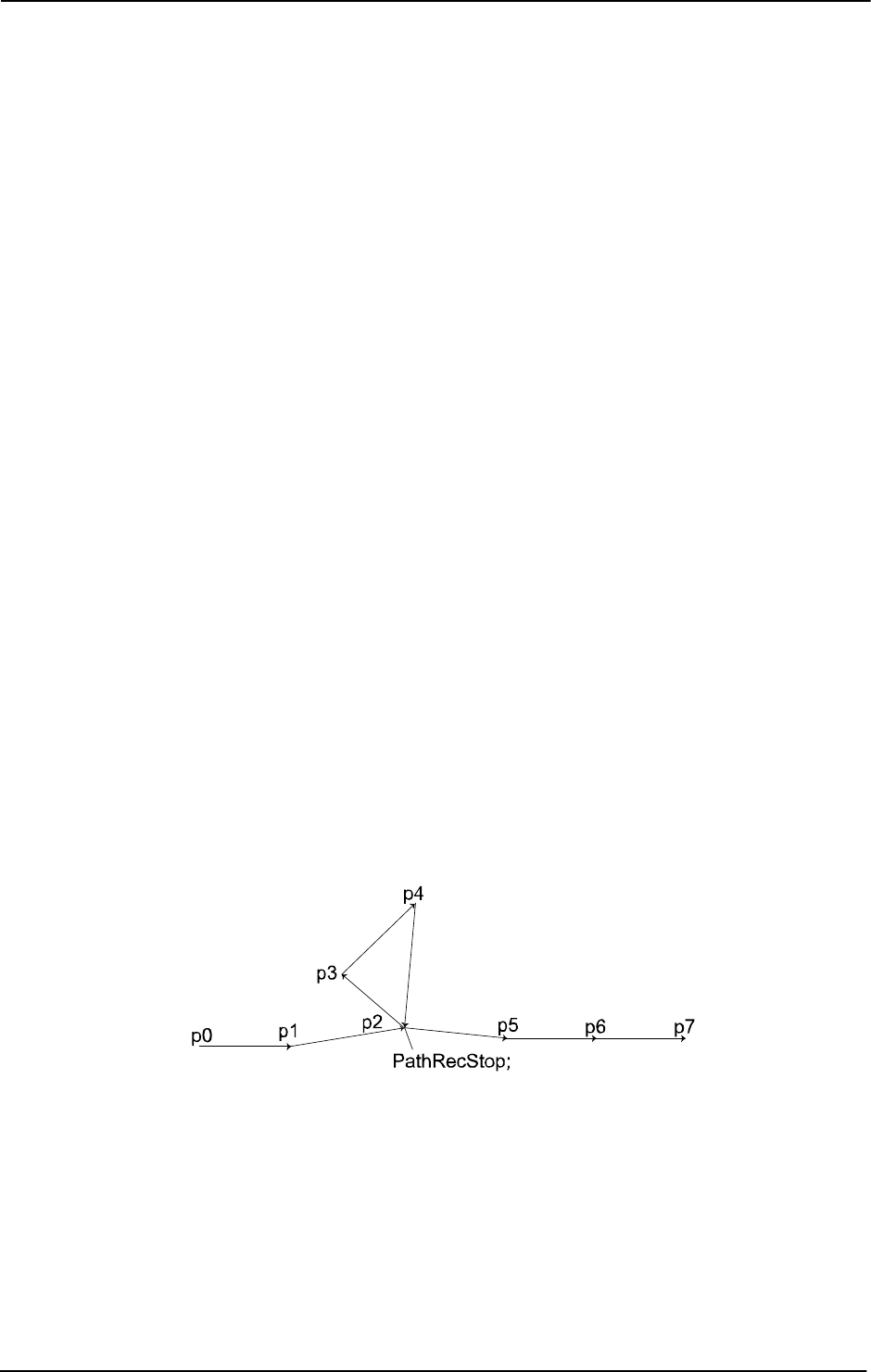
1 Instructions
1.111. PathRecStop - Stop the path recorder
Path Recovery
3HAC 16581-1 Revision: J312
© Copyright 2004-2010 ABB. All rights reserved.
MoveL p5, vmax, z50, tool1;
MoveL p6, vmax, z50, tool1;
StorePath;
PathRecMoveBwd \ID:=id1;
PathRecMoveFwd;
RestoPath;
StartMove;
MoveL p7, vmax, z50, tool1;
ENDPROC
PROC example2()
MoveL p0, vmax, z50, tool1;
PathRecStart id1;
MoveL p1, vmax, z50, tool1;
MoveL p2, vmax, z50, tool1;
PathRecStop;
MoveL p3, vmax, z50, tool1;
MoveL p4, vmax, z50, tool1;
PathRecStart id2;
MoveL p2, vmax, z50, tool1;
MoveL p5, vmax, z50, tool1;
MoveL p6, vmax, z50, tool1;
StorePath;
PathRecMoveBwd \ID:=id1;
PathRecMoveFwd;
RestoPath;
StartMove;
MoveL p7, vmax, z50, tool1;
ENDPROC
xx0500002101
The above examples describe recording of the robot path when the recording is stopped in the
middle of the sequence. In
example1 the PathRecMoveBwd \ID:=id1; order is valid and
the robot will execute the following path:
p6 -> p5 -> p2 -> p1 -> p0
The reason that the order is valid is due to the recorder being stopped and started in the exact
same robot position. If this behavior isn’t desirable the stop order should include the optional
argument
\Clear. In that way the recorded path will be cleared and it will never be possible
to back-up to previous path recorder identifiers.
Continued
Continues on next page

1 Instructions
1.111. PathRecStop - Stop the path recorder
Path Recovery
3133HAC 16581-1 Revision: J
© Copyright 2004-2010 ABB. All rights reserved.
The only difference in example2 is where the recorder was started the second time. In this
case
PathRecMoveBwd \ID:=id1 will cause an error. This is because no recorded path
exists between
p4, p3 and p2. However, it is possible to execute PathRecMoveBwd
\ID:=id2
.
Syntax
PathRecStop
[ ´\’switch Clear ] ´;’
Related information
For information about See
Path Recorder Identifiers pathrecid - Path recorder identifier on page 1158
Start the path recorder PathRecStart - Start the path recorder on page 308
Check for valid recorded path PathRecValidBwd - Is there a valid backward path
recorded on page 921
PathRecValidFwd - Is there a valid forward path
recorded on page 924
Play the recorder backward PathRecMoveBwd - Move path recorder
backwards on page 298
Play the recorder forwards PathRecMoveFwd - Move path recorder forward
on page 305
Motion in general Technical reference manual - RAPID overview,
section Motion and I/O principles
Continued

1 Instructions
1.112. PathResol - Override path resolution
RobotWare - OS
3HAC 16581-1 Revision: J314
© Copyright 2004-2010 ABB. All rights reserved.
1.112. PathResol - Override path resolution
Usage
PathResol (Path Resolution) is used to override the configured geometric path sample time
defined in the system parameters for the mechanical units that are controlled from current
program task.
This instruction can only be used in the main task
T_ROB1 or, if in a MultiMove system, in
any motion tasks.
Description
The path resolution affects the accuracy of the interpolated path and the program cycle time.
The path accuracy is improved and the cycle time is often reduced when the parameter
PathSampleTime is decreased. A value for parameter PathSampleTime, which is too low,
may cause CPU load problems in some demanding applications. However, use of the standard
configured path resolution (
PathSampleTime 100%) will avoid CPU load problems and
provide sufficient path accuracy in most situations.
Example of
PathResol usage:
Dynamically critical movements (max payload, high speed, combined joint motions close to
the border of the work area) may cause CPU load problems. Increase the parameter
PathSampleTime.
Low performance external axes may cause CPU load problems during coordination. Increase
the parameter
PathSampleTime.
Arc-welding with high frequency weaving may require high resolution of the interpolated
path. Decrease the parameter
PathSampleTime.
Small circles or combined small movements with direction changes can decrease the path
performance quality and increase the cycle time. Decrease the parameter
PathSampleTime.
Gluing with large reorientations and small corner zones can cause speed variations. Decrease
the parameter
PathSampleTime.
Basic examples
Basic examples of the instruction
PathResol are illustrated below.
MoveJ p1,v1000,fine,tool1;
PathResol 150;
With the robot at a stop point the path sample time is increased to 150 % of the configured.
Arguments
PathResol PathSampleTime
PathSampleTime
Data type: num
Override as a percent of the configured path sample time. 100% corresponds to the configured
path sample time. Within the range 25-400%.
A lower value of the parameter
PathSampleTime improves the path resolution (path
accuracy).
Continues on next page

1 Instructions
1.112. PathResol - Override path resolution
RobotWare - OS
3153HAC 16581-1 Revision: J
© Copyright 2004-2010 ABB. All rights reserved.
Program execution
The path resolutions of all subsequent positioning instructions are affected until a new
PathResol instruction is executed. This will affect the path resolution during all program
execution of movements (default path level and path level after
StorePath) and also during
jogging.
In a MultiMove system at synchronized coordinated mode the following points are valid:
• All mechanical units involved in synchronized coordinated mode will run with the
current path resolution for actual (used) motion planner.
• New path resolution order against actual motion planner affects the synchronized
coordinated movement and future independent movement in that motion planner.
• New path resolution order against another motion planner only affects future
independent movement in that motion planner.
About connection between program task and motion planner see Application manual -
MultiMove.
The default value for override of path sample time is 100%. This value is automatically set
• at a cold start-up.
• when a new program is loaded.
• when starting program execution from the beginning.
The current override of path sample time can be read from the variable
C_MOTSET (data type
motsetdata) in the component pathresol.
Limitation
If this instruction is preceded by a move instruction then that move instruction must be
programmed with a stop point (zonedata
fine), not a fly-by point. Otherwise restart after
power failure will not be possible.
PathResol cannot be executed in a RAPID routine connected to any of following special
system events: PowerOn, Stop, QStop, Restart, or Step.
Syntax
PathResol
[PathSampleTime ’:=’ ] < expression (IN) of num> ’;’
Related information
For information about See
Positioning instructions Technical reference manual - RAPID overview, section
Motion and I/O principles
Motion settings Technical reference manual - RAPID overview, section
RAPID summary - Motion settings
Configuration of path resolution Technical reference manual - System parameters,
section Motion Planner - CPU Load Equalization
Continued

1 Instructions
1.113. PDispOff - Deactivates program displacement
RobotWare - OS
3HAC 16581-1 Revision: J316
© Copyright 2004-2010 ABB. All rights reserved.
1.113. PDispOff - Deactivates program displacement
Usage
PDispOff (Program Displacement Off) is used to deactivate a program displacement.
Program displacement is activated by the instruction
PDispSet or PDispOn and applies to
all movements until some other program displacement is activated or until program
displacement is deactivated.
This instruction can only be used in the main task
T_ROB1 or, if in a MultiMove system, in
Motion tasks.
Basic examples
Basic examples of the instruction
PDispOff are illustrated below.
Example 1
PDispOff;
Deactivation of a program displacement.
Example 2
MoveL p10, v500, z10, tool1;
PDispOn \ExeP:=p10, p11, tool1;
MoveL p20, v500, z10, tool1;
MoveL p30, v500, z10, tool1;
PDispOff;
MoveL p40, v500, z10, tool1;
A program displacement is defined as the difference between the positions p10 and p11. This
displacement affects the movement to
p20 and p30 but not to p40.
Program execution
Active program displacement is reset. This means that the program displacement coordinate
system is the same as the object coordinate system, and thus all programmed positions will
be related to the latter.
Syntax
PDispOff ´;’
Related information
For information about See
Definition of program displacement using
two positions
PDispOn - Activates program displacement on
page 317
Definition of program displacement using
known frame
PDispSet - Activates program displacement
using known frame on page 321

1 Instructions
1.114. PDispOn - Activates program displacement
RobotWare - OS
3173HAC 16581-1 Revision: J
© Copyright 2004-2010 ABB. All rights reserved.
1.114. PDispOn - Activates program displacement
Usage
PDispOn (Program Displacement On) is used to define and activate a program displacement
using two robot positions.
Program displacement is used, for example, after a search has been carried out or when
similar motion patterns are repeated at several different places in the program.
This instruction can only be used in the main task
T_ROB1 or, if in a MultiMove system, in
Motion tasks.
Basic examples
Basic examples of the instruction
PDispOn are illustrated below.
See also More examples on page 319.
Example 1
MoveL p10, v500, z10, tool1;
PDispOn \ExeP:=p10, p20, tool1;
Activation of a program displacement (parallel displacement). This is calculated based on the
difference between positions
p10 and p20.
Example 2
MoveL p10, v500, fine \Inpos := inpos50, tool1;
PDispOn *, tool1;
Activation of a program displacement (parallel displacement). Since a stop point that is
accurately defined has been used in the previous instruction the argument
\ExeP does not
have to be used. The displacement is calculated on the basis of the difference between the
robot’s actual position and the programmed point (*) stored in the instruction.
Example 3
PDispOn \Rot \ExeP:=p10, p20, tool1;
Activation of a program displacement including a rotation. This is calculated based on the
difference between positions
p10 and p20.
Arguments
PDispOn [\Rot] [\ExeP] ProgPoint Tool [\WObj]
[ \Rot ]
Rotation
Data type:
switch
The difference in the tool orientation is taken into consideration and this involves a rotation
of the program.
[ \ExeP ]
Executed Point
Data type:
robtarget
The new robot position used for calculation of the displacement. If this argument is omitted
then the robot’s current position at the time of the program execution is used.
Continues on next page
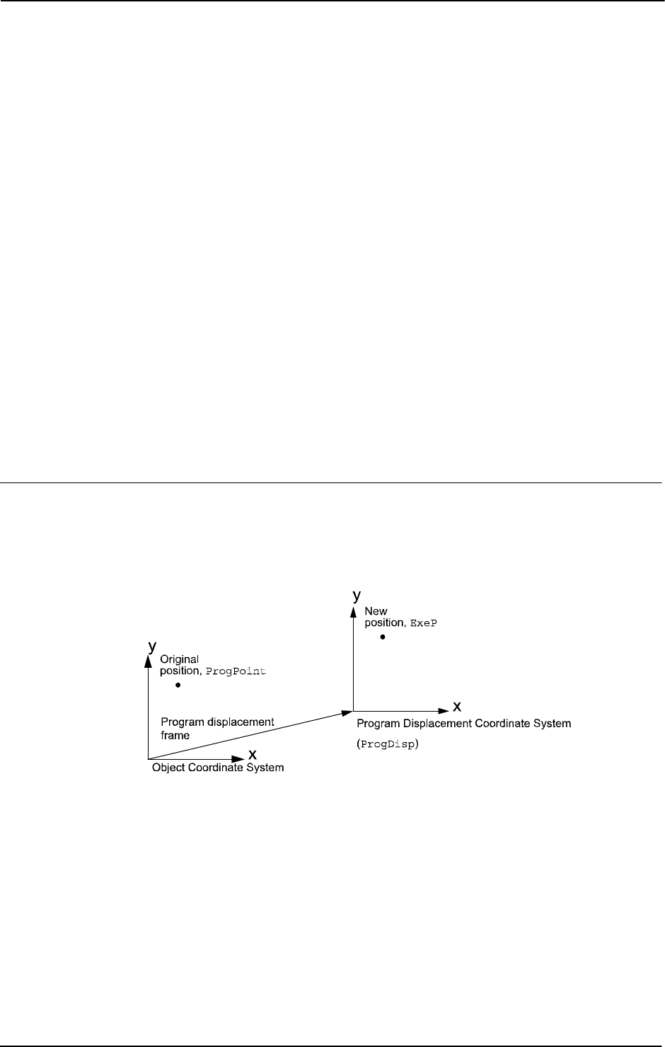
1 Instructions
1.114. PDispOn - Activates program displacement
RobotWare - OS
3HAC 16581-1 Revision: J318
© Copyright 2004-2010 ABB. All rights reserved.
ProgPoint
Programmed Point
Data type:
robtarget
The robot’s original position at the time of programming.
Tool
Data type: tooldata
The tool used during programming, i.e. the TCP to which the ProgPoint position is related.
[ \WObj ]
Work Object
Data type:
wobjdata
The work object (coordinate system) to which the ProgPoint position is related.
This argument can be omitted and if so then the position is related to the world coordinate
system. However, if a stationary TCP or coordinated external axes are used then this
argument must be specified.
The arguments Tool and \WObj are used both to calculate the
ProgPoint during
programming and to calculate the current position during program execution if no
\ExeP
argument is programmed.
Program execution
Program displacement means that the
ProgDisp coordinate system is translated in relation
to the object coordinate system. Since all positions are related to the
ProgDisp coordinate
system, all programmed positions will also be displaced. See figure below, which shows
parallel displacement of a programmed position using program displacement.
xx0500002186
Program displacement is activated when the instruction PDispOn is executed and remains
active until some other program displacement is activated (the instruction
PDispSet or
PDispOn) or until program displacement is deactivated (the instruction PDispOff).
Only one program displacement can be active at the same time. Several
PDispOn
instructions, on the other hand, can be programmed one after the other and in this case the
different program displacements will be added.
Program displacement is calculated as the difference between
ExeP and ProgPoint. If ExeP
has not been specified then the current position of the robot at the time of the program
execution is used instead. Since it is the actual position of the robot that is used, the robot
should not move when
PDispOn is executed.
Continued
Continues on next page
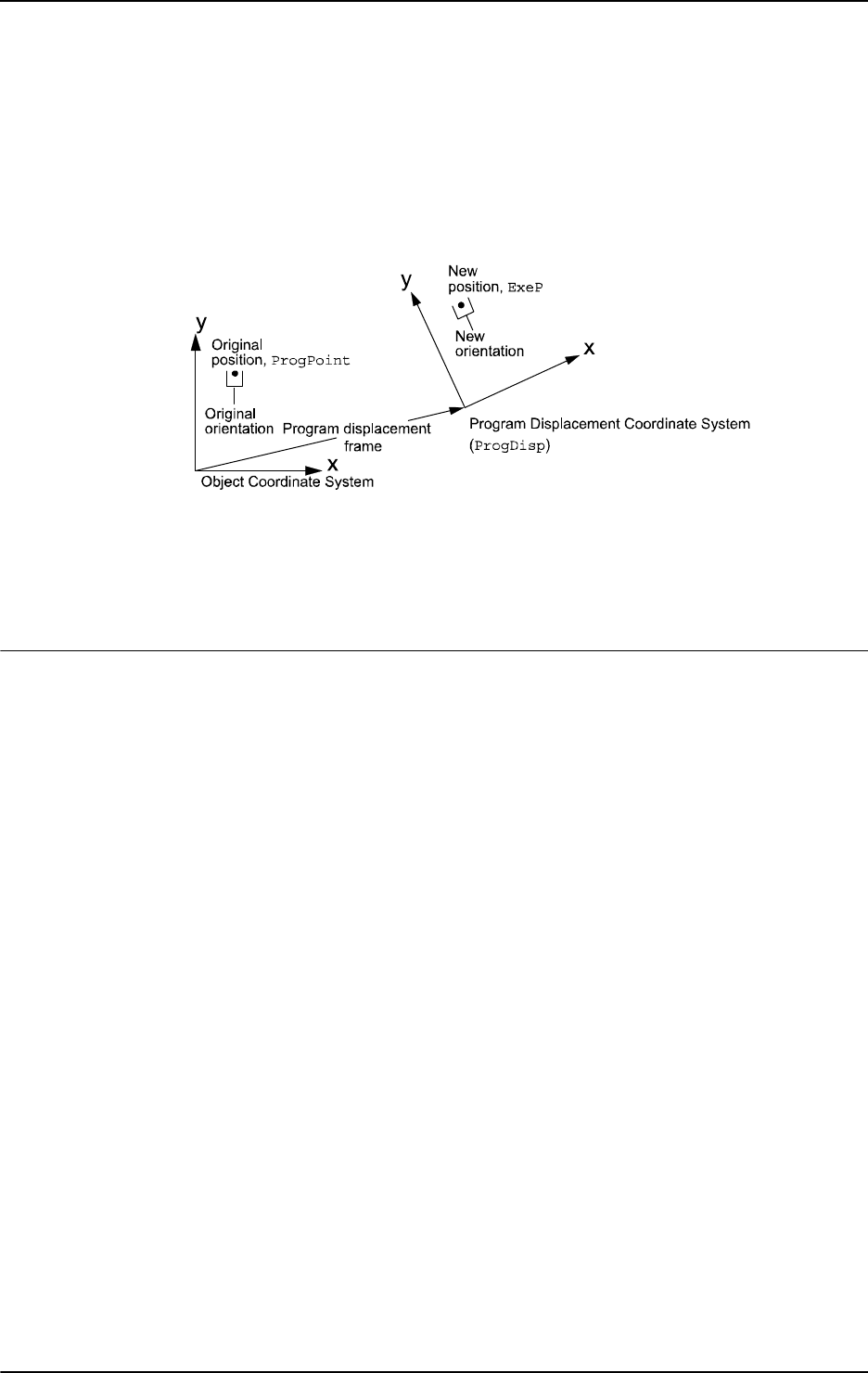
1 Instructions
1.114. PDispOn - Activates program displacement
RobotWare - OS
3193HAC 16581-1 Revision: J
© Copyright 2004-2010 ABB. All rights reserved.
If the argument \Rot is used then the rotation is also calculated based on the tool orientation
at the two positions. The displacement will be calculated in such a way that the new position
(
ExeP) will have the same position and orientation in relation to the displaced coordinate
system,
ProgDisp, as the old position (ProgPoint) had in relation to the original object
coordinate system. See the figure below, which shows translation and rotation of a
programmed position.
xx0500002187
The program displacement is automatically reset
• at a cold start-up.
• when a new program is loaded.
• when starting program execution from the beginning.
More examples
More examples of how to use the instruction
PDispOn are illustrated below.
Example 1
PROC draw_square()
PDispOn *, tool1;
MoveL *, v500, z10, tool1;
MoveL *, v500, z10, tool1;
MoveL *, v500, z10, tool1;
MoveL *, v500, z10, tool1;
PDispOff;
ENDPROC
...
MoveL p10, v500, fine \Inpos := inpos50, tool1;
draw_square;
MoveL p20, v500, fine \Inpos := inpos50, tool1;
draw_square;
MoveL p30, v500, fine \Inpos := inpos50, tool1;
draw_square;
Continued
Continues on next page

1 Instructions
1.114. PDispOn - Activates program displacement
RobotWare - OS
3HAC 16581-1 Revision: J320
© Copyright 2004-2010 ABB. All rights reserved.
The routine draw_square is used to execute the same motion pattern at three different
positions based on the positions
p10, p20, and p30. See the figure below, which shows that
when using program displacement the motion patterns can be reused.
xx0500002185
Example 2
SearchL sen1, psearch, p10, v100, tool1\WObj:=fixture1;
PDispOn \ExeP:=psearch, *, tool1 \WObj:=fixture1;
A search is carried out in which the robot’s searched position is stored in the position
psearch. Any movement carried out after this starts from this position using a program
displacement (parallel displacement). The latter is calculated based on the difference between
the searched position and the programmed point (
*) stored in the instruction. All positions are
based on the
fixture1 object coordinate system.
Syntax
PDispOn
[ [ ’\’ Rot ]
[’\’ ExeP ’:=’ < expression (IN) of robtarget>]’,’]
[ ProgPoint’ :=’ ] < expression (IN) of robtarget> ’,’
[ Tool ’:=’ ] < persistent (PERS) of tooldata>
[ ´\’WObj’ :=’ < persistent (PERS) of wobjdata> ] ´;’
Related information
For information about See
Deactivation of program displacement PDispOff - Deactivates program displacement
on page 316
Definition of program displacement using
known frame
PDispSet - Activates program displacement
using known frame on page 321
Coordinate systems Technical reference manual - System
parameters, section Motion and I/O principles -
Coordinate systems
Definition of tools tooldata - Tool data on page 1207
Definition of work objects wobjdata - Work object data on page 1224
Continued
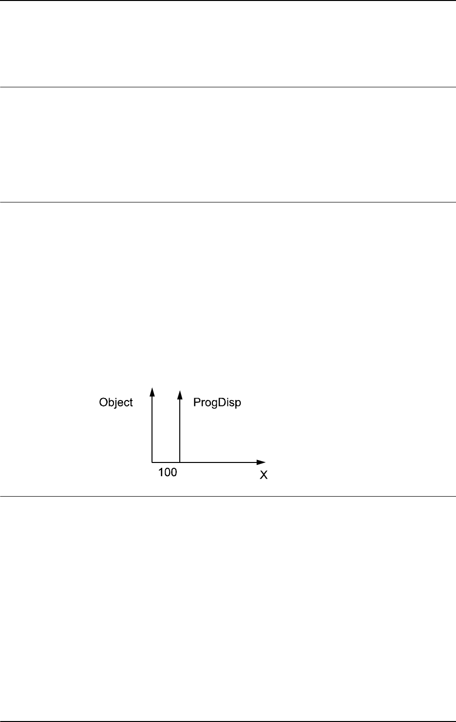
1 Instructions
1.115. PDispSet - Activates program displacement using known frame
RobotWare - OS
3213HAC 16581-1 Revision: J
© Copyright 2004-2010 ABB. All rights reserved.
1.115. PDispSet - Activates program displacement using known frame
Usage
PDispSet (Program Displacement Set) is used to define and activate a program
displacement using known frame.
Program displacement is used, for example, when similar motion patterns are repeated at
several different places in the program.
This instruction can only be used in the main task
T_ROB1 or, if in a MultiMove system, in
Motion tasks.
Basic examples
Basic examples of the instruction
PDispSet are illustrated below.
Example 1
VAR pose xp100 := [ [100, 0, 0], [1, 0, 0, 0] ];
...
PDispSet xp100;
Activation of the xp100 program displacement meaning that:
• The ProgDisp coordinate system is displaced 100 mm from the object coordinate
system in the direction of the positive x-axis (see figure below).
• As long as this program displacement is active all positions will be displaced 100 mm
in the direction of the x-axis.
The figure shows a 100 mm program displacement along the x-axis.
xx0500002199
Arguments
PDispSet DispFrame
DispFrame
Displacement Frame
Datatype:
pose
The program displacement is defined as data of the type pose.
Continues on next page
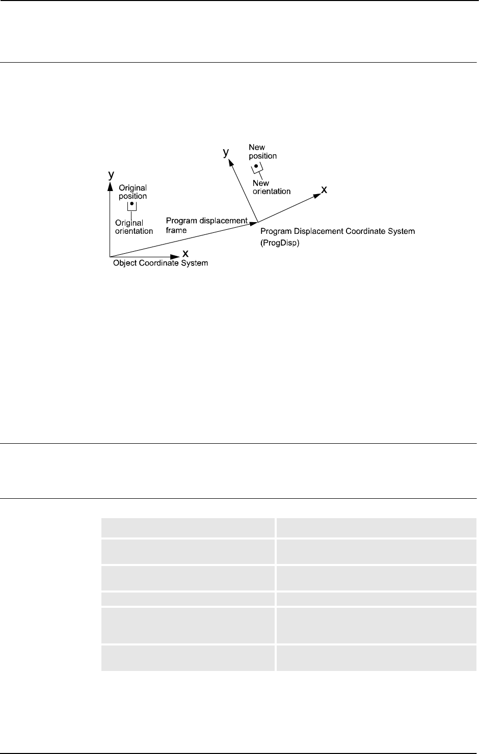
1 Instructions
1.115. PDispSet - Activates program displacement using known frame
RobotWare - OS
3HAC 16581-1 Revision: J322
© Copyright 2004-2010 ABB. All rights reserved.
Program execution
Program displacement involves translating and/or rotating the
ProgDisp coordinate system
relative to the object coordinate system. Since all positions are related to the
ProgDisp
coordinate system, all programmed positions will also be displaced. See the figure below,
which shows translation and rotation of a programmed position.
xx0500002204
Program displacement is activated when the instruction PDispSet is executed and remains
active until some other program displacement is activated (the instruction
PDispSet or
PDispOn) or until program displacement is deactivated (the instruction PDispOff).
Only one program displacement can be active at the same time. Program displacements
cannot be added to one another using
PDispSet.
The program displacement is automatically reset
• at a cold start-up.
• when a new program is loaded.
• when starting program execution from the beginning.
Syntax
PDispSet
[ DispFrame ’:=’ ] < expression (IN) of pose> ’;’
Related information
For information about See
Deactivation of program displacement PDispOff - Deactivates program displacement
on page 316
Definition of program displacement using
two positions
PDispOn - Activates program displacement on
page 317
Definition of data of the type pose pose - Coordinate transformations on page 1162
Coordinate systems Technical reference manual - RAPID overview,
section Motion and I/O principles - Coordinate
systems
Examples of how program displacement
can be used
PDispOn - Activates program displacement on
page 317
Continued

1 Instructions
1.116. ProcCall - Calls a new procedure
RobotWare - OS
3233HAC 16581-1 Revision: J
© Copyright 2004-2010 ABB. All rights reserved.
1.116. ProcCall - Calls a new procedure
Usage
A procedure call is used to transfer program execution to another procedure. When the
procedure has been fully executed the program execution continues with the instruction
following the procedure call.
It is usually possible to send a number of arguments to the new procedure. These control the
behavior of the procedure and make it possible for the same procedure to be used for different
things.
Basic examples
Basic examples of the instruction
ProcCall are illustrated below.
Example 1
weldpipe1;
Calls the weldpipe1 procedure.
Example 2
errormessage;
Set do1;
...
PROC errormessage()
TPWrite "ERROR";
ENDPROC
The errormessage procedure is called. When this procedure is ready the program
execution returns to the instruction following the procedure call,
Set do1.
Arguments
Procedure { Argument }
Procedure
Identifier
The name of the procedure to be called.
Argument
Data type: In accordance with the procedure declaration.
The procedure arguments (in accordance with the parameters of the procedure).
Basic examples
Basic examples of the instruction
ProcCall are illustrated below.
Example 1
weldpipe2 10, lowspeed;
Calls the weldpipe2 procedure including two arguments.
Example 2
weldpipe3 10 \speed:=20;
Calls the weldpipe3 procedure including one mandatory and one optional argument.
Continues on next page

1 Instructions
1.116. ProcCall - Calls a new procedure
RobotWare - OS
3HAC 16581-1 Revision: J324
© Copyright 2004-2010 ABB. All rights reserved.
Limitations
The procedure’s arguments must agree with its parameters:
• All mandatory arguments must be included.
• They must be placed in the same order.
• They must be of the same data type.
• They must be of the correct type with respect to the access-mode (input, variable, or
persistent).
A routine can call a routine which, in turn, calls another routine, etc. A routine can also call
itself, i.e. a recursive call. The number of routine levels permitted depends on the number of
parameters. More than 10 levels are usually permitted.
Syntax
(EBNF)
<procedure> [ <argument list> ] ’;’
<procedure> ::= <identifier>
Related information
For information about See
Arguments, parameters Technical reference manual - RAPID overview,
section Basic characteristics - Routines
Continued

1 Instructions
1.117. ProcerrRecovery - Generate and recover from process-move error
RobotWare - OS
3253HAC 16581-1 Revision: J
© Copyright 2004-2010 ABB. All rights reserved.
1.117. ProcerrRecovery - Generate and recover from process-move error
Usage
ProcerrRecovery can be used to generate process error during robot movement and get the
possibility to handle the error and restart the process and the movement from an ERROR
handler.
Basic examples
Basic examples of the instruction
ProcerrRecovery are illustrated below.
See also More examples on page 327.
The examples below are not realistic but are shown for pedagogic reasons.
Example 1
MoveL p1, v50, z30, tool2;
ProcerrRecovery \SyncOrgMoveInst;
MoveL p2, v50, z30, tool2;
ERROR
IF ERRNO = ERR_PATH_STOP THEN
StartMove;
RETRY;
ENDIF
The robot movement stops on its way to p1 and the program execution transfers to the ERROR
handler in the routine that created the actual path on which the error occurred, in this case the
path to
MoveL p1. The movement is restarted with StartMove and the execution is
continued with
RETRY.
Example 2
MoveL p1, v50, fine, tool2;
ProcerrRecovery \SyncLastMoveInst;
MoveL p2, v50, z30, tool2;
ERROR
IF ERRNO = ERR_PATH_STOP THEN
StartMove;
RETRY;
ENDIF
The robot movement stops at once on its way to p2. The program execution transfers to the
ERROR handler in the routine where the program is currently executing or is going to execute
a move instruction when the error occurred, in this case
MoveL p2. The movement is
restarted with
StartMove and the execution is continued with RETRY.
Continues on next page

1 Instructions
1.117. ProcerrRecovery - Generate and recover from process-move error
RobotWare - OS
3HAC 16581-1 Revision: J326
© Copyright 2004-2010 ABB. All rights reserved.
Arguments
ProcerrRecovery[\SyncOrgMoveInst] | [\SyncLastMoveInst]
[\ProcSignal]
[\SyncOrgMoveInst]
Data type: switch
The error can be handled in the routine that created the actual path on which the error
occurred.
[\SyncLastMoveInst]
Data type: switch
The error can be handled in the routine where the program is currently executing a move
instruction when the error occurred.
If the program is currently not executing a move instruction when the error occurred then the
transfer of the execution to the
ERROR handler will be delayed until the program executes the
next move instruction. This means that the transfer to the
ERROR handler will be delayed if
the robot is in a stop point or between the prefetch point and the middle of the corner path.
The error can be handled in that routine.
[\ProcSignal]
Data type: signaldo
Optional parameter that let the user turn on/off the use of the instruction. If this parameter is
used and the signal value is 0, an recoverable error will be thrown, and no process error will
be generated.
Program execution
Execution of
ProcerrRecovery in continuous mode results in the following:
• At once the robot is stopped on its path.
• The variable ERRNO is set to ERR_PATH_STOP.
• The execution is transferred to some ERROR handler according the rules for
asynchronously raised errors.
This instruction does nothing in any step mode.
For description of asynchronously raised errors that are generated with
ProcerrRecovery
see RAPID kernel reference/Error recovery/Asynchronously raised errors.
ProcerrRecovery can also be used in MultiMove system to transfer the execution to the
ERROR handler in several program tasks if running in synchronized mode.
Continued
Continues on next page

1 Instructions
1.117. ProcerrRecovery - Generate and recover from process-move error
RobotWare - OS
3273HAC 16581-1 Revision: J
© Copyright 2004-2010 ABB. All rights reserved.
More examples
More examples of how to use the instruction
ProcerrRecovery are illustrated below.
Example with ProcerrRecovery\SyncOrgMoveInst
MODULE user_module
VAR intnum proc_sup_int;
PROC main()
...
MoveL p1, v1000, fine, tool1;
do_process;
...
ENDPROC
PROC do_process()
my_proc_on;
MoveL p2, v200, z10, tool1;
MoveL p3, v200, fine, tool1;
my_proc_off;
ERROR
IF ERRNO = ERR_PATH_STOP THEN
my_proc_on;
StartMove;
RETRY;
ENDIF
ENDPROC
TRAP iprocfail
my_proc_off;
ProcerrRecovery \SyncOrgMoveInst;
ENDTRAP
PROC my_proc_on()
SetDO do_myproc, 1;
CONNECT proc_sup_int WITH iprocfail;
ISignalDI di_proc_sup, 1, proc_sup_int;
ENDPROC
PROC my_proc_off()
SetDO do_myproc, 0;
IDelete proc_sup_int;
ENDPROC
ENDMODULE
Continued
Continues on next page

1 Instructions
1.117. ProcerrRecovery - Generate and recover from process-move error
RobotWare - OS
3HAC 16581-1 Revision: J328
© Copyright 2004-2010 ABB. All rights reserved.
Asynchronously raised errors generated by ProcerrRecovery with switch
\
SyncOrgMoveInst can, in this example, be treated in the routine do_process because the
path on which the error occurred is always created in the routine d
o_process.
A process flow is started by setting the signal
do_myproc to 1. The signal di_proc_sup
supervise the process, and an asynchronous error is raised if
di_proc_sup becomes 1. In
this simple example the error is resolved by setting
do_myproc to 1 again before resuming
the movement.
Example with ProcerrRecovery\SyncLastMoveInst
MODULE user_module
PROC main()
...
MoveL p1, v1000, fine, tool1;
do_process;
...
ENDPROC
PROC do_process()
proc_on;
proc_move p2, v200, z10, tool1;
proc_move p3, v200, fine, tool1;
proc_off;
ERROR
IF ERRNO = ERR_PATH_STOP THEN
StorePath;
p4 := CRobT(\Tool:=tool1);
! Move to service station and fix the problem
MoveL p4, v200, fine, tool1;
RestoPath;
proc_on;
StartMoveRetry;
ENDIF
ENDPROC
ENDMODULE
MODULE proc_module (SYSMODULE, NOSTEPIN)
VAR intnum proc_sup_int;
VAR num try_no := 0;
TRAP iprocfail
proc_off;
ProcerrRecovery \SyncLastMoveInst;
ENDTRAP
Continued
Continues on next page

1 Instructions
1.117. ProcerrRecovery - Generate and recover from process-move error
RobotWare - OS
3293HAC 16581-1 Revision: J
© Copyright 2004-2010 ABB. All rights reserved.
PROC proc_on()
SetDO do_proc, 1;
CONNECT proc_sup_int WITH iprocfail;
ISignalDI di_proc_sup, 1, proc_sup_int;
ENDPROC
PROC proc_off()
SetDO do_proc, 0;
IDelete proc_sup_int;
ENDPROC
PROC proc_move (robtarget ToPoint, speeddata Speed, zonedata Zone,
PERS tooldata Tool)
MoveL ToPoint, Speed, Zone, Tool;
ERROR
IF ERRNO = ERR_PATH_STOP THEN
try_no := try_no + 1;
IF try_no < 4 THEN
proc_on;
StartMoveRetry;
ELSE
RaiseToUser \Continue;
ENDIF
ENDPROC
ENDMODULE
Asynchronously raised errors generated by ProcerrRecovery with switch
\SyncLastMoveInst can in this example be treated in the routine proc_move because all
move instructions are always created in the routine proc_move. When program pointer is in
routine
do_process the transfer to ERROR handler will be delayed until running the next
MoveL in routine proc_move. Note that the movements are always stopped at once.
A process flow is started by setting the signal
do_myproc to 1. The signal di_proc_sup
supervise the process, and an asynchronous error is raised if
di_proc_sup becomes 1. In
this simple example the error is resolved by setting
do_myproc to 1 again before resuming
the movement.
When using predefined
NOSTEPIN routine we recommend using the option switch parameter
\
SyncLastMoveInst because then the predefined routine can make the decision to handle
some error situation within the routine while others must be handled by the end user.
Error handling
Following recoverable errors can be generated. The errors can be handled in an error handler.
If the optional parameter
\ProcSignal is used and if the signal is off when the instruction
is executed, the system variable
ERRNO is set to ERR_PROCSIGNAL_OFF and the execution
continues in the error handler.
If there is no contact with the I/O unit, the system variable
ERRNO is set to ERR_NORUNUNIT
and the execution continues in the error handler.
Continued
Continues on next page

1 Instructions
1.117. ProcerrRecovery - Generate and recover from process-move error
RobotWare - OS
3HAC 16581-1 Revision: J330
© Copyright 2004-2010 ABB. All rights reserved.
Limitations
Error recovery from asynchronously raised process errors can only be done if the motion task
with the process move instruction is executing on base level when the process error occurs.
So error recovery can not be done if the program task with the process instruction executes in:
• any event routine
• any routine handler (ERROR, BACKWARD or UNDO)
• user execution level (service routine)
See RAPID reference manual - RAPID kernel, Error recovery, Asynchronously raised errors.
If no error handler with a
StartMove + RETRY or a StartMoveRetry is used, the program
execcution will hang. The only way to reset this is to do a PP to main.
Syntax
ProcerrRecovery
[ ’\’ SyncOrgMoveInst ] | [’ \’ SyncLastMoveInst ]
[ ’\’ ProcSignal’ :=’ ] < variable (VAR) of signaldo > ’;’
Related information
For information about See
Error handlers Technical reference manual - RAPID overview,
section Basic Characteristics - Error Recovery
Asynchronously raised errors RAPID reference manual - RAPID kernel - Error
recover
Propagates an error to user level RaiseToUser - Propagates an error to user level
on page 337
Resume movement and program
execution
StartMoveRetry - Restarts robot movement and
execution on page 489
Continued

1 Instructions
1.118. PulseDO - Generates a pulse on a digital output signal
RobotWare - OS
3313HAC 16581-1 Revision: J
© Copyright 2004-2010 ABB. All rights reserved.
1.118. PulseDO - Generates a pulse on a digital output signal
Usage
PulseDO is used to generate a pulse on a digital output signal.
Basic examples
Basic examples of the instruction
PulseDO are illustrated below.
Example 1
PulseDO do15;
A pulse with a pulse length of 0.2 s is generated on the output signal do15.
Example 2
PulseDO \PLength:=1.0, ignition;
A pulse of length 1.0 s is generated on the signal ignition.
Example 3
! Program task MAIN
PulseDO \High, do3;
! At almost the same time in program task BCK1
PulseDO \High, do3;
Positive pulse (value 1) is generated on the signal do3 from two program tasks at almost the
same time. It will result in one positive pulse with a pulse length longer than the default 0.2
s or two positive pulses after each other with a pulse length of 0.2 s.
Arguments
PulseDO [ \High ] [ \PLength ] Signal
[ \High ]
High level
Data type:
switch
Specifies that the signal value should always be set to high (value 1) when the instruction is
executed independently of its current state.
[ \PLength ]
Pulse Length
Data type:
num
The length of the pulse in seconds (0.001 - 2000 s). If the argument is omitted a 0.2 second
pulse is generated.
Signal
Data type: signaldo
The name of the signal on which a pulse is to be generated.
Continues on next page
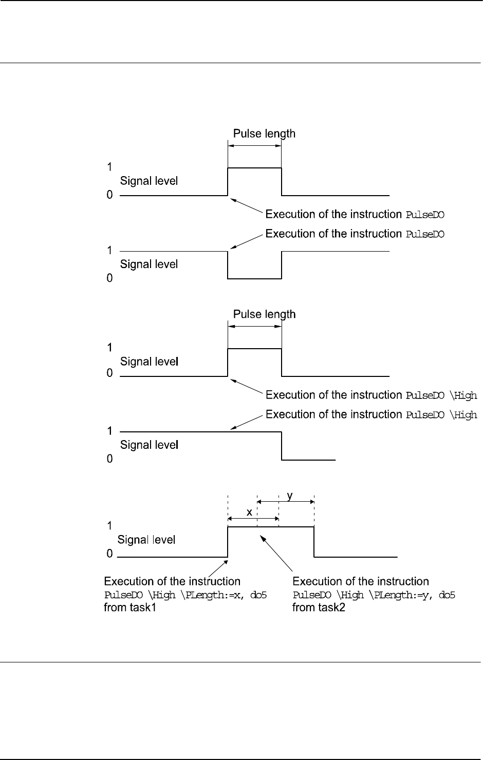
1 Instructions
1.118. PulseDO - Generates a pulse on a digital output signal
RobotWare - OS
3HAC 16581-1 Revision: J332
© Copyright 2004-2010 ABB. All rights reserved.
Program execution
The next instruction after
PulseDO is executed directly after the pulse starts. The pulse can
then be set/reset without affecting the rest of the program execution.
The figure below shows examples of generation of pulses on a digital output signal.
xx0500002217
The next instruction is executed directly after the pulse starts. The pulse can then be set/reset
without affecting the rest of the program execution.
Limitations
The length of the pulse has a resolution off 0.001 seconds. Programmed values that differ
from this are rounded off.
Continued
Continues on next page

1 Instructions
1.118. PulseDO - Generates a pulse on a digital output signal
RobotWare - OS
3333HAC 16581-1 Revision: J
© Copyright 2004-2010 ABB. All rights reserved.
Error handling
Following a recoverable error can be generated. The error can be handled in an error handler.
The system variable
ERRNO will be set to:
ERR_NORUNUNIT
if there is no contact with the unit.
Syntax
PulseDO
[ ’\’High]
[ ’\’PLength’ :=’ < expression (IN) of num >] ´,’
[ Signal ’:=’ ] < variable (VAR) of signaldo > ’;’
Related information
For information about See
Input/Output instructions Technical reference manual - RAPID overview,
section RAPID summary - Input and output signals
Input/Output functionality in general Technical reference manual - RAPID overview,
section Motion and I/O principles - I/O principles
Configuration of I/O Technical reference manual - System parameters
Continued

1 Instructions
1.119. RAISE - Calls an error handler
RobotWare-OS
3HAC 16581-1 Revision: J334
© Copyright 2004-2010 ABB. All rights reserved.
1.119. RAISE - Calls an error handler
Usage
RAISE is used to create an error in the program and then to call the error handler of the
routine.
RAISE can also be used in the error handler to propagate the current error to the error handler
of the calling routine.
This instruction can, for example, be used to jump back to a higher level in the structure of
the program, e.g. to the error handler in the main routine if an error occurs at a lower level.
Basic examples
Basic examples of the instruction RAISE are illustrated below.
See also More examples on page 335.
Example 1
MODULE MainModule .
VAR errnum ERR_MY_ERR := -1;
PROC main()
BookErrNo ERR_MY_ERR;
IF di1 = 0 THEN
RAISE ERR_MY_ERR;
ENDIF
ERROR
IF ERRNO = ERR_MY_ERR THEN
TPWrite "di1 equals 0";
ENDIF
ENDPROC
ENDMODULE
For this implementation di1 equals 0 is regarded as an error. RAISE will force the execution
to the error handler. In this example the user has created his own error number to handle the
specific error.
BookErrNo belongs to the base functionality Advanced RAPID.
Continues on next page

1 Instructions
1.119. RAISE - Calls an error handler
RobotWare-OS
3353HAC 16581-1 Revision: J
© Copyright 2004-2010 ABB. All rights reserved.
Arguments
RAISE [ Error no. ]
Error no.
Data type: errnum
Error number: Any number between 1 and 90 which the error handler can use to locate the
error that has occurred (the
ERRNO system variable).
It is also possible to book an error number outside the range 1-90 with the instruction
BookErrNo.
The error number must be specified outside the error handler in a RAISE instruction in order
to be able to transfer execution to the error handler of that routine.
If the instruction is present in a routine’s error handler then the error is propagated to the error
handler of the calling routine. In this case the error number does not have to be specified.
More examples
More examples of the instruction RAISE are illustrated below.
Example 1
MODULE MainModule
VAR num value1 := 10;
VAR num value2 := 0;
PROC main()
routine1;
ERROR
IF ERRNO = ERR_DIVZERO THEN
value2 := 1;
RETRY;
ENDIF
ENDPROC
PROC routine1()
value1 := 5/value2;!This will lead to an error when value2 is
equal to 0.
ERROR
RAISE;
ENDPROC
ENDMODULE
In this example the division with zero will result in an error. In the ERROR-handler RAISE will
propagate the error to the ERROR-handler in the calling routine "main". The same error
number remains active.
RETRY will re-run the whole routine "routine1".
Continued
Continues on next page

1 Instructions
1.119. RAISE - Calls an error handler
RobotWare-OS
3HAC 16581-1 Revision: J336
© Copyright 2004-2010 ABB. All rights reserved.
Program execution
Program execution continues in the routine’s error handler. After the error handler has been
executed the program execution can continue with:
• the routine that called the routine in question (RETURN).
• the error handler of the routine that called the routine in question (RAISE).
A RAISE instruction in a routine’s error handler also has another feature. It can be used for
long jump (see“ Error Recovery With Long Jump”). With a long jump it is possible to
propagate an error from an error handler from a deep nested call chain to a higher level in one
step.
If the RAISE instruction is present in a trap routine, the error is dealt with by the system’s
error handler.
Error handling
If the error number is out of range then the system variable ERRNO is set to ERR_ILLRAISE
(see "Data types - errnum"). This error can be handled in the error handler.
Syntax
(EBNF)
RAISE [<error number>] ’;’
<error number> ::= <expression>
Related information
For information about See
Error handling Technical reference manual - System parameters,
section Basic Characteristics - Error Recovery
Error recovery with long jump Technical reference manual - System parameters,
section Basic Characteristics - Error Recovery
Booking error numbers BookErrNo - Book a RAPID system error number
on page 30
Continued

1 Instructions
1.120. RaiseToUser - Propagates an error to user level
RobotWare - OS
3373HAC 16581-1 Revision: J
© Copyright 2004-2010 ABB. All rights reserved.
1.120. RaiseToUser - Propagates an error to user level
Usage
RaiseToUser is used in an error handler in nostepin routines to propagate the current error
or any other defined error to the error handler at user level. User level is in this case the first
routine in a call chain above a nostepin routine.
Basic examples
Basic examples of the instruction RaiseToUser are illustrated below.
Example 1
MODULE MyModule
VAR errnum ERR_MYDIVZERO:= -1;
PROC main()
BookErrNo ERR_MYDIVZERO;
...
routine1;
...
ERROR
IF ERRNO = ERR_MYDIVZERO THEN
TRYNEXT;
ELSE
RETRY;
ENDIF
ENDPROC
ENDMODULE
MODULE MySysModule (SYSMODULE, NOSTEPIN, VIEWONLY)
PROC routine1()
...
routine2;
...
UNDO
! Free allocated resources
ENDPROC
PROC routine2()
VAR num n:=0;
...
reg1:=reg2/n;
...
ERROR
IF ERRNO = ERR_DIVZERO THEN
RaiseToUser \Continue \ErrorNumber:=ERR_MYDIVZERO;
Continues on next page

1 Instructions
1.120. RaiseToUser - Propagates an error to user level
RobotWare - OS
3HAC 16581-1 Revision: J338
© Copyright 2004-2010 ABB. All rights reserved.
ELSE
RaiseToUser \BreakOff;
ENDIF
ENDPROC
ENDMODULE
The division by zero in routine2 will propagate up to the error handler in main routine with
the errno set to
ERR_MYDIVZERO. The TRYNEXT instruction in main error handler will then
cause the program execution to continue with the instruction after the division by zero in
routine2. The \Continue switch controls this behavior.
If any other errors occur in
routine2 then the \BreakOff switch forces the execution to
continue from the error handler in the main routine. In this case the undo handler in routine1
will be executed while raising it to user level. The RETRY instruction in the error handler in
the main routine will execute routine1 from the beginning once again.
The undo handler in routine1 will also be executed in the \Continue case if a following
RAISE
or
RETURN is done on the user level.
Arguments
RaiseToUser[ \Continue] | [ \BreakOff][ \ErrorNumber]
[\Continue]
Data type: switch
Continue the execution in the routine that caused the error.
[\BreakOff]
Data type:switch
Break off the call chain and continue the execution at the user level. Any undo handler in the
call chain will be executed apart from the undo handler in the routine that raised the error.
One of the arguments
\Continue or \BreakOff must be programmed to avoid an execution
error.
[\ErrorNumber]
Data type: errnum
Any number between 1 and 90 that the error handler can use to locate the error that has
occurred (the
ERRNO system variable).
It is also possible to book an error number outside the range 1-90 with the instruction
BookErrNo.
If the argument
\ErrorNumber is not specified then the original error number propagates to
the error handler in the routine at user level.
Continued
Continues on next page

1 Instructions
1.120. RaiseToUser - Propagates an error to user level
RobotWare - OS
3393HAC 16581-1 Revision: J
© Copyright 2004-2010 ABB. All rights reserved.
Program execution
RaiseToUser can only be used in an error handler in a nostepin routine.
Program execution continues in the error handler of the routine at user level. The error
number remains active if the optional parameter \
ErrorNumber is not present. The system’s
error handler deals with the error if there is no error handler on user level. The system’s error
handler is called if none of the argument \
Continue or \BreakOff is specified.
There are two different behaviors after the error handler has been executed. The program
execution continues in the routine with
RaiseToUser if the \Continue switch is on. The
program execution continues at the user level if the \
BreakOff switch is on.
Program execution can continue with:
• the instruction that caused the error (RETRY)
• the following instruction (TRYNEXT)
• the error handler of the routine that called the routine at user level (RAISE)
• the routine that called the routine at user level (RETURN)
Error handling
If the error number is out of range then the system variable
ERRNO is set to ERR_ILLRAISE
(see "Data types - errnum"). The system’s error handler deals with this error.
Syntax
RaiseToUser
[ ‘\’Continue ]
´|’ [ ‘\’BreakOff ]
[ ‘\’ErrorNumber’ :=’ ] < expression (IN) of errnum>‘;’
Related information
For information about See
Error handling Technical reference manual - RAPID overview,
section Basic Characteristics - Error Recovery
Undo handling Technical reference manual - RAPID overview,
section Basic Characteristics - UNDO
Booking error numbers BookErrNo - Book a RAPID system error number
on page 30
Continued

1 Instructions
1.121. ReadAnyBin - Read data from a binary serial channel or file
RobotWare - OS
3HAC 16581-1 Revision: J340
© Copyright 2004-2010 ABB. All rights reserved.
1.121. ReadAnyBin - Read data from a binary serial channel or file
Usage
ReadAnyBin (Read Any Binary) is used to read any type of data from a binary serial channel
or file.
Basic examples
Basic examples of the instruction
ReadAnyBin are illustrated below.
See also More examples on page 341.
Example 1
VAR iodev channel2;
VAR robtarget next_target;
...
Open "com2:", channel2 \Bin;
ReadAnyBin channel2, next_target;
The next robot target to be executed, next_target, is read from the channel referred to by
channel2.
Arguments
ReadAnyBin IODevice Data [\Time]
IODevice
Data type: iodev
The name (reference) of the binary serial channel or file to be read.
Data
Data type: ANYTYPE
The VAR or PERS to which the read data will be stored.
[\Time]
Data type: num
The max. time for the reading operation (timeout) in seconds. If this argument is not specified
then the max. time is set to 60 seconds. To wait forever, use the predefined constant
WAIT_MAX.
If this time runs out before the read operation is finished then the error handler will be called
with the error code
ERR_DEV_MAXTIME. If there is no error handler then the execution will
be stopped.
The timeout function is also in use during program stop and will be noticed by the RAPID
program at program start.
Program execution
As many bytes as are required for the specified data are read from the specified binary serial
channel or file.
Continues on next page

1 Instructions
1.121. ReadAnyBin - Read data from a binary serial channel or file
RobotWare - OS
3413HAC 16581-1 Revision: J
© Copyright 2004-2010 ABB. All rights reserved.
More examples
More examples of the instruction
ReadAnyBin are illustrated below.
Example 1
CONST num NEW_ROBT:=12;
CONST num NEW_WOBJ:=20;
VAR iodev channel;
VAR num input;
VAR robtarget cur_robt;
VAR wobjdata cur_wobj;
Open "com2:", channel\Bin;
! Wait for the opcode character
input := ReadBin (channel \Time:= 0.1);
TEST input
CASE NEW_ROBT:
ReadAnyBin channel, cur_robt;
CASE NEW_WOBJ:
ReadAnyBin channel, cur_wobj;
ENDTEST
Close channel;
As a first step the opcode of the message is read from the serial channel. According to this
opcode a robtarget or a wobjdata is read from the serial channel.
Error handling
If an error occurs during reading then the system variable
ERRNO is set to ERR_FILEACC.
If timeout before the read operation is finished then the system variable
ERRNO is set to
ERR_DEV_MAXTIME.
If there is a checksum error in the data read then the system variable ERRNO is set to
ERR_RANYBIN_CHK.
If the end of the file is detected before all the bytes are read then the system variable ERRNO
is set to
ERR_RANYBIN_EOF.
These errors can then be dealt with by the error handler.
Limitations
This instruction can only be used for serial channels or files that have been opened for binary
reading.
The data to be read by this instruction
ReadAnyBin must be a value data type such as num,
bool, or string. Record, record component, array, or array element of these value data types
can also be used. Entire data or partial data with semi-value or non-value data types cannot
be used.
NOTE!
The
VAR or PERS variable, for storage of the read data, can be updated in several steps.
Therefore, always wait until the whole data structure is updated before using read data from
a
TRAP or another program task.
Continued
Continues on next page

1 Instructions
1.121. ReadAnyBin - Read data from a binary serial channel or file
RobotWare - OS
3HAC 16581-1 Revision: J342
© Copyright 2004-2010 ABB. All rights reserved.
Because WriteAnyBin-ReadAnyBin are designed to only handle internal binary controller
data with serial channel or files between or within
IRC5 control systems, no data protocol is
released and the data cannot be interpreted on any
PC.
Control software development can break the compatibility so it is not possible to use
WriteAnyBin-ReadAnyBin between different software versions of RobotWare. If a
WriteAnyBin to file is done with RobotWare version 5.07, the file cannot be read by
instruction
ReadAnyBin with RobotWare version 5.08. And the opposite case, if a
WriteAnyBin to file is done with RobotWare version 5.08, the file cannot be read by
instruction
ReadAnyBin with RobotWare version 5.07.
Version 0 for IRC5 controller software equal or less than
RW5.07
Version 1 for IRC5 controller software equal or greater than RW5.08
Always compatible within all revisions of any software versions.
Syntax
ReadAnyBin
[IODevice’:=’] <variable (VAR) of iodev>’,’
[Data’:=’] <var or pers (INOUT) of ANYTYPE>
[’\’Time’:=’ <expression (IN) of num>]’;’
Related information
For information about See
Opening, etc. of serial channels or files Technical reference manual - RAPID overview,
section RAPID summary - Communication
Write data to a binary serial channel or
file
WriteAnyBin - Writes data to a binary serial
channel or file on page 713
Continued

1 Instructions
1.122. ReadBlock - read a block of data from device
Sensor Interface
3433HAC 16581-1 Revision: J
© Copyright 2004-2010 ABB. All rights reserved.
1.122. ReadBlock - read a block of data from device
Usage
ReadBlock is used to read a block of data from a device connected to the serial sensor
interface. The data is stored in a file.
The sensor interface communicates with two sensors over serial channels using the RTP1
transport protocol.
This is an example of a sensor channel configuration.
COM_PHY_CHANNEL:
• Name “COM1:”
• Connector “COM1”
• Baudrate 19200
COM_TRP:
• Name “sen1:”
• Type “RTP1”
• PhyChannel “COM1”
Basic examples
Basic examples of the instruction
ReadBlock are illustrated below.
Example 1
CONST string SensorPar := "flp1:senpar.cfg";
CONST num ParBlock:= 1;
! Connect to the sensor device "sen1:" (defined in sio.cfg).
SenDevice "sen1:";
! Read sensor parameters from sensor datablock 1
! and store on flp1:senpar.cfg
ReadBlock "sen1:", ParBlock, SensorPar;
Arguments
ReadBlock device BlockNo FileName [ \TaskName ]
device
Data type: string
The I/O device name configured in sio.cfg for the sensor used.
BlockNo
Data type: num
The argument BlockNo is used to select the data block in the sensor to be read.
Continues on next page

1 Instructions
1.122. ReadBlock - read a block of data from device
Sensor Interface
3HAC 16581-1 Revision: J344
© Copyright 2004-2010 ABB. All rights reserved.
FileName
Data type: string
The argument FileName is used to define a file to which data is written from the data block
in the sensor selected by the
BlockNo argument.
[ \TaskName ]
Data type: string
The argument TaskName makes it possible to access devices in other RAPID tasks.
Fault management
Syntax
ReadBlock
[ device ‘:=’ ] < expression(IN) of string>’,’
[ BlockNo’ :=’ ] < expression (IN) of num > ‘,’
[ FileName’ :=’ ] < expression (IN) of string > ‘,’
[ ’\’ TaskName’ :=’ < expression (IN) of string > ] ‘;’
Related information
Error constant (ERRNO value) Description
SEN_NO_MEAS Measurement failure
SEN_NOREADY Sensor unable to handle command
SEN_GENERRO General sensor error
SEN_BUSY Sensor busy
SEN_UNKNOWN Unknown sensor
SEN_EXALARM External sensor error
SEN_CAALARM Internal sensor error
SEN_TEMP Sensor temperature error
SEN_VALUE Illegal communication value
SEN_CAMCHECK Sensor check failure
SEN_TIMEOUT Communication error
For information about See
Connect to a sensor device SenDevice - connect to a sensor device on page 425
Write a sensor variable WriteVar - write variable on page 729
Read a sensor variable ReadVar - Read variable from a device on page 958
Write a sensor data block WriteBlock - write block of data to device on page 719
Configuration of sensor com-
munication
Technical reference manual - System parameters, section
Communication
Continued

1 Instructions
1.123. ReadCfgData - Reads attribute of a system parameter
RobotWare - OS
3453HAC 16581-1 Revision: J
© Copyright 2004-2010 ABB. All rights reserved.
1.123. ReadCfgData - Reads attribute of a system parameter
Usage
ReadCfgData is used to read one attribute of a system parameter (configuration data).
Besides to reading named parameters it is also possible to search for unnamed parameters.
Basic examples
Basic examples of the instruction
ReadCfgData are illustrated below. Both of these
examples show how to read named parameters.
Example 1
VAR num offset1;
...
ReadCfgData "/MOC/MOTOR_CALIB/rob1_1","cal_offset",offset1;
Reads the value of the calibration offset for axis 1 for rob_1 into the num variable offset1.
Example 2
VAR string io_unit;
...
ReadCfgData "/EIO/EIO_SIGNAL/process_error","Unit",io_unit;
Reads the name of the I/O unit where the signal process_error is defined into the string
variable
io_unit.
Arguments
ReadCfgData InstancePath Attribute CfgData [\ListNo]
InstancePath
Data type: string
Specifies a path to the parameter to be accessed.
For named parameters the format of this string is
/DOMAIN/TYPE/ParameterName.
For unnamed parameters the format of this string is
/DOMAIN/TYPE/Attribute/
AttributeValue
.
Attribute
Data type: string
The name of the attribute of the parameter to be read.
CfgData
Data type: any type
The variable where the attribute value will be stored. Depending on the attribute type the valid
types are
bool, num, or string.
Continues on next page

1 Instructions
1.123. ReadCfgData - Reads attribute of a system parameter
RobotWare - OS
3HAC 16581-1 Revision: J346
© Copyright 2004-2010 ABB. All rights reserved.
[\ListNo]
Data type: num
Variable holding the instance number of the Attribute + AttributeValue to be found.
First occurrence of the
Attribute + AttributeValue has an instance number 0. If more
instances are searched for then the returned value in
\ListNo will be incremented with 1.
Otherwise, if there are no more instances then the returned value will be -1. The predefined
constant
END_OF_LIST can be used to check if more instances are to be search for.
Program execution
The value of the attribute specified by the
Attribute argument is stored in the variable
specified by the
CfgData argument.
If using format
/DOMAIN/TYPE/ParameterName in InstancePath, only named
parameters can be accessed, i.e. parameters where the first attribute is
name, Name, or NAME.
For unnamed parameters use the optional parameter
\ListNo to selects from which instance
to read the attribute value. It is updated after each successful read to the next available
instance.
More examples
More examples of the instruction
ReadCfgdata are illustrated below. Both these examples
show how to read unnamed parameters.
Example 1
VAR num list_index;
VAR string read_str;
...
list_index:=0;
ReadCfgData "/EIO/EIO_CROSS/Act1/do_13", "Res", read_str,
\ListNo:=list_index;
TPWrite "Resultant signal for signal do_13 is: " + read_str;
Reads the resultant signal for the unnamed digital actor signal di_13 and places the name in
the
string variable read_str.
In this example domain EIO has the following cfg code:
EIO_CROSS:
-Res "di_1" -Act1 "do_2"
-Res "di_2" -Act1 "do_2"
-Res "di_13" -Act1 "do_13"
Continued
Continues on next page

1 Instructions
1.123. ReadCfgData - Reads attribute of a system parameter
RobotWare - OS
3473HAC 16581-1 Revision: J
© Copyright 2004-2010 ABB. All rights reserved.
Example 2
VAR num list_index;
VAR string read_str;
...
list_index:=0;
WHILE list_index <> END_OF_LIST DO
ReadCfgData "/EIO/EIO_SIGNAL/Unit/USERIO", "Name", read_str,
\ListNo:=list_index;
IF list_index <> END_OF_LIST THEN
TPWrite "Signal: " + read_str;
ENDIF
ENDWHILE
Read the names of all signals defined for the I/O unit USERIO.
In this example domain EIO has the following cfg code:
EIO_SIGNAL:
-Name "USERDO1" -SignalType "DO" -Unit "USERIO" -UnitMap "0"
-Name "USERDO2" -SignalType "DO" -Unit "USERIO" -UnitMap "1"
-Name "USERDO3" -SignalType "DO" -Unit "USERIO" -UnitMap "2"
Error handling
If it is not possible to find the data specified with “
InstancePath + Attribute” in the
configuration database then the system variable
ERRNO is set to ERR_CFG_NOTFND.
If the data type for parameter
CfgData is not equal to the real data type for the found data
specified with“
InstancePath + Attribute” in the configuration database then the system
variable
ERRNO is set to ERR_CFG_ILLTYPE.
If trying to read internal data then the system variable
ERRNO is set to ERR_CFG_INTERNAL.
If variable in argument
\ListNo has a value outside range of available instances (0 ... n)
when executing the instruction then
ERRNO is set to ERR_CFG_OUTOFBOUNDS.
These errors can then be handled in the error handler.
Limitations
The conversion from system parameter units (m, radian, second, etc.) to RAPID program
units (mm, degree, second, etc.) for
CfgData of data type num must be done by the user in
the RAPID program.
If using format
/DOMAIN/TYPE/ParameterName in InstancePath then only named
parameters can be accessed, i.e. parameters where the first attribute is
name, Name, or NAME.
RAPID strings are limited to 80 characters. In some cases this can be in theory too small for
the definition
InstancePath, Attribute or CfgData.
Predefined data
The predefined constant
END_OF_LIST with value -1 can be used to stop reading when no
more instances can be found.
Continued
Continues on next page

1 Instructions
1.123. ReadCfgData - Reads attribute of a system parameter
RobotWare - OS
3HAC 16581-1 Revision: J348
© Copyright 2004-2010 ABB. All rights reserved.
Syntax
ReadCfgData
[ InstancePath ’:=’ ] < expression (IN) of string >’,’
[ Attribute’ :=’ ] < expression (IN) of string >’,’
[ CfgData’ :=’ ] < variable (VAR) of anytype >
[’\’ListNo’:=’ < variable (VAR) of num >]’;’
Related information
For information about See
Definition of string string - Strings on page 1195
Write attribute of a system parameter WriteCfgData - Writes attribute of a system
parameter on page 721
Get robot name in current task RobName - Get the TCP robot name on page 966
Configuration Technical reference manual - System parameters
Continued

1 Instructions
1.124. ReadErrData - Gets information about an error
RobotWare - OS
3493HAC 16581-1 Revision: J
© Copyright 2004-2010 ABB. All rights reserved.
1.124. ReadErrData - Gets information about an error
Usage
ReadErrData is to be used in a trap routine, to get information (domain, type, number and
intermixed strings %s etc.) about an error, a state change, or a warning that caused the trap
routine to be executed.
Basic examples
Basic examples of the instruction
ReadErrData are illustrated below.
See also More examples on page 350
Example 1
VAR errdomain err_domain;
VAR num err_number;
VAR errtype err_type;
VAR trapdata err_data;
VAR string string1;
VAR string string2;
...
TRAP trap_err
GetTrapData err_data;
ReadErrData err_data, err_domain, err_number,
err_type \Str1:=string1 \Str2:=string2;
ENDTRAP
When an error is trapped to the trap routine trap_err the error domain, the error number,
the error type, and the two first intermixed strings in the error message are saved into
appropriate variables.
Arguments
ReadErrData TrapEvent ErrorDomain ErrorId ErrorType
[\Str1] [\Str2] [\Str3] [\Str4] [\Str5]
TrapEvent
Data type: trapdata
Variable containing the information about what caused the trap to be executed.
ErrorDomain
Data type: errdomain
Variable to store the error domain to which the error, state change, or warning that occurred
belongs. Ref. to predefined data of type
errdomain.
ErrorId
Data type: num
Variable to store the number of the error that occurred. The error number is returned without
the first digit (error domain) and without the initial zeros of the complete error number.
E.g. 10008 Program restarted is returned as 8.
Continues on next page

1 Instructions
1.124. ReadErrData - Gets information about an error
RobotWare - OS
3HAC 16581-1 Revision: J350
© Copyright 2004-2010 ABB. All rights reserved.
ErrorType
Data type: errtype
Variable to store the type of event such as error, state change, or warning that occurred. Ref.
to predefined data of type
errtype.
[ \Str1 ] ... [ \Str5 ]
Data type: string
Update the specified string variable with argument that is intermixed in the error message.
There could be up to five arguments in a message of type %s, %f, %d or %ld, which always
will be converted to a string at execution of this instruction.
Str1 will hold the first argument,
Str2 will hold the second argument, and so on. Information about how many arguments there
are in a message is found in Operating manual - Trouble shooting. The intermixed arguments
is marked as arg in that document.
Program execution
The
ErrorDomain, ErrorId, ErrorType and Str1 ... Str5 variables are updated
according to the contents of
TrapEvent.
If different events are connected to the same trap routine then the program must make sure
that the event is related to error monitoring. This can be done by testing that
INTNO matches
the interrupt number used in the instruction
IError;
More examples
More examples of the instruction
ReadErrData are illustrated below.
Example 1
VAR intnum err_interrupt;
VAR trapdata err_data;
VAR errdomain err_domain;
VAR num err_number;
VAR errtype err_type;
...
CONNECT err_interrupt WITH trap_err;
IError COMMON_ERR, TYPE_ERR, err_interupt;
...
IDelete err_interrupt;
...
TRAP trap_err
GetTrapData err_data;
ReadErrData err_data, err_domain, err_number, err_type;
! Set domain no 1 ... 11
SetGO go_err1, err_domain;
! Set error no 1 ...9999
SetGO go_err2, err_number;
ENDTRAP
When an error occurs (only errors, not warning or state change) the error number is retrieved
in the trap routine and its value is used to set 2 groups of digital output signals.
Continued
Continues on next page

1 Instructions
1.124. ReadErrData - Gets information about an error
RobotWare - OS
3513HAC 16581-1 Revision: J
© Copyright 2004-2010 ABB. All rights reserved.
Limitation
It is not possible obtain information about internal errors.
Syntax
ReadErrData
[TrapEvent ’:=’] <variable (VAR) of trapdata>’,’
[ErrorDomain’ :=’] <variable (VAR) of errdomain>’,’
[ErrorId’:=’] <variable (VAR) of num>’,’
[ErrorType’ :=’] <variable (VAR) of errtype>
[‘\’Str1 ´:=’<variable (VAR) of string>]
[‘\’Str2 ´:=’<variable (VAR) of string>]
[‘\’Str3 ´:=’<variable (VAR) of string>]
[‘\’Str4 ´:=’<variable (VAR) of string>]
[‘\’Str5 ´:=’<variable (VAR) of string>]’;’
Related information
For information about See
Summary of interrupts Technical reference manual - RAPID overview,
section RAPID summary - Interrupts
More information on interrupt
management
Technical reference manual - RAPID overview,
section Basic characteristics - Interrupts
Error domains, predefined constants errdomain - Error domain on page 1106
Error types, predefined constants errtype - Error type on page 1115
Orders an interrupt on errors IError - Orders an interrupt on errors on page 126
Get interrupt data for current TRAP GetTrapData - Get interrupt data for current TRAP on
page 115
Continued

1 Instructions
1.125. ReadRawBytes - Read rawbytes data
RobotWare - OS
3HAC 16581-1 Revision: J352
© Copyright 2004-2010 ABB. All rights reserved.
1.125. ReadRawBytes - Read rawbytes data
Usage
ReadRawBytes is used to read data of type rawbytes from a device opened with Open\Bin.
Basic examples
Basic examples of the instruction
ReadRawBytes are illustrated below.
Example 1
VAR iodev io_device;
VAR rawbytes raw_data_out;
VAR rawbytes raw_data_in;
VAR num float := 0.2;
VAR string answer;
ClearRawBytes raw_data_out;
PackDNHeader "10", "20 1D 24 01 30 64", raw_data_out;
PackRawBytes float, raw_data_out, (RawBytesLen(raw_data_out)+1)
\Float4;
Open "/FC1:/dsqc328_1", io_device \Bin;
WriteRawBytes io_device, raw_data_out;
ReadRawBytes io_device, raw_data_in \Time:=1;
Close io_device;
UnpackRawBytes raw_data_in, 1, answer \ASCII:=10;
In this example raw_data_out is cleared and then packed with DeviceNet header and a float
with value
0.2.
A device,
"/FC1:/dsqc328_1", is opened and the current valid data in raw_data_out is
written to the device. Then the program waits for at most
1 second to read from the device,
which is stored in the
raw_data_in.
After having closed the device
"/FC1:/dsqc328_1", the read data is unpacked as a string
of characters and stored in
answer.
Arguments
ReadRawBytes IODevice RawData [\Time]
IODevice
Data type: iodev
IODevice
is the identifier of the device from which data shall be read.
RawData
Data type: rawbytes
RawData
is the data container that stores read data from IODevice starting at index 1.
Continues on next page

1 Instructions
1.125. ReadRawBytes - Read rawbytes data
RobotWare - OS
3533HAC 16581-1 Revision: J
© Copyright 2004-2010 ABB. All rights reserved.
[\Time]
Data type: num
The max. time for the reading operation (timeout) in seconds (resolution 0,001s). If this
argument is not specified then the max. time is set to 60 seconds. To wait forever, use the
predefined constant
WAIT_MAX.
If this time runs out before the reading operation is finished then the error handler will be
called with the error code
ERR_DEV_MAXTIME. If there is no error handler then the execution
will be stopped.
The timeout function is also in use during program stop and will be noticed by the RAPID
program at program start.
Program execution
During program execution the data is read from the device indicated by
IODevice.
If using
WriteRawBytes for field bus commands such as DeviceNet then the field bus
always sends an answer. The answer must be handled in RAPID with the
ReadRawBytes
instruction.
The current length of valid bytes in the
RawData variable is set to the read number of bytes.
The data starts at index 1 in
RawData.
Error handling
If an error occurs during reading then the system variable
ERRNO is set to ERR_FILEACC.
If time out before the read operation is finished then nothing in the variable
RawData is
affected, and the system variable
ERRNO is set to ERR_DEV_MAXTIME.
These errors can then be dealt with by the error handler.
Syntax
ReadRawBytes
[IODevice ’:=’ ] < variable (VAR) of iodev>’ ,’
[RawData ’:=’ ] < variable (VAR) of rawbytes> ’,’
[ ’\’ Time ´:=’ < expression (IN) of num>] ’;’
Related information
For information about See
rawbytes data rawbytes - Raw data on page 1165
Get the length of rawbytes data RawBytesLen - Get the length of rawbytes data
on page 940
Clear the contents of rawbytes data ClearRawBytes - Clear the contents of
rawbytes data on page 49
Copy the contents of rawbytes data CopyRawBytes - Copy the contents of
rawbytes data on page 67
Pack DeviceNet header into rawbytes
data
PackDNHeader - Pack DeviceNet Header into
rawbytes data on page 287
Pack data into rawbytes data PackRawBytes - Pack data into rawbytes data
on page 290
Write rawbytes data WriteRawBytes - Write rawbytes data on page
725
Continued
Continues on next page


1 Instructions
1.126. RemoveDir - Delete a directory
RobotWare - OS
3553HAC 16581-1 Revision: J
© Copyright 2004-2010 ABB. All rights reserved.
1.126. RemoveDir - Delete a directory
Usage
RemoveDir is used to remove a directory.
The user must have write and execute permission for the directory and the directory must be
empty.
Basic examples
Basic examples of the instruction
RemoveDir are illustrated below.
Example 1
RemoveDir "HOME:/mydir";
In this example the mydir directory under HOME: is deleted.
Arguments
RemoveDir Path
Path
Data type: string
The name of the directory to be removed, specified with full or relative path.
Error handling
If the directory does not exist, or the directory is not empty, or the user does not have write
and execute permission to the library then the system variable
ERRNO is set to ERR_FILEACC.
This error can then be handled in the error handler.
Syntax
RemoveDir
[ Path’:=’ ] < expression (IN) of string>’;’
Related information
For information about See
Directory dir - File directory structure on page 1103
Open a directory OpenDir - Open a directory on page 285
Read a directory ReadDir - Read next entry in a directory on
page 944
Close a directory CloseDir - Close a directory on page 56
Make a directory MakeDir - Create a new directory on page
218
Rename a file RenameFile - Rename a file on page 357
Remove a file RemoveFile - Delete a file on page 356
Copy a file CopyFile - Copy a file on page 65
Check file type IsFile - Check the type of a file on page 878
Check file size FileSize - Retrieve the size of a file on page
842
Check file system size FSSize - Retrieve the size of a file system on
page 848

1 Instructions
1.127. RemoveFile - Delete a file
RobotWare - OS
3HAC 16581-1 Revision: J356
© Copyright 2004-2010 ABB. All rights reserved.
1.127. RemoveFile - Delete a file
Usage
RemoveFile is used to remove a file. The user must have write and execute permission for
the directory where the file resides and the user must have write permission for the file itself.
Basic examples
Basic examples of the instruction
RemoveFile are illustrated below.
Example 1
RemoveFile "HOME:/mydir/myfile.log";
In this example the file myfile.log in directory mydir on disk HOME: is deleted.
Arguments
RemoveFile Path
Path
Data type: string
The name of the file to be deleted, specified with full or relative path.
Error handling
If the file does not exist then the system variable
ERRNO is set to ERR_FILEACC. This error
can then be handled in the error handler.
Syntax
RemoveFile
[ Path’:=’ ] < expression (IN) of string>’;’
Related information
For information about See
Make a directory MakeDir - Create a new directory on page
218
Remove a directory RemoveDir - Delete a directory on page 355
Rename a file RenameFile - Rename a file on page 357
Copy a file CopyFile - Copy a file on page 65
Check file type IsFile - Check the type of a file on page 878
Check file size FileSize - Retrieve the size of a file on page
842
Check file system size FSSize - Retrieve the size of a file system on
page 848

1 Instructions
1.128. RenameFile - Rename a file
RobotWare - OS
3573HAC 16581-1 Revision: J
© Copyright 2004-2010 ABB. All rights reserved.
1.128. RenameFile - Rename a file
Usage
RenameFile is used to give a new name to an existing file. It can also be used to move a file
from one place to another in the directory structure.
Basic examples
Basic examples of the instruction
RenameFile are illustrated below.
Example 1
RenameFile "HOME:/myfile", "HOME:/yourfile;
The file myfile is given the name yourfile.
RenameFile "HOME:/myfile", "HOME:/mydir/yourfile";
The file myfile is given the name yourfile and is moved to the directory mydir.
Arguments
RenameFile OldPath NewPath
OldPath
Data type: string
The complete path of the file to be renamed.
NewPath
Data type: string
The complete path of the renamed file.
Program execution
The file specified in
OldPath will be given the name specified in NewPath. If the path in
NewPath is different from the path in OldPath then the file will also be moved to the new
location.
Error Handling
If the file specified in
NewPath already exists then the system variable ERRNO is set to
ERR_FILEEXIST. This error can then be handled in the error handler.
Syntax
RenameFile
[ OldPath’ :=’ ] < expression (IN) of string > ’,’
[ NewPath’ :=’ ] < expression (IN) of string >’;’
Continues on next page

1 Instructions
1.128. RenameFile - Rename a file
RobotWare - OS
3HAC 16581-1 Revision: J358
© Copyright 2004-2010 ABB. All rights reserved.
Related information
For information about See
Make a directory MakeDir - Create a new directory on page
218
Remove a directory RemoveDir - Delete a directory on page 355
Remove a file RemoveFile - Delete a file on page 356
Copy a file CopyFile - Copy a file on page 65
Check file type IsFile - Check the type of a file on page 878
Check file size FileSize - Retrieve the size of a file on page
842
Check file system size FSSize - Retrieve the size of a file system on
page 848
Continued

1 Instructions
1.129. Reset - Resets a digital output signal
RobotWare - OS
3593HAC 16581-1 Revision: J
© Copyright 2004-2010 ABB. All rights reserved.
1.129. Reset - Resets a digital output signal
Usage
Reset is used to reset the value of a digital output signal to zero.
Basic examples
Basic examples of the instruction
Reset are illustrated below.
Example 1
Reset do15;
The signal do15 is set to 0.
Example 2
Reset weld;
The signal weld is set to 0.
Arguments
Reset Signal
Signal
Data type: signaldo
The name of the signal to be reset to zero.
Program execution
The true value depends on the configuration of the signal. If the signal is inverted in the
system parameters then this instruction causes the physical channel to be set to 1.
Error handling
The following recoverable error can be generated. The error can be handled in an error
handler. The system variable ERRNO will be set to:
ERR_NORUNUNIT if there is no contact with the unit.
Syntax
Reset
[ Signal ’:=’ ] < variable (VAR) of signaldo > ’;’
Related information
For information about See
Setting a digital output signal Set - Sets a digital output signal on page 427
Input/Output instructions Technical reference manual - RAPID overview,
section RAPID summary - Input and output
signals
Input/Output functionality in general Technical reference manual - RAPID overview,
section Motion and I/O principles - I/O principles
Configuration of I/O Technical reference manual - System
parameters

1 Instructions
1.130. ResetPPMoved - Reset state for the program pointer moved in manual mode
RobotWare - OS
3HAC 16581-1 Revision: J360
© Copyright 2004-2010 ABB. All rights reserved.
1.130. ResetPPMoved - Reset state for the program pointer moved in manual mode
Usage
ResetPPMoved reset state for the program pointer moved in manual mode.
PPMovedInManMode returns TRUE if the user has moved the program pointer while the
controller is in manual mode - that is, the operator key is at Man Reduced Speed or Man Full
Speed. The program pointer moved state is reset when the key is switched from Auto to Man,
or when using the instruction
ResetPPMoved.
Basic examples
Basic example of the instruction
ResetPPMoved is illustrated below.
Example 1
IF PPMovedInManMode() THEN
WarnUserOfPPMovement;
! DO THIS ONLY ONCE
ResetPPMoved;
DoJob;
ELSE
DoJob;
ENDIF
Program execution
Resets state for the program pointer moved in manual mode for current program task.
Syntax
ResetPPMoved’;’
Related information
For information about See
Test whether program pointer has been
moved in manual mode
PPMovedInManMode - Test whether the
program pointer is moved in manual mode on
page 936

1 Instructions
1.131. ResetRetryCount - Reset the number of retries
RobotWare - OS
3613HAC 16581-1 Revision: J
© Copyright 2004-2010 ABB. All rights reserved.
1.131. ResetRetryCount - Reset the number of retries
Usage
ResetRetryCount is used to reset the number of retries that has been done from an error
handler. The maximum number of retries that can be done is defined in the configuration.
Basic examples
Basic examples of the instruction
ResetRetryCount are illustrated below.
Example 1
VAR num myretries := 0;
...
ERROR
IF myretries > 2 THEN
ResetRetryCount;
myretries := 0;
TRYNEXT;
ENDIF
myretries:= myretries + 1;
RETRY;
...
This program will retry the faulty instruction 3 times and then try the next instruction. The
internal system retry counter is reset before trying the next instruction (even if this is done by
the system at
TRYNEXT).
Program execution
For every RETRY made from an error handler an internal system counter will check that the
maximum number of retries, specified in the configuration, isn’t exceeded. Executing the
instruction
ResetRetryCount will reset the counter and make it possible to redo a
maximum number of retries again.
Syntax
ResetRetryCount ’;’
Related information
For information about See
Error handlers Technical reference manual - RAPID overview, section
Basic Characteristics - Error Recovery
Resume execution after an error RETRY - Resume execution after an error on page 364
Configure maximum number of
retries
Technical reference manual - System parameters,
section System Misc
Number of remaining retries RemainingRetries - Remaining retries left to do on page
963

1 Instructions
1.132. RestoPath - Restores the path after an interrupt
RobotWare - OS
3HAC 16581-1 Revision: J362
© Copyright 2004-2010 ABB. All rights reserved.
1.132. RestoPath - Restores the path after an interrupt
Usage
RestoPath is used to restore a path that was stored at a previous stage using the instruction
StorePath.
This instruction can only be used in the main task
T_ROB1 or, if in a MultiMove system, in
Motion tasks.
Basic examples
Basic examples of the instruction
RestoPath are illustrated below.
See also More examples below.
Example 1
RestoPath;
Restores the path that was stored earlier using StorePath.
Program execution
The current movement path of the robot and the external axes are deleted and the path stored
earlier using
StorePath is restored. Note that nothing moves until the instruction
StartMove is executed or a return is made using RETRY from an error handler.
More examples
More examples of how to use the instruction
RestoPath are illustrated below.
Example 1
ArcL p100, v100, seam1, weld5 \Weave:=weave1, z10, gun1;
...
ERROR
IF ERRNO=AW_WELD_ERR THEN
gun_cleaning;
StartMoveRetry;
ENDIF
...
PROC gun_cleaning()
VAR robtarget p1;
StorePath;
p1 := CRobT();
MoveL pclean, v100, fine, gun1;
...
MoveL p1, v100, fine, gun1;
RestoPath;
ENDPROC
In the event of a welding error the program execution continues in the error handler of the
routine which in turn calls
gun_cleaning. The movement path being executed at the time
is then stored and the robot moves to the position
pclean where the error is rectified. When
this has been done, the robot returns to the position where the error occurred,
p1, and stores
Continues on next page

1 Instructions
1.132. RestoPath - Restores the path after an interrupt
RobotWare - OS
3633HAC 16581-1 Revision: J
© Copyright 2004-2010 ABB. All rights reserved.
the original movement once again. The weld then automatically restarts, meaning that the
robot is first reversed along the path before welding starts and ordinary program execution
can continue.
Limitations
Only the movement path data is stored with the instruction
StorePath. If the user wants to
order movements on the new path level then the actual stop position must be stored directly
after
StorePath and before RestoPath make a movement to the stored stop position on the
path.
If this instruction is preceded by a move instruction then that move instruction must be
programmed with a stop point (zonedata
fine), not a fly-by point, otherwise restart after
power failure will not be possible.
RestoPath cannot be executed in a RAPID routine connected to any of following special
system events: PowerOn, Stop, QStop, Restart or Step.
Syntax
RestoPath´;´
Related information
For information about See
Storing paths StorePath - Stores the path when an interrupt occurs on
page 521
More examples StorePath - Stores the path when an interrupt occurs on
page 521
PathRecStart - Start the path recorder on page 308
SyncMoveSuspend - Set independent-semicoordinated
movements on page 543
Continued

1 Instructions
1.133. RETRY - Resume execution after an error
RobotWare - OS
3HAC 16581-1 Revision: J364
© Copyright 2004-2010 ABB. All rights reserved.
1.133. RETRY - Resume execution after an error
Usage
The
RETRY instruction is used to resume program execution after an error starting with (re-
executing) the instruction that caused the error.
Basic examples
Basic examples of the instruction RETRY are illustrated below.
Example 1
reg2 := reg3/reg4;
...
ERROR
IF ERRNO = ERR_DIVZERO THEN
reg4 :=1;
RETRY;
ENDIF
An attempt is made to divide reg3 by reg4. If reg4 is equal to 0 (division by zero) then a
jump is made to the error handler, which initializes
reg4. The RETRY instruction is then used
to jump from the error handler and another attempt is made to complete the division.
Program execution
Program execution continues with (re-executes) the instruction that caused the error.
Error handling
If the maximum number of retries (4 retries) is exceeded then the program execution stops
with an error message. The maximum number of retries can be configured in System
Parameters (type System Misc).
Limitations
The instruction can only exist in a routine’s error handler. If the error was created using a
RAISE instruction then program execution cannot be restarted with a RETRY instruction. Then
the instruction TRYNEXT should be used.
Syntax
RETRY ’;’
Related information
For information about See
Error handlers Technical reference manual - RAPID overview,
section Basic Characteristics-Error Recovery
Configure maximum number of retries Technical reference manual - System
parameters, section System Misc
Continue with the next instruction TRYNEXT - Jumps over an instruction which has
caused an error on page 636

1 Instructions
1.134. RETURN - Finishes execution of a routine
RobotWare - OS
3653HAC 16581-1 Revision: J
© Copyright 2004-2010 ABB. All rights reserved.
1.134. RETURN - Finishes execution of a routine
Usage
RETURN is used to finish the execution of a routine. If the routine is a function then the
function value is also returned.
Basic examples
Basic examples of the instruction
RETURN are illustrated below.
Example 1
errormessage;
Set do1;
...
PROC errormessage()
IF di1=1 THEN
RETURN;
ENDIF
TPWrite "Error";
ENDPROC
The errormessage procedure is called. If the procedure arrives at the RETURN instruction
then program execution returns to the instruction following the procedure call,
Set do 1.
Example 2
FUNC num abs_value(num value)
IF value<0 THEN
RETURN -value;
ELSE
RETURN value;
ENDIF
ENDFUNC
The function returns the absolute value of a number.
Arguments
RETURN [ Return value ]
Return value
Data type: According to the function declaration.
The return value of a function.
The return value must be specified in a
RETURN instruction present in a function.
If the instruction is present in a procedure or trap routine then a return value shall not be
specified.
Continues on next page

1 Instructions
1.134. RETURN - Finishes execution of a routine
RobotWare - OS
3HAC 16581-1 Revision: J366
© Copyright 2004-2010 ABB. All rights reserved.
Program execution
The result of the
RETURN instruction may vary depending on the type of routine it is used in:
• Main routine: If a program has run mode single cycle then the program stops.
Otherwise, program execution continues with the first instruction of the main routine.
• Procedure: Program execution continues with the instruction following the procedure
call.
• Function: Returns the value of the function.
• Trap routine: Program execution continues from where the interrupt occurred.
• Error handler in a procedure: Program execution continues with the routine that called
the routine with the error handler (with the instruction following the procedure call).
• Error handler in a function: The function value is returned.
Syntax
(EBNF)
RETURN [ <expression> ]’;’
Related information
For information about See
Functions and Procedures Technical reference manual - RAPID overview,
section Basic characteristics - Routines
Trap routines Technical reference manual - RAPID overview,
section Basic characteristics - Interrupts
Error handlers Technical reference manual - RAPID overview,
section Basic characteristics - Error recovery
Continued

1 Instructions
1.135. Rewind - Rewind file position
RobotWare - OS
3673HAC 16581-1 Revision: J
© Copyright 2004-2010 ABB. All rights reserved.
1.135. Rewind - Rewind file position
Usage
Rewind sets the file position to the beginning of the file.
Basic examples
Basic examples of the instruction
Rewind are illustrated below.
See also More examples on page 367.
Example 1
Rewind iodev1;
The file referred to by iodev1 will have the file position set to the beginning of the file.
Arguments
Rewind IODevice
IODevice
Data type: iodev
Name (reference) of the file to be rewound.
Program execution
The specified file is rewound to the beginning.
More examples
More examples of the instruction
Rewind are illustrated below.
Example 1
! IO device and numeric variable for use together with a binary
! file
VAR iodev dev;
VAR num bindata;
! Open the binary file with \Write switch to erase old contents
Open "HOME:"\File := "bin_file",dev \Write;
Close dev;
! Open the binary file with \Bin switch for binary read and write
! acess
Open "HOME:"\File := "bin_file",dev \Bin;
WriteStrBin dev,"Hello world";
! Rewind the file pointer to the beginning of the binary file
! Read contents of the file and write the binary result on TP
! (gives 72 101 108 108 111 32 119 111 114 108 100 )
Rewind dev;
bindata := ReadBin(dev);
Continues on next page

1 Instructions
1.135. Rewind - Rewind file position
RobotWare - OS
3HAC 16581-1 Revision: J368
© Copyright 2004-2010 ABB. All rights reserved.
WHILE bindata <> EOF_BIN DO
TPWrite " " \Num:=bindata; bindata := ReadBin(dev);
ENDWHILE
! Close the binary file
Close dev;
The instruction Rewind is used to rewind a binary file to the beginning so that the contents
of the file can be read back with
ReadBin
Limitations
For the
Virtual Controller there is a limitation, if the used file has been opened with a
\Bin or \Bin \Append switch, a Rewind before any type of aWrite instruction will be
ineffective. The writing will be done at the end of the file.
Error handling
If an error occurs during the rewind then the system variable
ERRNO is set to ERR_FILEACC.
This error can then be handled in the error handler.
Syntax
Rewind [IODevice ’:=’] <variable (VAR) of iodev>’;’
Related information
For information about See
Opening, etc. of files Technical reference manual - RAPID overview ,
section RAPID summary - Communication
Continued

1 Instructions
1.136. RMQEmptyQueue - Empty RAPID Message Queue
RobotWare - OS
3693HAC 16581-1 Revision: J
© Copyright 2004-2010 ABB. All rights reserved.
1.136. RMQEmptyQueue - Empty RAPID Message Queue
Usage
RMQEmptyQueue empties the RAPID Message Queue (RMQ) in the task that is executing the
instruction.
Basic examples
A basic example of the instruction
RMQEmptyQueue is illustrated below.
Example
RMQEmptyQueue;
The RMQEmptyQueue instruction removes all messages from RMQ in the executing task.
Program execution
The RAPID Message Queue owned by the executing task is emptied. The instruction can be
used on all execution levels.
Limitations
RMQEmptyQueue only empties the RAPID Message Queue in the task that is executing the
instruction. All other RAPID Message Queues are left as is.
Syntax
RMQEmptyQueue ';'
Related information
For information about See
Description of the RAPID Message Queue
functionality
Application manual - Robot communication
and I/O control, section RAPID Message
Queue.
rmqmessage data type rmqmessage - RAPID Message Queue
message on page 1173.
Send data to the queue of a RAPID task or
Robot Application Builder client
RMQSendMessage - Send an RMQ data
message on page 386.
Send data to the queue of a RAPID task or
Robot Application Builder client, and wait for
an answer from the client
RMQSendWait - Send an RMQ data
message and wait for a response on page
390.
Find the identity number of a RAPID
Message Queue task or Robot Application
Builder client
RMQFindSlot - Find a slot identity from the
slot name on page 371.
Extract the header data from an
rmqmessage
RMQGetMsgHeader - Get header
information from an RMQ message on page
380.
Extract the data from an rmqmessage RMQGetMsgData - Get the data part from an
RMQ message on page 377.
Order and enable interrupts for a specific data
type
IRMQMessage - Orders RMQ interrupts for a
data type on page 167.
Get the slot name from a specified slot
identity
RMQGetSlotName - Get the name of an
RMQ client on page 964.
Continues on next page

1 Instructions
1.136. RMQEmptyQueue - Empty RAPID Message Queue
RobotWare - OS
3HAC 16581-1 Revision: J370
© Copyright 2004-2010 ABB. All rights reserved.
Receive message from RMQ RMQReadWait - Returns message from
RMQ on page 383.
Get the first message from a RAPID Message
Queue
RMQGetMessage - Get an RMQ message on
page 373.
For information about See
Continued

1 Instructions
1.137. RMQFindSlot - Find a slot identity from the slot name
FlexPendant Interface, PC Interface, or Multitasking
3713HAC 16581-1 Revision: J
© Copyright 2004-2010 ABB. All rights reserved.
1.137. RMQFindSlot - Find a slot identity from the slot name
Usage
RMQFindSlot (RAPID Message Queue Find Slot) is used to find the slot identity to an RMQ
configured for a RAPID task, or the slot identity to a Robot Application Builder client.
Basic examples
Basic examples of the instruction
RMQFindSlot name are illustrated below.
Example 1
VAR rmqslot myrmqslot;
RMQFindSlot myrmqslot, "RMQ_T_ROB2";
Get the identity number for the RMQ "RMQ_T_ROB2" configured for the RAPID task
"T_ROB2".
Arguments
RMQFindSlot Slot Name
Slot
Data type: rmqslot
The variable in which the numeric identifier is returned.
Name
Data type: string
The name of the client to find the identity number for. The name must be right regarding small
and big letters. If the RAPID task is named T_ROB1, and using the name RMQ_t_rob1 for
the RMQ, this will end up in a error (see error handling chapter below.)
Program execution
The
RMQFindSlot instruction is used to find the slot identity for a named RMQ or Robot
Application Builder client.
Error handling
The following recoverable errors can be generated. The errors can be handled in an
ERROR
handler. The system variable
ERRNO will be set to:
Syntax
RMQFindSlot
[ Slot ‘:=’ ] < variable (VAR) of rmqslot > ’,’
[ Name ‘:=’ ] < expression (IN) of string >‘;‘
ERR_RMQ_NAME The given slot name is not valid or not found.
Continues on next page

1 Instructions
1.137. RMQFindSlot - Find a slot identity from the slot name
FlexPendant Interface, PC Interface, or Multitasking
3HAC 16581-1 Revision: J372
© Copyright 2004-2010 ABB. All rights reserved.
Related information
For information about See
Description of the RAPID Message Queue
functionality
Application manual - Robot communication
and I/O control, section RAPID Message
Queue.
Send data to the queue of a RAPID task or
Robot Application Builder client
RMQSendMessage - Send an RMQ data
message on page 386
Get the first message from a RAPID Message
Queue.
RMQGetMessage - Get an RMQ message on
page 373
Send data to the queue of a RAPID task or
Robot Application Builder client, and wait for
an answer from the client
RMQSendWait - Send an RMQ data
message and wait for a response on page
390
Extract the header data from a rmqmessage RMQGetMsgHeader - Get header
information from an RMQ message on page
380
Order and enable interrupts for a specific data
type
IRMQMessage - Orders RMQ interrupts for a
data type on page 167
Extract the data from a rmqmessage RMQGetMsgData - Get the data part from an
RMQ message on page 377
Get the slot name from a specified slot
identity
RMQGetSlotName - Get the name of an
RMQ client on page 964
RMQ Slot rmqslot - Identity number of an RMQ client on
page 1174
Continued

1 Instructions
1.138. RMQGetMessage - Get an RMQ message
FlexPendant Interface, PC Interface, or Multitasking
3733HAC 16581-1 Revision: J
© Copyright 2004-2010 ABB. All rights reserved.
1.138. RMQGetMessage - Get an RMQ message
Usage
RMQGetMessage (RAPID Message Queue Get Message) is used to fetch the first RMQ
message from the queue for the actual program task.
Basic examples
Basic examples of the instruction
RMQGetMessage are illustrated below.
See also More examples on page 374.
Example 1
TRAP msghandler
VAR rmqmessage myrmqmsg;
RMQGetMessage myrmqmsg;
...
ENDTRAP
In the TRAP routine msghandler the rmqmessage is fetched from the RMQ and copied to
the variable
myrmqmsg.
Arguments
RMQGetMessage Message
Message
Data type: rmqmessage
Variable for storage of the RMQ message.
The maximum size of the data that can be received in a
rmqmessage is about 3000 bytes.
Program execution
The instruction
RMQGetMessage is used to get the first message from the queue of the task
executing the instruction. If there is a message, it will be copied to the
Message variable, and
then removed from the queue to make room for new messages. The instruction is only
supported on the TRAP level.
Continues on next page

1 Instructions
1.138. RMQGetMessage - Get an RMQ message
FlexPendant Interface, PC Interface, or Multitasking
3HAC 16581-1 Revision: J374
© Copyright 2004-2010 ABB. All rights reserved.
More examples
More examples of how to use the instruction
RMQGetMessage are illustrated below.
Example 1
RECORD mydatatype
int x;
int y;
ENDRECORD
VAR intnum msgreceive;
VAR mydatatype mydata;
PROC main()
! Setup interrupt
CONNECT msgreceive WITH msghandler;
! Order cyclic interrupt to occur for data type mydatatype
IRMQMessage mydata, msgreceive;
WHILE TRUE DO
! Performing cycle
...
ENDWHILE
ENDPROC
TRAP msghandler
VAR rmgmessage message;
VAR rmqheader header;
! Get the RMQ message
RMQGetMessage message;
! Copy RMQ header information
RMQGetMsgHeader message \Header:=header;
IF header.datatype = "mydatatype" AND header.ndim = 0 THEN
! Copy the data from the message
RMQGetMsgData message, mydata;
ELSE
TPWrite "Received a type not handled or with wrong dimension";
ENDIF
ENDTRAP
When a new message is received, the TRAP routine msghandler is executed and the new
message is copied to the variable
message (instruction RMQGetMessage). Then the RMQ
header data is copied (instruction
RMQGetMsgHeader). If the message is of the expected data
type and has the right dimension, the data is copied to the variable
mydata (instruction
RMQGetMsgData).
Continued
Continues on next page

1 Instructions
1.138. RMQGetMessage - Get an RMQ message
FlexPendant Interface, PC Interface, or Multitasking
3753HAC 16581-1 Revision: J
© Copyright 2004-2010 ABB. All rights reserved.
Error handling
The following recoverable errors can be generated. The errors can be handled in an
ERROR
handler. The system variable
ERRNO will be set to:
Limitations
RMQGetMessage is not supported on the user execution level (i.e. in service routines) or
normal execution level.
The maximum size of the data that can be received in a
rmqmessage is about 3000 bytes.
A recommendation is to reuse a variable of the data type
rmqmessage as much as possible
to save RAPID memory.
Syntax
RMQGetMessage
[ Message ‘:=’ ] < variable (VAR) of rmqmessage >‘;‘
Related information
ERR_RMQ_NOMSG No message for the moment in the queue. If executing
RMQGetMessage twice in a TRAP routine, this can happen. The
error can also be generated if there is a power failure between
the TRAP being ordered and the instruction RMQGetMessage
being executed.The messages in the RMQ will be lost at power
fail.
ERR_RMQ_INVMSG This error will be thrown if the message is invalid. This may for
instance happen if a PC application sends a corrupt message.
For information about See
Description of the RAPID Message Queue
functionality
Application manual - Robot communication
and I/O control, section RAPID Message
Queue.
Find the identity number of a RAPID
Message Queue task or Robot Application
Builder client
RMQFindSlot - Find a slot identity from the
slot name on page 371
Send data to the queue of a RAPID task or
Robot Application Builder client
RMQSendMessage - Send an RMQ data
message on page 386
Send data to the queue of a RAPID task or
Robot Application Builder client, and wait for
an answer from the client
RMQSendWait - Send an RMQ data
message and wait for a response on page
390
Extract the header data from an
rmqmessage
RMQGetMsgHeader - Get header
information from an RMQ message on page
380
Extract the data from an rmqmessage RMQGetMsgData - Get the data part from an
RMQ message on page 377
Order and enable interrupts for a specific data
type
IRMQMessage - Orders RMQ interrupts for a
data type on page 167
Get the slot name from a specified slot
identity
RMQGetSlotName - Get the name of an
RMQ client on page 964
Continued
Continues on next page


1 Instructions
1.139. RMQGetMsgData - Get the data part from an RMQ message
FlexPendant Interface, PC Interface, or Multitasking
3773HAC 16581-1 Revision: J
© Copyright 2004-2010 ABB. All rights reserved.
1.139. RMQGetMsgData - Get the data part from an RMQ message
Usage
RMQGetMsgData (RAPID Message Queue Get Message Data) is used to get the actual data
within the RMQ message.
Basic examples
Basic examples of the instruction
RMQGetMsgData are illustrated below.
See also More Examples.
Example 1
VAR rmqmessage myrmqmsg;
VAR num data;
...
RMQGetMsgData myrmqmsg, data;
! Handle data
Data of the data type num is fetched from the variable myrmqmsg and stored in the variable
data.
Arguments
RMQGetMsgData Message Data
Message
Data type: rmqmessage
Varible containing the received RMQ message.
Data
Data type: anytype
Variable of the expected data type, used for storage of the received data.
Program execution
The instruction
RMQGetMsgData is used to get the actual data within the RMQ message,
convert it from ASCII character format to binary data, compile the data to see if it is possible
to store it in the variable specified in the instruction, and then copy it to the variable.
Continues on next page

1 Instructions
1.139. RMQGetMsgData - Get the data part from an RMQ message
FlexPendant Interface, PC Interface, or Multitasking
3HAC 16581-1 Revision: J378
© Copyright 2004-2010 ABB. All rights reserved.
More examples
More examples of how to use the instruction
RMQGetMsgData are illustrated below.
Example 1
RECORD mydatatype
int x;
int y;
ENDRECORD
VAR intnum msgreceive;
VAR mydatatype mydata;
PROC main()
! Setup interrupt
CONNECT msgreceive WITH msghandler;
! Order cyclic interrupt to occur for data type mydatatype
IRMQMessage mydata, msgreceive;
WHILE TRUE DO
! Performing cycle
...
ENDWHILE
ENDPROC
TRAP msghandler
VAR rmgmessage message;
VAR rmqheader header;
! Get the RMQ message
RMQGetMessage message;
! Copy RMQ header information
RMQGetMsgHeader message \Header:=header;
IF header.datatype = "mydatatype" AND header.ndim = 0 THEN
! Copy the data from the message
RMQGetMsgData message, mydata;
ELSE
TPWrite "Received a type not handled or with wrong dimension";
ENDIF
ENDTRAP
When a new message is received, the TRAP routine msghandler is executed and the new
message is copied to the variable
message (instruction RMQGetMessage). Then the RMQ
header data is copied (instruction
RMQGetMsgHeader). If the message is of the expected data
type and has the right dimension, the data is copied to the variable
mydata (instruction
RMQGetMsgData).
Continued
Continues on next page

1 Instructions
1.139. RMQGetMsgData - Get the data part from an RMQ message
FlexPendant Interface, PC Interface, or Multitasking
3793HAC 16581-1 Revision: J
© Copyright 2004-2010 ABB. All rights reserved.
Error handling
The following recoverable errors can be generated. The errors can be handled in an
ERROR
handler. The system variable
ERRNO will be set to:
Syntax
RMQGetMsgData
[ Message ‘:=’ ] < variable (VAR) of rmqmessage > ’,’
[ Data ‘:=’ ] < reference (VAR) of anytype >‘;‘
Related information
ERR_RMQ_VALUE The received message and the data type used in argument
Data does not have the same data type.
ERR_RMQ_DIM The data types are equal, but the dimensions differ between the
data in the message and the variable used in argument Data.
ERR_RMQ_MSGSIZE The size of the received data is bigger than the maximum
configured size for the RMQ for the receiving task.
ERR_RMQ_INVMSG This error will be thrown if the message is invalid. This may for
instance happen if a PC application sends a corrupt message.
For information about See
Description of the RAPID Message Queue
functionality
Application manual - Robot communication
and I/O control, section RAPID Message
Queue.
Find the identity number of a RAPID
Message Queue task or Robot Application
Builder client
RMQFindSlot - Find a slot identity from the
slot name on page 371
Send data to the queue of a RAPID task or
Robot Application Builder client
RMQSendMessage - Send an RMQ data
message on page 386
Get the first message from a RAPID Message
Queue.
RMQGetMessage - Get an RMQ message on
page 373
Send data to the queue of a RAPID task or
Robot Application Builder client, and wait for
an answer from the client
RMQSendWait - Send an RMQ data
message and wait for a response on page
390
Extract the header data from an
rmqmessage
RMQGetMsgHeader - Get header
information from an RMQ message on page
380
Order and enable interrupts for a specific data
type
IRMQMessage - Orders RMQ interrupts for a
data type on page 167
Get the slot name from a specified slot
identity
RMQGetSlotName - Get the name of an
RMQ client on page 964
RMQ Message rmqmessage - RAPID Message Queue
message on page 1173
Continued

1 Instructions
1.140. RMQGetMsgHeader - Get header information from an RMQ message
FlexPendant Interface, PC Interface, or Multitasking
3HAC 16581-1 Revision: J380
© Copyright 2004-2010 ABB. All rights reserved.
1.140. RMQGetMsgHeader - Get header information from an RMQ message
Usage
RMQGetMsgHeader (RAPID Message Queue Get Message Header) get the header
information within the received RMQ message and store it in variables of type
rmqheader,
rmqslot or num.
Basic examples
Basic examples of the instruction
RMQGetMsgHeader are illustrated below.
See also More examples on page 381.
Example 1
VAR rmqmessage myrmqmsg;
VAR rmqheader myrmqheader;
...
RMQGetMsgHeader myrmqmsg, \Header:=myrmqheader;
In this example the variable myrmqheader is filled with data copied from the rmqheader
part of the variable
myrmqmsg.
Example 2
VAR rmqmessage rmqmessage1;
VAR rmqheader rmqheader1;
VAR rmqslot rmqslot1;
VAR num userdef := 0;
...
RRMQGetMsgHeader rmqmessage1 \Header:=rmqheader1
\SenderId:=rmqslot1 \UserDef:=userdef;
In this example the variables rmqheader1, rmqslot1 and userdef are filled with data
copied from the variable
rmqmessage1.
Arguments
RMQGetMsgHeader Message [\Header] [\SenderId] [\UserDef]
Message
Data type: rmqmessage
Variable containing the received RMQ message from which the information about the
message should be copied.
[\Header]
Data type: rmqheader
Variable for storage of the RMQ header information that is copied from the variable specified
as the parameter
Message.
[\SenderId]
Data type: rmqslot
Variable for storage of the sender identity information that is copied from the variable
specified as the parameter
Message.
Continues on next page

1 Instructions
1.140. RMQGetMsgHeader - Get header information from an RMQ message
FlexPendant Interface, PC Interface, or Multitasking
3813HAC 16581-1 Revision: J
© Copyright 2004-2010 ABB. All rights reserved.
[\UserDef]
User Defined data
Data type:
num
Variable for storage of user-defined data that is copied from the variable specified as the
parameter
Message. To get any valid data in this variable, the sender needs to specify that
this should be included when sending an RMQ message. If it is not used, the value will be set
to -1.
Program execution
The instruction
RMQGetMsgHeader gets the header information within the received RMQ
message and copies it to to variables of type
rmqheader, rmqslot or num depending on
what arguments are used.
More examples
More examples of how to use the instruction
RMQGetMsgHeader are illustrated below.
Example 1
RECORD mydatatype
int x;
int y;
ENDRECORD
VAR intnum msgreceive;
VAR mydatatype mydata;
PROC main()
! Setup interrupt
CONNECT msgreceive WITH msghandler;
! Order cyclic interrupt to occur for data type mydatatype
IRMQMessage mydata, msgreceive;
WHILE TRUE DO
! Performing cycle
...
ENDWHILE
ENDPROC
TRAP msghandler
VAR rmgmessage message;
VAR rmqheader header;
! Get the RMQ message
RMQGetMessage message;
! Copy RMQ header information
RMQGetMsgHeader message \Header:=header;
Continued
Continues on next page

1 Instructions
1.140. RMQGetMsgHeader - Get header information from an RMQ message
FlexPendant Interface, PC Interface, or Multitasking
3HAC 16581-1 Revision: J382
© Copyright 2004-2010 ABB. All rights reserved.
IF header.datatype = "mydatatype" AND header.ndim = 0 THEN
! Copy the data from the message
RMQGetMsgData message, mydata;
ELSE
TPWrite "Received a type not handled or with wrong dimension";
ENDIF
ENDTRAP
When a new message is received, the TRAP routine msghandler is executed and the new
message is copied to the variable
message (instruction RMQGetMessage). Then the RMQ
header data is copied (instruction
RMQGetMsgHeader). If the message is of the expected data
type and has the right dimension, the data is copied to the variable
mydata (instruction
RMQGetMsgData).
Syntax
RMQGetMsgHeader
[ Message ‘:=’ ] < variable (VAR) of rmqmessage > ’,’
[ ‘\’ Header‘ :=’ < variable (VAR) of rmqheader >
[ ‘\’ SenderId‘ :=’ < variable (VAR) of rmqslot >
[ ‘\’ UserDef‘ :=’ < variable (VAR) of num >‘;‘
Related information
For information about See
Description of the RAPID Message Queue
functionality
Application manual - Robot communication
and I/O control, section RAPID Message
Queue.
Find the identity number of a RAPID
Message Queue task or Robot Application
Builder client
RMQFindSlot - Find a slot identity from the
slot name on page 371
Send data to the queue of a RAPID task or
Robot Application Builder client
RMQSendMessage - Send an RMQ data
message on page 386
Get the first message from a RAPID Message
Queue.
RMQGetMessage - Get an RMQ message on
page 373
Send data to the queue of a RAPID task or
Robot Application Builder client, and wait for
an answer from the client
RMQSendWait - Send an RMQ data
message and wait for a response on page
390
Extract the data from an rmqmessage RMQGetMsgData - Get the data part from an
RMQ message on page 377
Order and enable interrupts for a specific data
type
IRMQMessage - Orders RMQ interrupts for a
data type on page 167
Get the slot name from a specified slot
identity
RMQGetSlotName - Get the name of an
RMQ client on page 964
RMQ Slot rmqslot - Identity number of an RMQ client on
page 1174
RMQ Header rmqmessage - RAPID Message Queue
message on page 1173
RMQ Message rmqheader - RAPID Message Queue
Message header on page 1171
Continued

1 Instructions
1.141. RMQReadWait - Returns message from RMQ
RobotWare - OS
3833HAC 16581-1 Revision: J
© Copyright 2004-2010 ABB. All rights reserved.
1.141. RMQReadWait - Returns message from RMQ
Usage
RMQReadWait is used in synchronous mode to receive any type of message.
Basic examples
A basic example of the instruction
RMQReadWait is illustrated below.
See also More examples on page 383.
Example
VAR rmqmessage myrmqmsg;
RMQReadWait myrmqmsg;
The first message in the queue is received in the variable myrmqmsg.
Arguments
RMQReadWait Message [\TimeOut]
Message
Data type: rmqmessage
The variable in which the received message is placed.
[\Timeout]
Data type: num
The maximum amount of time [s] that program execution waits for a message. If this time
runs out before the condition is met, the error handler will be called, if there is one, with the
error code
ERR_RMQ_TIMEOUT. If there is no error handler, the execution will be stopped. It
is possible to set the timeout to 0 (zero) seconds, so that there is no wait at all.
If the parameter
\Timeout is not used, the waiting time is 60 sec. To wait forever, use the
predefined constant
WAIT_MAX.
Program execution
All incoming messages are queued and
RMQReadWait handles the messages in FIFO order,
one message at a time. It is the users responsibility to avoid a full queue and to be prepared
to handle any type of message supported by RAPID Message Queue.
More examples
More examples of how to use the instruction
RMQReadWait are illustrated below.
Example 1
VAR rmqmessage myrmqmsg;
RMQReadWait myrmqmsg \TimeOut:=30;
The first message in the queue is received in the variable myrmqmsg. If no message is
received within 30 seconds the program execution is stopped.
Continues on next page

1 Instructions
1.141. RMQReadWait - Returns message from RMQ
RobotWare - OS
3HAC 16581-1 Revision: J384
© Copyright 2004-2010 ABB. All rights reserved.
Example 2
PROC main()
VAR rmqmessage myrmqmsg;
FOR i FROM 1 TO 25 DO
RMQReadWait myrmqmsg \TimeOut:=30;
...
ENDFOR
ERROR
IF ERRNO = ERR_RMQ_TIMEOUT THEN
TPWrite "ERR_RMQ_TIMEOUT error reported";
...
ENDIF
ENDPROC
Messages are received from the queue and stored in the variable myrmqmsg. If receiving a
message takes longer than 30 seconds, the error handler is called.
Error handling
The following recoverable errors can be generated. The errors can be handled in an
ERROR
handler. The system variable
ERRNO will be set to:
Limitations
RMQReadWait is only supported in synchronous mode. Executing this instruction in interrupt
based mode will cause a fatal runtime error.
RMQReadWait is not supported in trap execution level or user execution level. Executing this
instruction in either of these levels will cause a fatal runtime error.
Syntax
RMQReadWait
[ Message ':=' ] < variable (VAR) of rmqmessage>
[ '\' TimeOut':=' < expression (IN) of num > ] ';'
Related information
Error code Description
ERR_RMQ_TIMEOUT No answer has been received within the time-out time
ERR_RMQ_INVMSG This error will be thrown if the message is invalid. This can for
example happen if a PC application sends a corrupt message
For information about See
Description of the RAPID Message Queue
functionality
Application manual - Robot communication
and I/O control, section RAPID Message
Queue.
Description of task execution modes Technical reference manual - System
parameters, section Topic Controller, Type
Task.
Continued
Continues on next page

1 Instructions
1.141. RMQReadWait - Returns message from RMQ
RobotWare - OS
3853HAC 16581-1 Revision: J
© Copyright 2004-2010 ABB. All rights reserved.
rmqmessage data type rmqmessage - RAPID Message Queue
message on page 1173.
Send data to the queue of a RAPID task or
Robot Application Builder client
RMQSendMessage - Send an RMQ data
message on page 386.
Send data to the queue of a RAPID task or
Robot Application Builder client, and wait for
an answer from the client
RMQSendWait - Send an RMQ data
message and wait for a response on page
390.
Find the identity number of a RAPID
Message Queue task or Robot Application
Builder client.
RMQFindSlot - Find a slot identity from the
slot name on page 371.
Extract the header data from an
rmqmessage
RMQGetMsgHeader - Get header
information from an RMQ message on page
380.
Extract the data from an rmqmessage RMQGetMsgData - Get the data part from an
RMQ message on page 377.
Order and enable interrupts for a specific data
type
IRMQMessage - Orders RMQ interrupts for a
data type on page 167.
Get the slot name from a specified slot
identity
RMQGetSlotName - Get the name of an
RMQ client on page 964.
Empty RAPID Message Queue RMQEmptyQueue - Empty RAPID Message
Queue on page 369
rmqmessage - RAPID Message Queue
message on page 1173
Get the first message from a RAPID Message
Queue
RMQGetMessage - Get an RMQ message on
page 373.
For information about See
Continued

1 Instructions
1.142. RMQSendMessage - Send an RMQ data message
FlexPendant Interface, PC Interface, or Multitasking
3HAC 16581-1 Revision: J386
© Copyright 2004-2010 ABB. All rights reserved.
1.142. RMQSendMessage - Send an RMQ data message
Usage
RMQSendMessage (RAPID Message Queue Send Message) is used to send data to an RMQ
configured for a RAPID task, or to a Robot Application Builder client.
Basic examples
Basic examples of the instruction
RMQSendMessage are illustrated below.
See also More examples on page 387.
Example 1
VAR rmqslot destination_slot;
VAR string data:="Hello world";
..
RMQFindSlot destination_slot,"RMQ_Task2";
RMQSendMessage destination_slot,data;
The example shows how to send the value in the variable data to the RAPID task "Task2"
with the configured RMQ "
RMQ_Task2".
Example 2
VAR rmqslot destination_slot;
CONST robtarget p5:=[ [600, 500, 225.3], [1, 0, 0, 0], [1, 1, 0,
0], [ 11, 12.3, 9E9, 9E9, 9E9, 9E9] ];
VAR num my_id:=1;
..
RMQFindSlot destination_slot,"RMQ_Task2";
RMQSendMessage destination_slot, p5 \UserDef:=my_id;
my_id:=my_id + 1;
The example shows how to send the value in the constant p5 to the RAPID task "Task2"
with the configured RMQ "RMQ_Task2". A user-defined number is also sent. This number
can be used by the receiver as an identifier.
Arguments
RMQSendMessage Slot SendData [\UserDef]
Slot
Data type: rmqslot
The identity slot number of the client that should receive the message.
SendData
Data type: anytype
Reference to a variable, persistent or constant containing the data to be sent to the client with
identity as in argument
Slot.
Continues on next page

1 Instructions
1.142. RMQSendMessage - Send an RMQ data message
FlexPendant Interface, PC Interface, or Multitasking
3873HAC 16581-1 Revision: J
© Copyright 2004-2010 ABB. All rights reserved.
[\UserDef]
User Defined data
Data type:
num
Data specifying user-defined information to the receiver of the SendData, i.e the client with
identity number as in variable
Slot. The value must be an integer between 0 and 32767.
Program execution
The instruction
RMQSendMessage is used to send data to a specified client. The instruction
packs the indata in a storage container and sends it.
If the receiving client is not interested in receiving messages, i.e has not setup any interrupt
to occur for the data type specified in the
RMQSendMessage instruction or is not waiting in
an
RMQSendWait instruction, the message will be discarded, and a warning will be generated.
Not all data types can be sent with the instruction (see limitations).
More examples
More examples of how to use the instruction
RMQSendMessage are illustrated below.
Example 1
MODULE SenderMod
RECORD msgrec
num x;
num y;
ENDRECORD
PROC main()
VAR rmqslot destinationSlot;
VAR msgrec msg :=[0, 0, 0];
! Connect to a Robot Application Builder client
RMQFindSlot destinationSlot ”My_RAB_client”;
! Perform cycle
WHILE TRUE DO
! Update msg with valid data
...
! Send message
RMQSendMessage destinationSlot, msg;
...
ENDWHILE
Continued
Continues on next page

1 Instructions
1.142. RMQSendMessage - Send an RMQ data message
FlexPendant Interface, PC Interface, or Multitasking
3HAC 16581-1 Revision: J388
© Copyright 2004-2010 ABB. All rights reserved.
ERROR
IF ERRNO = ERR_RMQ_INVALID THEN
! Handle destination client lost
WaitTime 1;
! Reconnect to Robot Application Builder client
RMQFindSlot destinationSlot ”My_RAB_client”;
! Avoid execution stop due to retry count exceed
ResetRetryCount;
RETRY;
ELSIF ERRNO = ERR_RMQ_FULL THEN
! Handle destination queue full
WaitTime 1;
! Avoid execution stop due to retry count exceed
ResetRetryCount;
RETRY;
ENDIF
ENDPROC
ENDMODULE
The example shows how to use instruction RMQSendMessage with errorhandling of occuring
run-time errors. The program sends user-defined data of the type
msgrec to a Robot
Application Builder client called "
My_RAB_client".
Error handling
The following recoverable errors can be generated. The errors can be handled in an
ERROR
handler. The system variable
ERRNO will be set to:
Limitations
It is not possible to set up interrupts, or send or receive data instances of data types that are
of non-value, semi-value types or data type
motsetdata.
The maximum size of data that can be sent to a Robot Application Builder client is about 5000
bytes. The maximum size of data that can be received by a RMQ and stored in a
rmqmessage
data type is about 3000 bytes. The size of the data that can be received by an RMQ can be
configured (default size 400, max size 3000).
Syntax
RMQSendMessage
[ Slot ‘:=’ ] < variable (VAR) of rmqslot > ’,’
[ SendData‘ :=’ ] < reference (REF) of anytype >
[ ‘\’ UserDef‘ :=’ < expression (IN) of num > ] ‘;‘
ERR_RMQ_MSGSIZE The size of message is too big. Either the data exceeds the
maximum allowed message size, or the receiving client is not
configured to receive the size of the data that is sent.
ERR_RMQ_FULL The destination message queue is full
ERR_RMQ_INVALID The destination slot has not been connected or the destination
slot is no longer available. If not connected, a call to
RMQFindSlot must be done. If not available, the reason is that
a remote client has disconnected from the controller.
Continued
Continues on next page

1 Instructions
1.142. RMQSendMessage - Send an RMQ data message
FlexPendant Interface, PC Interface, or Multitasking
3893HAC 16581-1 Revision: J
© Copyright 2004-2010 ABB. All rights reserved.
Related information
For information about See
Description of the RAPID Message Queue
functionality
Application manual - Robot communication
and I/O control, section RAPID Message
Queue.
Find the identity number of a RAPID
Message Queue task or Robot Application
Builder client
RMQFindSlot - Find a slot identity from the
slot name on page 371
Get the first message from a RAPID Message
Queue.
RMQGetMessage - Get an RMQ message on
page 373
Send data to the queue of a RAPID task or
Robot Application Builder client, and wait for
an answer from the client
RMQSendWait - Send an RMQ data
message and wait for a response on page
390
Extract the header data from an
rmqmessage
RMQGetMsgHeader - Get header
information from an RMQ message on page
380
Extract the data from an rmqmessage RMQGetMsgData - Get the data part from an
RMQ message on page 377
Order and enable interrupts for a specific data
type
IRMQMessage - Orders RMQ interrupts for a
data type on page 167
Get the slot name from a specified slot
identity
RMQGetSlotName - Get the name of an
RMQ client on page 964
RMQ Slot rmqslot - Identity number of an RMQ client on
page 1174
Continued

1 Instructions
1.143. RMQSendWait - Send an RMQ data message and wait for a response
FlexPendant Interface, PC Interface, or Multitasking
3HAC 16581-1 Revision: J390
© Copyright 2004-2010 ABB. All rights reserved.
1.143. RMQSendWait - Send an RMQ data message and wait for a response
Usage
With the
RMQSendWait (RAPID Message Queue Send Wait) instruction it is possible to send
data to an RMQ or to a Robot Application Builder client, and wait for an answer from the
specified client. If using this instruction, the user needs to know what kind of data type will
be sent in the answer from the client.
Basic examples
Basic examples of the instruction
RMQSendWait are illustrated below.
See also More examples on page 393.
Example 1
VAR rmqslot destination_slot;
VAR string sendstr:="This string is from T_ROB1";
VAR rmqmessage receivemsg;
VAR num mynum;
..
RMQFindSlot destination_slot, "RMQ_T_ROB2";
RMQSendWait destination_slot, sendstr, receivemsg, mynum;
RMQGetMsgData receivemsg, mynum;
The example shows how to send the data in the variable sendstr to the RAPID task
"
T_ROB2" with the configured RMQ "RMQ_T_ROB2". Now the instruction RMQSendWait
waits for a reply from the task "T_ROB2". The instruction in "T_ROB2" needs to send data
that is stored in a
num data type to terminate the waiting instruction RMQSendWait. When the
message has been received, the data is copied to the variable
mynum from the variable
receivemsg with the instruction RMQGetMsgData.
Example 2
VAR rmqslot rmqslot1;
VAR string mysendstr;
VAR rmqmessage rmqmessage1;
VAR string receivestr;
VAR num mysendid:=1;
..
mysendstr:="Message from Task1";
RMQFindSlot rmqslot1, "RMQ_Task2";
RMQSendWait rmqslot1, mysendstr \UserDef:=mysendid, rmqmessage1,
receivestr \TimeOut:=20;
RMQGetMsgData rmqmessage1, receivestr;
mysendid:=mysendid + 1;
The example shows how to send the data in the variable mysendstr to the RAPID task
"
Task2" with the configured RMQ "RMQ_Task2". A user-defined number is also sent. This
number can be used by the receiver as an identifier and must be bounced back to the sender
Continues on next page

1 Instructions
1.143. RMQSendWait - Send an RMQ data message and wait for a response
FlexPendant Interface, PC Interface, or Multitasking
3913HAC 16581-1 Revision: J
© Copyright 2004-2010 ABB. All rights reserved.
to terminate the waiting RMQSendWait instruction. Another demand to terminate the waiting
instruction is that the right data type is sent from the client. That data type is specified by the
variable
receivestr in the RMQSendWait instruction. After the message has been received,
the actual data is copied to the variable
receivestr with the instruction RMQGetMsgData.
Arguments
RMQSendWait Slot SendData [\UserDef] Message ReceiveDataType
[\TimeOut]
Slot
Data type: rmqslot
The identity number of the client that should receive the message.
SendData
Data type: anytype
Reference to a variable, persistent or constant containing the data to be sent to the client with
identity number as in the variable
Slot.
[\UserDef]
User Defined data
Data type:
num
Data specifying user-defined information to the receiver of the SendData, that is, the client
with the identity number as in the variable
Slot. If using this optional argument, the
RMQSendWait instruction will only terminate if the ReceiveDataType and the specified
UserDef is as specified in the message answer. The value must be an integer between 0 and
32767.
Message
Data type: rmqmessage
The variable in which the received message is placed.
ReceiveDataType
Data type: anytype
A reference to a persistent, variable or constant of the data type that the instruction is waiting
for. The actual data is not copied to this variable when the
RMQSendWait is executed. This
argument is only used to specify the actual data type the
RMQSendWait instruction is waiting
for.
[\Timeout]
Data type: num
The maximum amount of time [s] that program execution waits for an answer. If this time
runs out before the condition is met, the error handler will be called, if there is one, with the
error code
ERR_RMQ_TIMEOUT. If there is no error handler, the execution will be stopped.
If the parameter
\Timeout is not used, the waiting time is 60 s. To wait forever, use the
predefined constant
WAIT_MAX.
Continued
Continues on next page

1 Instructions
1.143. RMQSendWait - Send an RMQ data message and wait for a response
FlexPendant Interface, PC Interface, or Multitasking
3HAC 16581-1 Revision: J392
© Copyright 2004-2010 ABB. All rights reserved.
Program execution
The instruction
RMQSendWait sends data and waits for an answer from the client with the
specified slot identity. The answer must be an
rmqmessage from the client that got the
message and the answer must be of the same data type that is specified in the argument
ReceiveDataType. The message will be sent in the same way as when using
RMQSendMessage, i.e.the receiver will get a normal RAPID Message Queue message. It is
the responsibility of the sender that the receiver knows that a reply is needed. If the optional
argument
UserDef is used in the RMQSendWait, the demand is that the receiving client uses
the same
UserDef in the answer.
If the receiving client is not interested in receiving messages, that is, has not set up any
interrupt to occur for the data type specified in the
RMQSendWait instruction, the message
will be discarded, and a warning will be generated. The instruction returns an error after the
time used in the argument
TimeOut, or the default time-out time 60 s. This error can be dealt
with in an error handler.
The
RMQSendWait instruction has the highest priority if a message is received and it fits the
description for both the expected answer and a message connected to a TRAP routine (see
instruction
IRMQMessage).
If a power failure occurs when waiting for an answer from the client, the variable used in the
argument
Slot is set to 0 and the instruction is executed again. The instruction will then fail
due to an invalid slot identity and the error handler will be called, if there is one, with the error
code
ERR_RMQ_INVALID. The slot identity can be reinitialized there.
Not all data types can be sent with the instruction (see limitations).
Continued
Continues on next page

1 Instructions
1.143. RMQSendWait - Send an RMQ data message and wait for a response
FlexPendant Interface, PC Interface, or Multitasking
3933HAC 16581-1 Revision: J
© Copyright 2004-2010 ABB. All rights reserved.
More examples
More examples of how to use the instruction
RMQSendWait are illustrated below.
Example 1
MODULE RMQ_Task1_mod
PROC main()
VAR rmqslot destination_slot;
VAR string mysendstr:="String sent from RMQ_Task1_mod";
VAR string myrecstr;
VAR rmqmessage recmsg;
VAR rmqheader header;
!Get slot identity to client called RMQ_Task2
RMQFindSlot destination_slot, "RMQ_Task2";
WHILE TRUE DO
! Do something
...
!Send data in mysendstr, wait for an answer of type string
RMQSendWait destination_slot, mysendstr, recmsg, myrecstr;
!Get information about the received message
RMQGetMsgHeader recmsg \Header:=header;
IF header.datatype = "string" AND header.ndim = 0 THEN
! Copy the data in recmsg
RMQGetMsgData recmsg, myrecstr;
TPWrite "Received string: " + myrecstr;
ELSE
TPWrite "Not a string that was received";
ENDIF
ENDWHILE
ENDPROC
ENDMODULE
The data in the variable mysendstr is sent to the RAPID task "Task2" with the configured
RAPID Message Queue "
RMQ_Task2" with the instruction RMQSendWait. The answer from
the RAPID task "
Task2" should be a string (specified of the data type of the variable
myrecstr). The RMQ message received as an answer is received in the variable recmsg.
The use of the variable
myrecstr in the call to RMQSendWait is just specification of the data
type the sender is expecting as an answer. No valid data is placed in the variable in the
RMQSendWait call.
Continued
Continues on next page

1 Instructions
1.143. RMQSendWait - Send an RMQ data message and wait for a response
FlexPendant Interface, PC Interface, or Multitasking
3HAC 16581-1 Revision: J394
© Copyright 2004-2010 ABB. All rights reserved.
Error handling
The following recoverable errors can be generated. The errors can be handled in an
ERROR
handler. The system variable
ERRNO will be set to:
Limitations
It is not allowed to execute
RMQSendWait in synchronous mode. That will cause a fatal
runtime error.
It is not possible to set up interrupts, or send or receive data instances of data types that are
of non-value, semi-value types or data type
motsetdata.
The maximum size of data that can be sent to a Robot Application Builder client is about 5000
bytes. The maximum size of data that can be received by an RMQ and stored in an
rmqmessage data type is about 3000 bytes. The size of the data that can be received by an
RMQ can be configured (default size 400, max size 3000).
Syntax
RMQSendWait
[ Slot ‘:=’ ] < variable (VAR) of rmqslot > ’,’
[ SendData‘ :=’ ] < reference (REF) of anytype >
[ ‘\’ UserDef‘ :=’ < expression (IN) of num > ] ’,’
[ Message‘ :=’ ] < variable (VAR) of rmqmessage > ’,’
[ ReceiveDataType‘ :=’ ] < reference (REF) of anytype > ’,’
[ ‘\’ Timeout‘ :=’ < expression (IN) of num > ] ‘;‘
Related information
ERR_RMQ_MSGSIZE The size of message is too big. Either the data exceeds the
maximum allowed message size, or the receiving client is not
configured to receive the size of the data that is sent.
ERR_RMQ_FULL The destination message queue is full.
ERR_RMQ_INVALID The rmqslot has not been initialized, or the destination slot is
no longer available. This can happen if the destination slot is a
remote client and the remote client has disconnected from the
controller. RMQSendWait was interrupted by a power failure,
and at restart the rmqslot is set to 0.
ERR_RMQ_TIMEOUT No answer has been received within the time-out time.
ERR_RMQ_INVMSG This error will be thrown if the message is invalid. This may for
instance happen if a PC application sends a corrupt message.
For information about See
Description of the RAPID Message Queue
functionality
Application manual - Robot communication
and I/O control, section RAPID Message
Queue.
Find the identity number of a RAPID
Message Queue task or Robot Application
Builder client
RMQFindSlot - Find a slot identity from the
slot name on page 371
Send data to the queue of a RAPID task or
Robot Application Builder client
RMQSendMessage - Send an RMQ data
message on page 386
Get the first message from a RAPID Message
Queue.
RMQGetMessage - Get an RMQ message on
page 373
Continued
Continues on next page

1 Instructions
1.143. RMQSendWait - Send an RMQ data message and wait for a response
FlexPendant Interface, PC Interface, or Multitasking
3953HAC 16581-1 Revision: J
© Copyright 2004-2010 ABB. All rights reserved.
Extract the header data from an
rmqmessage
RMQGetMsgHeader - Get header
information from an RMQ message on page
380
Extract the data from an rmqmessage RMQGetMsgData - Get the data part from an
RMQ message on page 377
Order and enable interrupts for a specific data
type
IRMQMessage - Orders RMQ interrupts for a
data type on page 167
Get the slot name from a specified slot
identity
RMQGetSlotName - Get the name of an
RMQ client on page 964
RMQ Slot rmqslot - Identity number of an RMQ client on
page 1174
RMQ Message rmqmessage - RAPID Message Queue
message on page 1173
For information about See
Continued

1 Instructions
1.144. Save - Save a program module
RobotWare - OS
3HAC 16581-1 Revision: J396
© Copyright 2004-2010 ABB. All rights reserved.
1.144. Save - Save a program module
Usage
Save is used to save a program module.
The specified program module in the program memory will be saved with the original
(specified in
Load or StartLoad) or specified file path.
It is also possible to save a system module at the specified file path.
Basic examples
Basic examples of the instruction
Save are illustrated below.
See also More examples on page 397.
Example 1
Load "HOME:/PART_B.MOD";
...
Save "PART_B";
Load the program module with the file name PART_B.MOD from HOME: into the program
memory.
Save the program module
PART_B with the original file path HOME: and with the original file
name
PART_B.MOD.
Arguments
Save [\TaskRef]|[\TaskName] ModuleName [\FilePath] [\File]
[\TaskRef]
Task Reference
Data type:
taskid
The program task identity in which the program module should be saved.
For all program tasks in the system the predefined variables of the data type
taskid will be
available. The variable identity will be "taskname"+"Id", e.g. for the
T_ROB1 task the variable
identity will be
T_ROB1Id.
[\TaskName]
Data type: string
The program task name in which the program module should be saved.
If none of the arguments
\TaskRef or \TaskName is specified then the specified program
module in the current (executing) program task will be saved.
ModuleName
Data type: string
The program module to save.
[\FilePath]
Data type: string
The file path and the file name to the place where the program module is to be saved. The file
name shall be excluded when the argument
\File is used.
Continues on next page

1 Instructions
1.144. Save - Save a program module
RobotWare - OS
3973HAC 16581-1 Revision: J
© Copyright 2004-2010 ABB. All rights reserved.
[\File]
Data type: string
When the file name is excluded in the argument \FilePath it must be specified with this
argument.
The argument
\FilePath \File can only be omitted for program modules loaded with
Load or StartLoad-WaitLoad and the program module will be stored at the same
destination as specified in these instructions. To store the program module at another
destination it is also possible to use the argument \
FilePath \File.
The argument
\FilePath \File must be used to be able to save a program module that
previously was loaded from the FlexPendant, external computer, or system configuration.
Program execution
Program execution waits for the program module to finish saving before proceeding with the
next instruction.
More examples
More examples of how to use the instruction
Save are illustrated below.
Example 1
Save "PART_A" \FilePath:="HOME:/DOORDIR/PART_A.MOD";
Save the program module PART_A to HOME: in the file PART_A.MOD and in the directory
DOORDIR.
Example 2
Save "PART_A" \FilePath:="HOME:" \File:="DOORDIR/PART_A.MOD";
Same as in the above example 1 but another syntax.
Example 3
Save \TaskRef:=TSK1Id, "PART_A" \FilePath:="HOME:/DOORDIR/
PART_A.MOD";
Save program module PART_A in program task TSK1 to the specified destination. This is an
example where the instruction
Save is executing in one program task and the saving is done
in another program task.
Example 4
Save \TaskName:="TSK1", "PART_A" \FilePath:="HOME:/DOORDIR/
PART_A.MOD";
Save program module PART_A in program task TSK1 to the specified destination. This is
another example of where the instruction
Save is executing in one program task and the
saving is done in another program task.
Continued
Continues on next page

1 Instructions
1.144. Save - Save a program module
RobotWare - OS
3HAC 16581-1 Revision: J398
© Copyright 2004-2010 ABB. All rights reserved.
Limitations
TRAP routines, system I/O events, and other program tasks cannot execute during the saving
operation. Therefore, any such operations will be delayed.
The save operation can interrupt update of PERS data done step by step from other program
tasks. This will result in inconsistent whole PERS data.
A program stop during execution of the Save instruction can result in a guard stop with
motors off. The error message "20025 Stop order timeout" will be displayed on the
FlexPendant.
Avoid ongoing robot movements during the saving.
Error handling
If the program task name in argument
\TaskName cannot be found in the system, the system
variable ERRNO is set to ERR_TASKNAME.
If the program module cannot be saved because there is no module name, unknown, or
ambiguous module name then the system variable ERRNO is set to ERR_MODULE.
If the save file cannot be opened because of denied permission, no such directory, or no space
left on device then the system variable ERRNO is set to ERR_IOERROR.
If argument
\FilePath is not specified for program modules loaded from the FlexPendant,
System Parameters, or an external computer then the system variable ERRNO is set to
ERR_PATH.
The errors above can be handled in the error handler.
Syntax
Save
[[ ’\’ TaskRef ’:=’ <variable (VAR) of taskid>]
|[ ’\’ TaskName’ :=’ <expression (IN) of string>] ’,’]
[ ModuleName’ :=’ ] <expression (IN) of string>
[ ’\’ FilePath’ :=’<expression (IN) of string> ]
[ ’\’ File’ :=’ <expression (IN) of string>] ’;’
Related information
For information about See
Program tasks taskid - Task identification on page 1203
Continued

1 Instructions
1.145. SCWrite - Send variable data to a client application
PC interface/backup
3993HAC 16581-1 Revision: J
© Copyright 2004-2010 ABB. All rights reserved.
1.145. SCWrite - Send variable data to a client application
Usage
SCWrite (Superior Computer Write) is used to send the name, type, dimension, and value of
a persistent variable to a client application. It is possible to send both single variables and
arrays of variables.
Basic examples
Basic examples of the instruction
instruction name are illustrated below.
Example 1
PERS num cycle_done;
PERS num numarr{2}:=[1,2];
SCWrite cycle_done;
The name, type, and value of the persistent variable cycle_done is sent to all client
applications.
Example 2
SCWrite \ToNode := "138.221.228.4", cycle_done;
The name, type, and value of the persistent variable cycle_done is sent to all client
applications. The argument
\ToNode will be ignored.
Example 3
SCWrite numarr;
The name, type, dim, and value of the persistent variable numarr is sent to all client
applications.
Example 4
SCWrite \ToNode := "138.221.228.4", numarr;
The name, type, dim, and value of the persistent variable numarr is sent to all client
applications. The argument
\ToNode will be ignored.
Arguments
SCWrite [ \ToNode ] Variable
[\ToNode]
Data type: datatype
The argument will be ignored.
Variable
Data type: anytype
The name of a persistent variable.
Program execution
The name, type, dim, and value of the persistent variable is sent to all client applications.
‘dim’ is the dimension of the variable and is only sent if the variable is an array.
Continues on next page

1 Instructions
1.145. SCWrite - Send variable data to a client application
PC interface/backup
3HAC 16581-1 Revision: J400
© Copyright 2004-2010 ABB. All rights reserved.
Error handling
The
SCWrite instruction will return an error in the following cases:
The variable could not be sent to the client. This can have the following cause:
• The SCWrite messages comes so close so that they cannot be sent to the client.
Solution: Put in a
WaitTime instruction between the SCWrite instructions.
• The variable value is too large decreasing the size of the ARRAY or RECORD.
• The error message will be:
41473 System access error
Failed to send YYYYYY
WhereYYYYisthenameofthevariable.
When an error occurs the program halts and must be restarted. The
ERRNO system variable
will contain the value
ERR_SC_WRITE.
The
SCWrite instruction will not return an error if the client application may, for example,
be closed down or the communication is down. The program will continue executing.
SCWrite error recovery
To avoid stopping the program when a error occurs in a
SCWrite instruction it has to be
handled by an error handler. The error will only be reported to the log, and the program will
continue running.
Remember that the error handling will make it more difficult to find errors in the client
communication since the error is never reported to the display on the FlexPendant (but it can
be found in the log).
Continued
Continues on next page
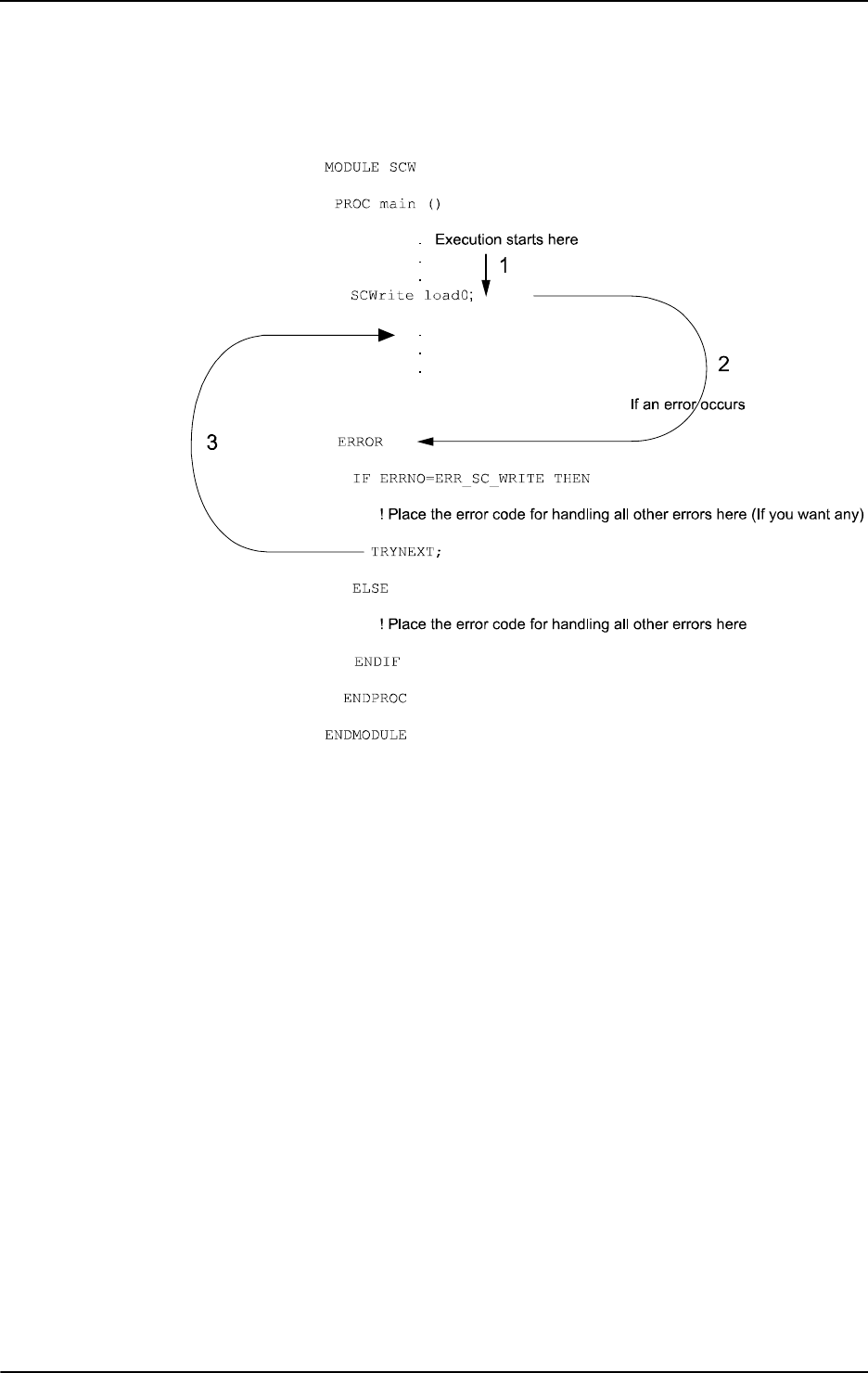
1 Instructions
1.145. SCWrite - Send variable data to a client application
PC interface/backup
4013HAC 16581-1 Revision: J
© Copyright 2004-2010 ABB. All rights reserved.
Using RobotWare 5.0 or later
The RAPID program looks as follows:
xx0500002139
Continued

1 Instructions
1.146. SearchC - Searches circularly using the robot
RobotWare - OS
3HAC 16581-1 Revision: J402
© Copyright 2004-2010 ABB. All rights reserved.
1.146. SearchC - Searches circularly using the robot
Usage
SearchC (Search Circular) is used to search for a position when moving the tool center point
(TCP) circularly.
During the movement the robot supervises a digital input signal. When the value of the signal
changes to the requested one the robot immediately reads the current position.
This instruction can typically be used when the tool held by the robot is a probe for surface
detection. The outline coordinates of a work object can be obtained using the
SearchC
instruction.
This instruction can only be used in the main task
T_ROB1 or, if in a MultiMove system, in
Motion tasks.
When using search instructions it is important to configure the I/O system to have a very short
time from setting the physical signal to the system to get information about the setting (use I/
O unit with interrupt control, not poll control). How to do this can differ between fieldbuses.
If using DeviceNet then the ABB units DSQC 651 (AD Combi I/O) and DSQC 652 (Digital
I/O) will give short times since they are using connection type Change of State. If using other
fieldbuses make sure to configure the network in a proper way to get the right conditions.
Basic examples
Basic examples of the instruction
SearchC are illustrated below.
See also More examples on page 406.
Example 1
SearchC di1, sp, cirpoint, p10, v100, probe;
The TCP of the probe is moved circularly towards the position p10 at a speed of v100.
When the value of the signal
di1 changes to active the position is stored in sp.
Example 1
SearchC \Stop, di2, sp, cirpoint, p10, v100, probe;
The TCP of the probe is moved circularly towards the position p10. When the value of the
signal
di2 changes to active the position is stored in sp and the robot stops immediately.
Continues on next page

1 Instructions
1.146. SearchC - Searches circularly using the robot
RobotWare - OS
4033HAC 16581-1 Revision: J
© Copyright 2004-2010 ABB. All rights reserved.
Arguments
SearchC [\Stop] | [\PStop] | [\SStop] | [\Sup] Signal [\Flanks]
SearchPoint CirPoint ToPoint [\ID] Speed [\V] | [\T] Tool
[\WObj] [\Corr]
[ \Stop ]
Stiff Stop
Data type:
switch
The robot movement is stopped as quickly as possible without keeping the TCP on the path
(hard stop) when the value of the search signal changes to active. However, the robot is
moved a small distance before it stops and is not moved back to the searched position, i.e. to
the position where the signal changed.
-
WAR NIN G!
To stop the searching with stiff stop (switch
\Stop) is only allowed if the TCP-speed is lower
than 100 mm/s. At a stiff stop with higher speeds some axes can move in unpredictable
direction.
[ \PStop ]
Path Stop
Data type:
switch
The robot movement is stopped as quickly as possible while keeping the TCP on the path (soft
stop), when the value of the search signal changes to active. However, the robot is moved a
distance before it stops and is not moved back to the searched position, i.e. to the position
where the signal changed.
[ \SStop ]
Soft Stop
Data type:
switch
The robot movement is stopped as quickly as possible while keeping the TCP close to or on
the path (soft stop) when the value of the search signal changes to active. However, the robot
is moved only a small distance before it stops and is not moved back to the searched position,
i.e. to the position where the signal changed.
SStop is faster then PStop. But when the robot
is running faster than 100 mm/s it stops in the direction of the tangent of the movement which
causes it to marginally slide of the path.
Continued
Continues on next page

1 Instructions
1.146. SearchC - Searches circularly using the robot
RobotWare - OS
3HAC 16581-1 Revision: J404
© Copyright 2004-2010 ABB. All rights reserved.
[ \Sup ]
Supervision
Data type:
switch
The search instruction is sensitive to signal activation during the complete movement (flying
search), i.e. even after the first signal change has been reported. If more than one match
occurs during a search then a recoverable error is generated with the robot in the
ToPoint.
If the argument
\Stop, \PStop, \SStop, or \Sup is omitted (no switch used at all):
• the movement continues (flying search) to the position specified in the ToPoint
argument (same as with argument
\Sup)
• error is reported for none search hit but is not reported for more than one search hit
(first search hit is returned as the
SearchPoint)
Signal
Data type: signaldi
The name of the signal to supervise.
[ \Flanks ]
Data type: switch
The positive and the negative edge of the signal is valid for a search hit.
If the argument
\Flanks is omitted then only the positive edge of the signal is valid for a
search hit, and a signal supervision will be activated at the beginning of a search process. This
means that if the signal has a positive value already at the beginning of the search process or
the communication with the signal is lost, then the robot movement is stopped as quickly as
possible, while keeping the TCP on the path (soft stop). However, the robot is moved a small
distance before it stops and is not moved back to the start position. A user recovery error
(ERR_SIGSUPSEARCH) will be generated and can be dealt with by the error handler.
SearchPoint
Data type: robtarget
The position of the TCP and external axes when the search signal has been triggered. The
position is specified in the outermost coordinate system taking the specified tool, work object,
and active
ProgDisp/ExtOffs coordinate system into consideration.
CirPoint
Data type: robtarget
The circle point of the robot. See the instruction MoveC for a more detailed description of
circular movement. The circle point is defined as a named position or stored directly in the
instruction (marked with an * in the instruction).
ToPoint
Data type: robtarget
The destination point of the robot and external axes. It is defined as a named position or stored
directly in the instruction (marked with an * in the instruction).
SearchC always uses a stop
point as zone data for the destination.
Continued
Continues on next page

1 Instructions
1.146. SearchC - Searches circularly using the robot
RobotWare - OS
4053HAC 16581-1 Revision: J
© Copyright 2004-2010 ABB. All rights reserved.
[ \ID ]
Synchronization id
Data type:
identno
This argument must be used in a MultiMove System if it is a coordinated synchronized
movement, and is not allowed in any other cases.
The specified ID number must be the same in all cooperating program tasks. The ID number
gives a guarantee that the movements are not mixed up at runtime.
Speed
Data type: speeddata
The speed data that applies to movements. Speed data defines the velocity of the tool center
point, the external axes and the tool reorientation.
[ \V ]
Velocity
Data type:
num
This argument is used to specify the velocity of the TCP in mm/s directly in the instruction.
It is then substituted for the corresponding velocity specified in the speed data.
[ \T ]
Time
Data type:
num
This argument is used to specify the total time in seconds during which the robot moves. It is
then substituted for the corresponding speed data.
Tool
Data type: tooldata
The tool in use when the robot moves. The tool center point is the point that is moved to the
specified destination position.
[ \WObj ]
Work Object
Data type:
wobjdata
The work object (coordinate system) to which the robot positions in the instruction are
related.
This argument can be omitted and if so then the position is related to the world coordinate
system. If, on the other hand, a stationary TCP or coordinated external axes are used then this
argument must be specified for a linear movement relative to the work object to be performed.
[ \Corr ]
Correction
Data type:
switch
When this argument is present the correction data written to a corrections entry by the
instruction
CorrWrite will be added to the path and destination position.
Continued
Continues on next page
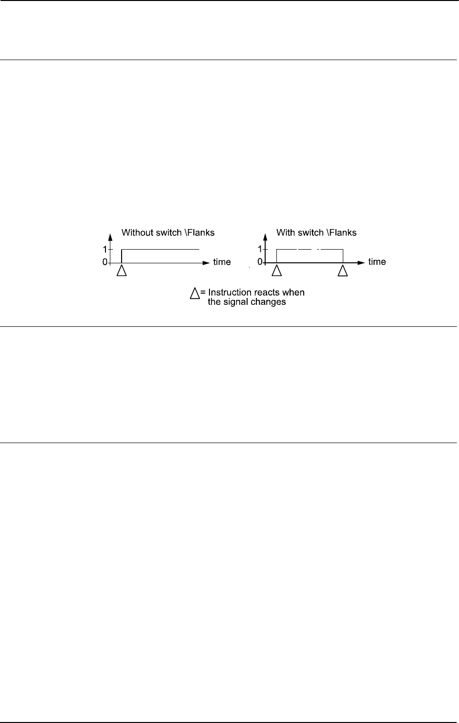
1 Instructions
1.146. SearchC - Searches circularly using the robot
RobotWare - OS
3HAC 16581-1 Revision: J406
© Copyright 2004-2010 ABB. All rights reserved.
Program execution
See the instruction
MoveC for information about circular movement.
The movement is always ended with a stop point, i.e. the robot stops at the destination point.
When a flying search is used, i.e. the
\Sup argument is specified or none switch at all is
specified, the robot movement always continues to the programmed destination point. When
a search is made using the switch
\Stop, \PStop, or \SStop the robot movement stops
when the first search hit is detected.
The
SearchC instruction returns the position of the TCP when the value of the digital signal
changes to the requested one, as illustrated in figure below.
The figure shows how flank-triggered signal detection is used (the position is stored when the
signal is changed the first time only).
xx0500002237
More examples
More examples of how to use the instruction
SearchC are illustrated below.
Example 1
SearchC \Sup, di1\Flanks, sp, cirpoint, p10, v100, probe;
The TCP of the probe is moved circularly towards the position p10. When the value of the
signal
di1 changes to active or passive the position is stored in sp. If the value of the signal
changes twice then program generates an error.
Limitations
General limitations according to instruction
MoveC.
Zone data for the positioning instruction that precedes
SearchC must be used carefully. The
start of the search, i.e. when the I/O signal is ready to react, is not, in this case, the
programmed destination point of the previous positioning instruction but a point along the
real robot path. The figure below illustrates an example of something that may go wrong
when zone data other than
fine is used.
The instruction
SearchC should never be restarted after the circle point has been passed.
Otherwise the robot will not take the programmed path (positioning around the circular path
in another direction compared to that which is programmed).
Continued
Continues on next page
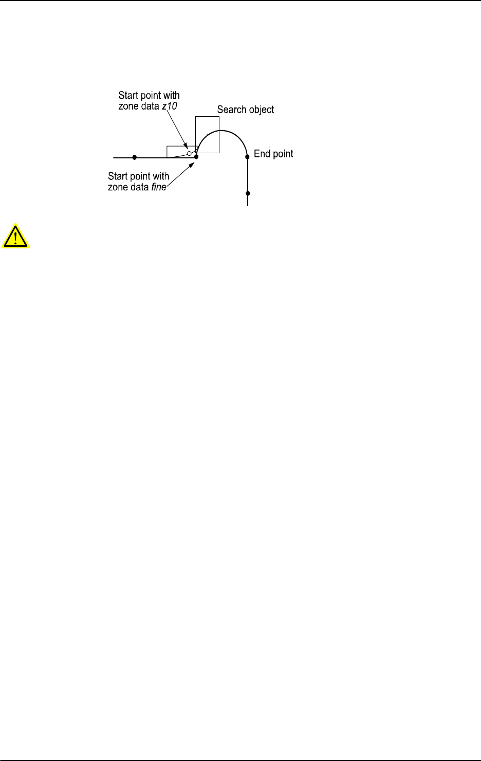
1 Instructions
1.146. SearchC - Searches circularly using the robot
RobotWare - OS
4073HAC 16581-1 Revision: J
© Copyright 2004-2010 ABB. All rights reserved.
The figure shows how a match is made on the wrong side of the object because the wrong
zone data was used.
xx0500002238
WARNING!
Limitations for searching if coordinated synchronized movements:
• If using SearchL, SearchC or SearchExtJ for one program task and some other
move instruction in other program task, it is only possible to use flying search with
switch
\Sup. Besides that, only possible to do error recovery with TRYNEXT.
• It’s possible to use all searching functionality, if using some of the instructions
SearchL
, SearchC or SearchExtJ in all involved program tasks with coordinated
synchronized movements and generate search hit from same digital input signal. This
will generate search hit synchronously in all search instructions. Any error recovery
must also be the same in all involved program tasks.
While searching is active, it isn’t possible to store current path with instruction
StorePath.
Repetition accuracy for search hit position with TCP speed 20 - 1000 mm/s 0.1 - 0.3 mm.
Typical stop distance using a search velocity of 50 mm/s:
• without TCP on path (switch \Stop) 1-3 mm
• with TCP on path (switch \PStop) 15-25 mm
• with TCP near path (switch \SStop) 4-8 mm
Limitations for searching on a conveyor:
• a search will stop the robot when hit or if the search fails, so make the search in the
same direction as the conveyor moves and continue after the search-stop with a move
to a safe position. Use error handling to move to a safe position when search fails.
• the repetition accuracy for the search hit position will be poorer when searching on a
conveyor and depends on the speed of the conveyor and how stabil the speed is.
Continued
Continues on next page

1 Instructions
1.146. SearchC - Searches circularly using the robot
RobotWare - OS
3HAC 16581-1 Revision: J408
© Copyright 2004-2010 ABB. All rights reserved.
Error handling
An error is reported during a search when:
• no signal detection occurred - this generates the error ERR_WHLSEARCH.
• more than one signal detection occurred – this generates the error
ERR_WHLSEARCH only if the
\Sup argument is used.
• the signal already has a positive value at the beginning of the search process or the
communication with the signal is lost. This generates the error
ERR_SIGSUPSEARCH only if the
\Flanks argument is omitted.
Errors can be handled in different ways depending on the selected running mode:
• Continuous forward / Instruction forward / ERR_WHLSEARCH: No position is
returned and the movement always continues to the programmed destination point.
The system variable ERRNO is set to ERR_WHLSEARCH and the error can be
handled in the error handler of the routine.
• Continuous forward / Instruction forward / ERR_SIGSUPSEARCH: No position
is returned and the movement always stops as quickly as possible at the beginning of
the search path. The system variable ERRNO is set to ERR_SIGSUPSEARCH and the
error can be handled in the error handler of the routine.
• Instruction backward: During backward execution the instruction carries out the
movement without any signal supervision.
Syntax
SearchC
[ ’\’ Stop’,’ ] | [ ’\’ PStop ’,’] | [ ’\’ SStop ’,’ ] | [ ’\’
Sup ’,’ ]
[ Signal’:=’ ] < variable (VAR) of signaldi >
[‘\’ Flanks]’,’
[ SearchPoint’:=’ ] < var or pers (INOUT) of robtarget > ’,’
[ CirPoint’:=’ ] < expression (IN) of robtarget > ’,’
[ ToPoint’:=’ ] < expression (IN) of robtarget > ’,’
[ ’\’ ID ’:=’ < expression (IN) of identno >]’,’
[ Speed’:=’ ] < expression (IN) of speeddata >
[ ’\’ V ’:=’ < expression (IN) of num > ]|
[ ’\’ T ’:=’ < expression (IN) of num > ] ’,’
[ Tool ’:=’ ] < persistent (PERS) of tooldata >
[ ’\’ WObj’:=’ < persistent (PERS) of wobjdata > ]
[ ’\’ Corr ]’;’
Continued
Continues on next page

1 Instructions
1.146. SearchC - Searches circularly using the robot
RobotWare - OS
4093HAC 16581-1 Revision: J
© Copyright 2004-2010 ABB. All rights reserved.
Related information
For information about See
Linear searches SearchL - Searches linearly using the robot on page
416
Writes to a corrections entry CorrWrite - Writes to a correction generator on page
77
Moves the robot circularly MoveC - Moves the robot circularly on page 236
Circular movement Technical reference manual - RAPID overview,
section Motion and I/O principles - Positioning during
program execution
Definition of velocity speeddata - Speed data on page 1185
Definition of tools tooldata - Tool data on page 1207
Definition of work objects wobjdata - Work object data on page 1224
Using error handlers Technical reference manual - RAPID overview,
section RAPID summary - Error recovery
Motion in general Technical reference manual - RAPID overview,
section Motion and I/O principles
Continued

1 Instructions
1.147. SearchExtJ - Search with one or several mechanical units without TCP
RobotWare - OS
3HAC 16581-1 Revision: J410
© Copyright 2004-2010 ABB. All rights reserved.
1.147. SearchExtJ - Search with one or several mechanical units without TCP
Usage
SearchExtJ (Search External Joints) is used to search for an external axes position when
moving only linear or rotating external axes. The external axes can belong to one or several
mechanical units without TCP.
During the movement the system supervises a digital input signal. When the value of the
signal changes to the requested one the system immediately reads the current position.
This instruction can only be used if:
• The actual program task is defined as a Motion Task
• The task controls one or several mechanical units without TCP
When using search instructions it is important to configure the I/O system to have a very short
time delay from setting the physical signal until the system gets the information about the
setting (use I/O unit with interrupt control, not poll control). How to do this can differ between
fieldbuses. If using DeviceNet, the ABB units DSQC 651 (AD Combi I/O) and DSQC 652
(Digital I/O) will give a short time delay since they are using the connection type Change of
State. If using other fieldbuses, make sure the network is properly configured in order to get
the correct conditions.
Basic examples
Basic examples of the instruction
SearchExtJ are illustrated below.
See also More examples on page 413.
Example 1
SearchExtJ di1, searchp, jpos10, vrot20;
The mec. unit with rotational axes is moved towards the position jpos10 at a speed of
vrot20. When the value of the signal di1 changes to active, the position is stored in
searchp.
Example 2
SearchExJ \Stop, di2, posx, jpos20, vlin50;
The mec. unit with linear axis is moved towards the position jpos20. When the value of the
signal
di2 changes to active, the position is stored in posx and the ongoing movement is
stopped immediately.
Arguments
SearchExtJ [\Stop] | [\PStop] | [\SStop] | [\Sup] Signal [\Flanks]
SearchJointPos ToJointPos [\ID] [\UseEOffs] Speed [\T]
[ \Stop ]
Stiff Stop
Data type:
switch
The movement is stopped as quickly as possible with hard stop when the value of the search
signal changes to active. However, the external axes are moved a small distance before they
stop and are not moved back to the searched position, i.e. to the position where the signal
changed.
Continues on next page

1 Instructions
1.147. SearchExtJ - Search with one or several mechanical units without TCP
RobotWare - OS
4113HAC 16581-1 Revision: J
© Copyright 2004-2010 ABB. All rights reserved.
[ \PStop ]
Path Stop
Data type:
switch
The movement is stopped with path stop (Program Stop) when the value of the search signal
changes to active. However, the external axes are moved a rather long distance before they
stop and are not moved back to the searched position, i.e. to the position where the signal
changed.
[ \SStop ]
Soft Stop
Data type:
switch
The movement is stopped as quickly as possible with fast soft stop when the value of the
search signal changes to active. However, the external axes are moved only a small distance
before they stop and are not moved back to the searched position, i.e. to the position where
the signal changed.
Stop is faster compare to SStop. SStop is faster compare to PStop.
[ \Sup ]
Supervision
Data type:
switch
The search instruction is sensitive to signal activation during the complete movement (flying
search), i.e. even after the first signal change has been reported. If more than one match
occurs during a search a recoverable error is generated with the mec. units in the
ToJointPos.
If the argument \Stop, \PStop, \SStop or \Sup is omitted (no switch used at all):
• The movement continues (flying search) to the position specified in the ToJointPos
argument (same as with argument
\Sup)
• An error is reported for one search hit but is not reported for more than one search hit
(the first search hit is returned as the
SearchJointPos)
Signal
Data type: signaldi
The name of the signal to supervise.
[ \Flanks ]
Data type: switch
The positive and the negative edge of the signal is valid for a search hit.
If the argument
\Flanks is omitted, only the positive edge of the signal is valid for a search
hit and a signal supervision will be activated at the beginning of a search process. This means
that if the signal already has the positive value at the beginning of a search process or the
communication with the signal is lost, the movement is stopped as quickly as possible with
soft stop. A user recovery error (ERR_SIGSUPSEARCH) will be generated and can be
handled in the error handler.
Continued
Continues on next page

1 Instructions
1.147. SearchExtJ - Search with one or several mechanical units without TCP
RobotWare - OS
3HAC 16581-1 Revision: J412
© Copyright 2004-2010 ABB. All rights reserved.
SearchJointPos
Data type: jointtarget
The position of the external axes when the search signal has been triggered. The position
takes any active
ExtOffs into consideration.
ToJointPos
Data type: jointtarget
The destination point for the external axes. It is defined as a named position or stored directly
in the instruction (marked with an * in the instruction).
SearchExtJ always uses a stop point
as zone data for the destination.
[ \ID ]
Synchronization id
Data type:
identno
This argument must be used in a MultiMove system, if coordinated synchronized movement,
and is not allowed in any other cases.
The specified ID number must be the same in all cooperating program tasks. The ID number
gives a guarantee that the movements are not mixed up at runtime.
[ \UseEOffs ]
Use External Offset
Data type:
switch
The offset for external axes, setup by instruction EOffsSet, is activated for SearchExtJ
instruction when the argument
UseEOffs is used. See instruction EOffsSet for more
information about external offset.
Speed
Data type: speeddata
The speed data that applies to movements. Speed data defines the velocity of the linear or
rotating external axis.
[ \T ]
Time
Data type:
num
This argument is used to specify the total time in seconds during which the mec. units move.
It is then substituted for the corresponding speed data.
Continued
Continues on next page
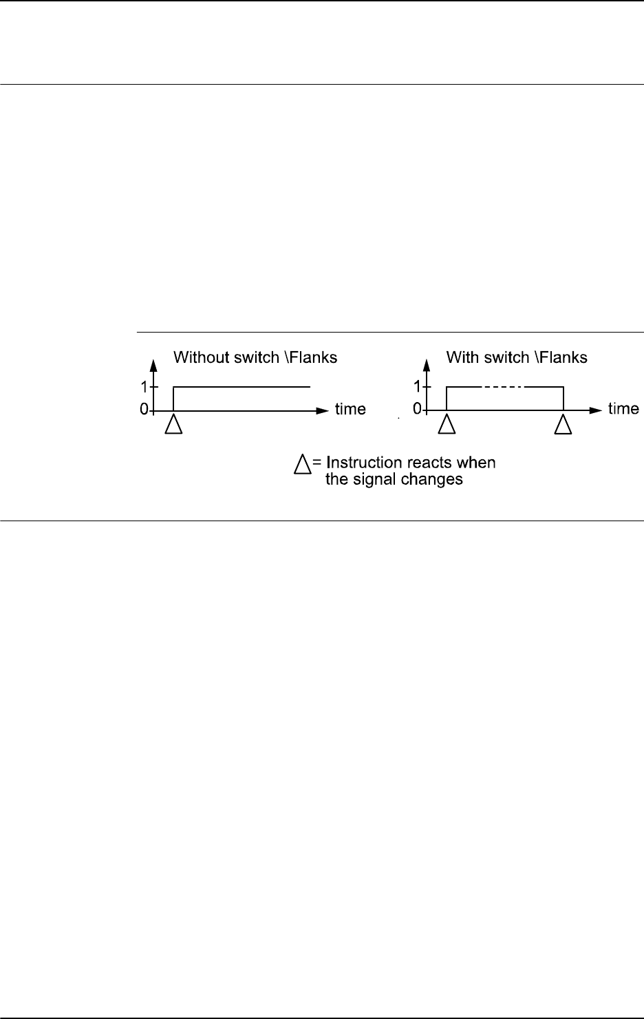
1 Instructions
1.147. SearchExtJ - Search with one or several mechanical units without TCP
RobotWare - OS
4133HAC 16581-1 Revision: J
© Copyright 2004-2010 ABB. All rights reserved.
Program execution
See the instruction
MoveExtJ for information about movement of mechanical units without
TCP.
The movement always ends with a stop point, i.e. the external axes stop at the destination
point. If a flying search is used, that is, the
\Sup argument is specified or no switch is
specified the movement always continues to the programmed destination point. If a search is
made using the switch
\Stop, \PStop or \SStop, the movement stops when the first search
hit is detected.
The
SearchExtJ instruction stores the position of the external axes when the value of the
digital signal changes to the requested one, as illustrated in figure below.
The figure shows how flank-triggered signal detection is used (the position is only stored
when the signal is changed the first time).
xx0500002243
More examples
More examples of how to use the instruction
SearchExtJ are illustrated below.
Example 1
SearchExtJ \Sup, di1\Flanks, searchp,jpos10, vrot20;
The mec. unit is moved towards the position jpos10. When the value of the signal di1
changes to active or passive, the position is stored in searchp. If the value of the signal
changes twice, the program generates an error after the search process is finished.
Example 2
SearchExtJ \Stop, di1, sp, jpos20, vlin50;
MoveExtJ sp, vlin50, fine \Inpos := inpos50;
A check on the signal dil will be made at the beginning of the search process and if the signal
already has a positive value or the communication with the signal is lost, the movement stops.
Otherwise the mec. unit is moved towards the position
jpos20. When the value of the signal
di1 changes to active, the position is stored in sp. The mec. unit is moved back to this point
using an accurately defined stop point.
Continued
Continues on next page

1 Instructions
1.147. SearchExtJ - Search with one or several mechanical units without TCP
RobotWare - OS
3HAC 16581-1 Revision: J414
© Copyright 2004-2010 ABB. All rights reserved.
Error handling
An error is reported during a search when:
• No signal detection occurred - this generates the error ERR_WHLSEARCH.
• More than one signal detection occurred – this generates the error
ERR_WHLSEARCH, but only if the
\Sup argument is used.
• The signal already has a positive value at the beginning of the search process or the
communication with the signal is lost - this generates the error
ERR_SIGSUPSEARCH, but only if the
\Flanks argument is omitted.
Errors can be handled in different ways depending on the selected running mode:
• Continuous forward / Instruction forward / ERR_WHLSEARCH: No position is
returned and the movement always continues to the programmed destination point.
The system variable ERRNO is set to ERR_WHLSEARCH and the error can be
handled in the error handler of the routine.
• Continuous forward / Instruction forward / ERR_SIGSUPSEARCH: No position
is returned and the movement always stops as quickly as possible at the beginning of
the search movement. The system variable ERRNO is set to ERR_SIGSUPSEARCH
and the error can be handled in the error handler of the routine.
• Instruction backward: During backward execution, the instruction just carries out
the movement without any signal supervision.
Example
VAR num fk;
...
MoveExtJ jpos10, vrot100, fine;
SearchExtJ \Stop, di1, sp, jpos20, vrot5;
...
ERROR
IF ERRNO=ERR_WHLSEARCH THEN
StorePath;
MoveExtJ jpos10, vrot50, fine;
RestoPath;
RETRY;
ELSEIF ERRNO=ERR_SIGSUPSEARCH THEN
TPWrite "The signal of the SearchExtJ instruction is already
high!";
TPReadFK fk,"Try again after manual reset of signal
?","YES","stEmpty","stEmpty","stEmpty","NO";
IF fk = 1 THEN
MoveExtJ jpos10, vrot50, fine;
RETRY;
ELSE
Stop;
ENDIF
ENDIF
Continued
Continues on next page

1 Instructions
1.147. SearchExtJ - Search with one or several mechanical units without TCP
RobotWare - OS
4153HAC 16581-1 Revision: J
© Copyright 2004-2010 ABB. All rights reserved.
If the signal is already active at the beginning of the search process or the communication
with the signal is lost, a user dialog will be activated (
TPReadFK ...;). Reset the signal and
push YES on the user dialog and the mec. unit moves back to
jpos10 and tries once more.
Otherwise program execution will stop.
If the signal is passive at the beginning of the search process, the mec. unit searches from
position
jpos10 to jpos20. If no signal detection occurs, the robot moves back to jpos10
and tries once more.
Limitations
Limitations for searching if coordinated synchronized movements:
• If using SearchL, SearchC or SearchExtJ for one program task and some other
move instruction in another program task, it is only possible to use flying search with
switch
\Sup. Besides that, it is only possible to do error recovery with TRYNEXT.
• It is possible to use all searching functions if using some of the instructions SearchL,
SearchC or SearchExtJ in all involved program tasks with coordinated
synchronized movements and generate search hits from the same digital input signal.
This will generate search hits synchronously in all search instructions. Any error
recovery must also be the same in all involved program tasks.
• While searching is active, it isn’t possible to store current path with instruction
StorePath.
Syntax
SearchExtJ
[ ’\’ Stop ’,’ ] | [ ’\’ PStop ’,’] | [ ’\’ SStop ’,’] | [ ’\’
Sup ’,’ ]
[ Signal ’:=’ ] < variable (VAR) of signaldi >
[‘\’ Flanks]’,’
[ SearchJointPos’ :=’ ] < var or pers (INOUT) of jointtarget > ’,’
[ ToJointPos’ :=’ ] < expression (IN) of jointtarget >
[ ’\’ ID ’:=’ < expression (IN) of identno >]’,’
[ ’\’ UseEOffs’ ,’ ]
[ Speed ’:=’ ] < expression (IN) of speeddata >
[ ’\’ T ’:=’ < expression (IN) of num > ] ’;’
Related information
For information about See
Move mec. units without TCP MoveExtJ - Move one or several mechanical units
without TCP on page 250
Definition of jointtarget jointtarget - Joint position data on page 1129
Definition of velocity speeddata - Speed data on page 1185
Using error handlers Technical reference manual - RAPID overview, section
RAPID summary - Error recovery
Motion in general Technical reference manual - RAPID overview, section
Motion and I/O principles
Continued

1 Instructions
1.148. SearchL - Searches linearly using the robot
RobotWare - OS
3HAC 16581-1 Revision: J416
© Copyright 2004-2010 ABB. All rights reserved.
1.148. SearchL - Searches linearly using the robot
Usage
SearchL (Search Linear) is used to search for a position when moving the tool center point
(TCP) linearly.
During the movement the robot supervises a digital input signal. When the value of the signal
changes to the requested one the robot immediately reads the current position.
This instruction can typically be used when the tool held by the robot is a probe for surface
detection. Using the
SearchL instruction the outline coordinates of a work object can be
obtained.
This instruction can only be used in the main task
T_ROB1 or, if in a MultiMove system, in
Motion tasks.
When using search instructions it is important to configure the I/O system to have a very short
time from setting the physical signal to the system to getting the information regarding the
setting (use I/O unit with interrupt control, not poll control). How to do this can differ between
fieldbuses. If using DeviceNet the ABB units DSQC 651 (AD Combi I/O) and DSQC 652
(Digital I/O) will give short times since they are using connection type Change of State. If
using other fieldbuses make sure to configure the network in a proper way to get right
conditions.
Basic examples
Basic examples of the instruction
SearchL are illustrated below.
See also More examples on page 420.
Example 1
SearchL di1, sp, p10, v100, probe;
The TCP of the probe is moved linearly towards the position p10 at a speed of v100. When
the value of the signal
di1 changes to active the position is stored in sp.
Example 2
SearchL \Stop, di2, sp, p10, v100, probe;
The TCP of the probe is moved linearly towards the position p10. When the value of the
signal
di2 changes to active the position is stored in sp and the robot stops immediately.
Continues on next page

1 Instructions
1.148. SearchL - Searches linearly using the robot
RobotWare - OS
4173HAC 16581-1 Revision: J
© Copyright 2004-2010 ABB. All rights reserved.
Arguments
SearchL [\Stop] | [\PStop] | [\SStop] | [\Sup] Signal [\Flanks]
SearchPoint ToPoint [\ID] Speed [\V] | [\T] Tool [\WObj]
[\Corr]
[ \Stop ]
Stiff Stop
Data type:
switch
The robot movement is stopped as quickly as possible without keeping the TCP on the path
(hard stop) when the value of the search signal changes to active. However, the robot is
moved a small distance before it stops and is not moved back to the searched position, i.e. to
the position where the signal changed.
-
WAR NIN G!
To stop the searching with stiff stop (switch
\Stop) is only allowed if the TCP-speed is lower
than 100 mm/s. At a stiff stop with higher speeds some axes can move in unpredictable
directions.
[ \PStop ]
Path Stop
Data type:
switch
The robot movement is stopped as quickly as possible while keeping the TCP on the path (soft
stop) when the value of the search signal changes to active. However, the robot is moved a
distance before it stops and is not moved back to the searched position, i.e. to the position
where the signal changed.
[ \SStop ]
Soft Stop
Data type:
switch
The robot movement is stopped as quickly as possible while keeping the TCP close to or on
the path (soft stop) when the value of the search signal changes to active. However, the robot
is only moved a small distance before it stops and is not moved back to the searched position,
i.e. to the position where the signal changed.
SStop is faster than PStop. But when the robot
is running faster than 100 mm/s it stops in the direction of the tangent of the movement which
causes it to marginally slide off the path.
Continued
Continues on next page

1 Instructions
1.148. SearchL - Searches linearly using the robot
RobotWare - OS
3HAC 16581-1 Revision: J418
© Copyright 2004-2010 ABB. All rights reserved.
[ \Sup ]
Supervision
Data type:
switch
The search instruction is sensitive to signal activation during the complete movement (flying
search), i.e. even after the first signal change has been reported. If more than one match
occurs during a search then a recoverable error is generated with the robot in the
ToPoint.
If the argument
\Stop, \PStop, \SStop, or \Sup is omitted then (no switch used at all):
• the movement continues (flying search) to the position specified in the ToPoint
argument (same as with argument
\Sup)
• error is reported for none search hit but is not reported for more than one search hit
(first search hit is returned as the
SearchPoint)
Signal
Data type: signaldi
The name of the signal to supervise.
[ \Flanks ]
Data type: switch
The positive and the negative edge of the signal is valid for a search hit.
If the argument
\Flanks is omitted, only the positive edge of the signal is valid for a search
hit and a signal supervision will be activated at the beginning of a search process. This means
that if the signal has the positive value already at the beginning of a search process or the
communication with the signal is lost then the robot movement is stopped as quickly as
possible, while keeping the TCP on the path (soft stop). A user recovery error
(ERR_SIGSUPSEARCH) will be generated and can be handled in the error handler.
SearchPoint
Data type: robtarget
The position of the TCP and external axes when the search signal has been triggered. The
position is specified in the outermost coordinate system taking the specified tool, work object,
and active
ProgDisp/ExtOffs coordinate system into consideration.
ToPoint
Data type: robtarget
The destination point of the robot and external axes. It is defined as a named position or stored
directly in the instruction (marked with an * in the instruction).
SearchL always uses a stop
point as zone data for the destination.
[ \ID ]
Synchronization id
Data type:
identno
This argument must be used in a MultiMove system if it is a coordinated synchronized
movement, and is not allowed in any other cases.
The specified ID number must be the same in all cooperating program tasks. The ID number
gives a guarantee that the movements are not mixed up at runtime.
Continued
Continues on next page

1 Instructions
1.148. SearchL - Searches linearly using the robot
RobotWare - OS
4193HAC 16581-1 Revision: J
© Copyright 2004-2010 ABB. All rights reserved.
Speed
Data type: speeddata
The speed data that applies to movements. Speed data defines the velocity of the tool center
point, the external axes, and the tool reorientation.
[ \V ]
Velocity
Data type:
num
This argument is used to specify the velocity of the TCP in mm/s directly in the instruction.
It is then substituted for the corresponding velocity specified in the speed data.
[ \T ]
Time
Data type:
num
This argument is used to specify the total time in seconds during which the robot moves. It is
then substituted for the corresponding speed data.
Tool
Data type: tooldata
The tool in use when the robot moves. The tool center point is the point that is moved to the
specified destination position.
[ \WObj ]
Work Object
Data type:
wobjdata
The work object (coordinate system) to which the robot position in the instruction is related.
This argument can be omitted and if so then the position is related to the world coordinate
system. If, on the other hand, a stationary TCP or coordinated external axes are used then this
argument must be specified for a linear movement relative to the work object to be performed.
[ \Corr ]
Correction
Data type:
switch
Correction data written to a corrections entry by the instruction CorrWrite will be added to
the path and destination position if this argument is present.
Continued
Continues on next page
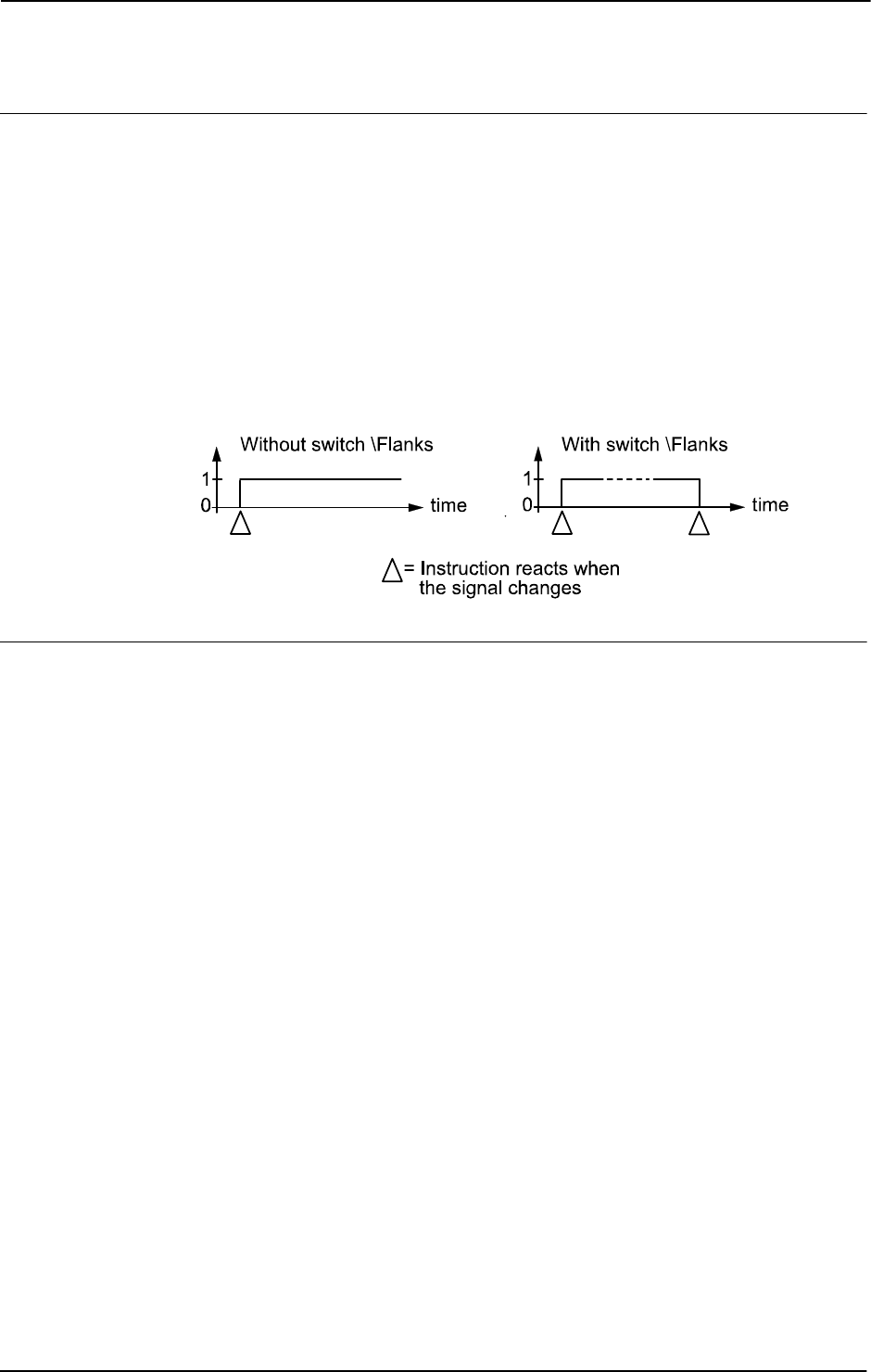
1 Instructions
1.148. SearchL - Searches linearly using the robot
RobotWare - OS
3HAC 16581-1 Revision: J420
© Copyright 2004-2010 ABB. All rights reserved.
Program execution
See the instruction
MoveL for information about linear movement.
The movement always ends with a stop point, i.e. the robot stops at the destination point. If a
flying search is used, i.e. the
\Sup argument is specified or none switch at all is specified
then the robot movement always continues to the programmed destination point. If a search
is made using the switch
\Stop, \PStop, or \SStop the robot movement stops when the
first search hit is detected.
The
SearchL instruction stores the position of the TCP when the value of the digital signal
changes to the requested one, as illustrated in figure below.
The figure shows how flank-triggered signal detection is used (the position is stored when the
signal is changed the first time only).
xx0500002243
More examples
More examples of how to use the instruction
SearchL are illustrated below.
Example 1
SearchL \Sup, di1\Flanks, sp, p10, v100, probe;
The TCP of the probe is moved linearly towards the position p10. When the value of the
signal
di1 changes to active or passive the position is stored in sp. If the value of the signal
changes twice then the program generates an error after the search process is finished.
Example 2
SearchL \Stop, di1, sp, p10, v100, tool1;
MoveL sp, v100, fine \Inpos := inpos50, tool1;
PDispOn *, tool1;
MoveL p100, v100, z10, tool1;
MoveL p110, v100, z10, tool1;
MoveL p120, v100, z10, tool1;
PDispOff;
At the beginning of the search process, a check on the signal di1 will be done and if the signal
already has a positive value or the communication with the signal is lost, the robot stops.
Otherwise the TCP of
tool1 is moved linearly towards the position p10. When the value of
the signal
di1 changes to active, the position is stored in sp. The robot is moved back to
this point using an accurately defined stop point. Using program displacement, the robot then
moves relative to the searched position,
sp.
Continued
Continues on next page
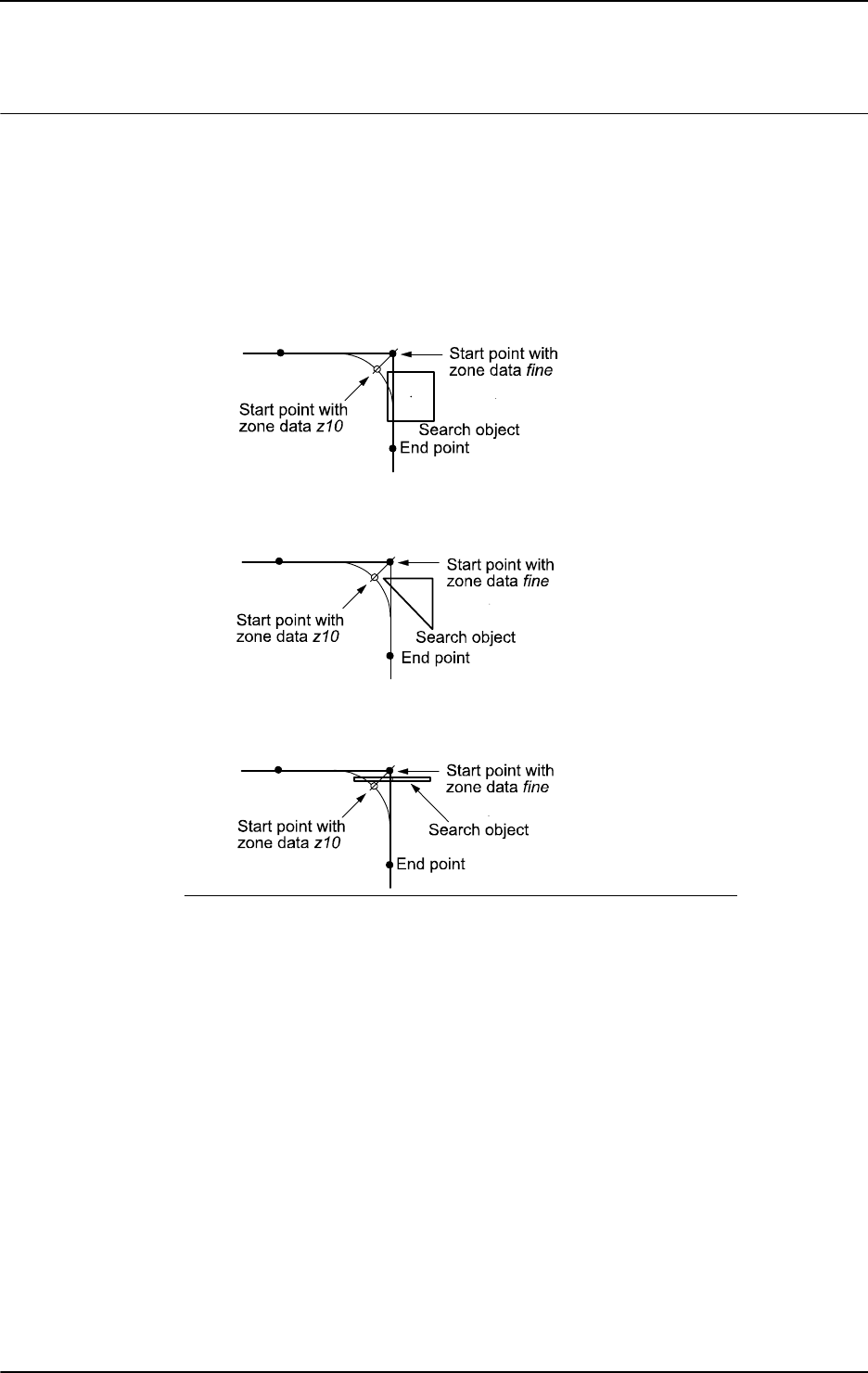
1 Instructions
1.148. SearchL - Searches linearly using the robot
RobotWare - OS
4213HAC 16581-1 Revision: J
© Copyright 2004-2010 ABB. All rights reserved.
Limitations
Zone data for the positioning instruction that precedes
SearchL must be used carefully. The
start of the search, i.e. when the I/O signal is ready to react, is not, in this case, the
programmed destination point of the previous positioning instruction but a point along the
real robot path. The figures below illustrate examples of things that may go wrong when zone
data other than
fine is used.
The following figure shows that a match is made on the wrong side of the object because the
wrong zone data was used.
xx0500002244
The following figure shows that no match was detected because the wrong zone data was
used.
xx0500002245
The following figure shows that no match was detected because the wrong zone data was
used.
xx0500002246
Limitations for searching if coordinated synchronized movements:
• If using SearchL, SearchC or SearchExtJ for one program task and some other
move instruction in other program task, it is only possible to use flying search with
switch
\Sup. Besides that, only possible to do error recovery with TRYNEXT.
• It’s possible to use all searching functionality, if using some of the instructions
SearchL
, SearchC or SearchExtJ in all involved program tasks with coordinated
synchronized movements and generate search hit from same digital input signal. This
will generate search hit synchronously in all search instructions. Any error recovery
must also be the same in all involved program tasks.
While searching is active, it isn’t allowed to store current path with instruction
StorePath.
Repetition accuracy for search hit position with TCP speed 20 - 1000 mm/s 0.1 - 0.3 mm.
Typical stop distance using a search velocity of 50 mm/s:
• without TCP on path (switch \Stop) 1-3 mm
• with TCP on path (switch \PStop) 15-25 mm
• with TCP near path (switch \SStop) 4-8 mm
Continued
Continues on next page

1 Instructions
1.148. SearchL - Searches linearly using the robot
RobotWare - OS
3HAC 16581-1 Revision: J422
© Copyright 2004-2010 ABB. All rights reserved.
Limitations for searching on a conveyor:
• a search will stop the robot when hit or if the search fails, so make the search in the
same direction as the conveyor moves and continue after the search-stop with a move
to a safe position. Use error handling to move to a safe position when search fails.
• the repetition accuracy for the search hit position will be poorer when searching on a
conveyor and depends on the speed of the conveyor and how stabil the speed is.
Error handling
An error is reported during a search when:
• no signal detection occurred - this generates the error ERR_WHLSEARCH.
• more than one signal detection occurred – this generates the error
ERR_WHLSEARCH only if the
\Sup argument is used.
• the signal already has a positive value at the beginning of the search process or the
communication with the signal is lost - this generates the error
ERR_SIGSUPSEARCH only if the
\Flanks argument is omitted.
Errors can be handled in different ways depending on the selected running mode:
• Continuous forward / Instruction forward / ERR_WHLSEARCH: No position is
returned and the movement always continues to the programmed destination point.
The system variable ERRNO is set to ERR_WHLSEARCH and the error can be
handled in the error handler of the routine.
• Continuous forward / Instruction forward / ERR_SIGSUPSEARCH No position is
returned and the movement always stops as quickly as possible at the beginning of the
search path. The system variable ERRNO is set to ERR_SIGSUPSEARCH and the
error can be handled in the error handler of the routine.
• Instruction backward: During backward execution the instruction carries out the
movement without any signal supervision.
Example
VAR num fk;
...
MoveL p10, v100, fine, tool1;
SearchL \Stop, di1, sp, p20, v100, tool1;
...
ERROR
IF ERRNO=ERR_WHLSEARCH THEN
StorePath;
MoveL p10, v100, fine, tool1;
RestoPath;
RETRY;
Continued
Continues on next page

1 Instructions
1.148. SearchL - Searches linearly using the robot
RobotWare - OS
4233HAC 16581-1 Revision: J
© Copyright 2004-2010 ABB. All rights reserved.
ELSEIF ERRNO=ERR_SIGSUPSEARCH THEN
TPWrite "The signal of the SearchL instruction is already
high!";
TPReadFK fk,"Try again after manual reset of signal
?","YES","stEmpty","stEmpty","stEmpty","NO";
IF fk = 1 THEN
MoveL p10, v100, fine, tool1;
RETRY;
ELSE
Stop;
ENDIF
ENDIF
If the signal is already active at the beginning of the search process or the communication
with the signal is lost then a user dialog will be activated (
TPReadFK ...;). Reset the signal
and push YES on the user dialog, and the robot moves back to
p10 and tries once more.
Otherwise program execution will stop.
If the signal is passive at the beginning of the search process then the robot searches from
position
p10 to p20. If no signal detection occurs then the robot moves back to p10 and tries
once more.
Syntax
SearchL
[ ’\’ Stop ’,’ ] | [ ’\’ PStop ’,’] | [ ’\’ SStop ’,’] | [ ’\’
Sup ’,’ ]
[ Signal ’:=’ ] < variable (VAR) of signaldi >
[‘\’ Flanks]’,’
[ SearchPoint’ :=’ ] < var or pers (INOUT) of robtarget > ’,’
[ ToPoint’ :=’ ] < expression (IN) of robtarget >
[ ’\’ ID ’:=’ < expression (IN) of identno >]’,’
[ Speed ’:=’ ] < expression (IN) of speeddata >
[ ’\’ V ’:=’ < expression (IN) of num > ] |
[ ’\’ T ’:=’ < expression (IN) of num > ] ’,’
[ Tool ´:=´ ] < persistent (PERS) of tooldata >
[ ’\’ WObj’ :=’ < persistent (PERS) of wobjdata > ]
[ ’\’ Corr ]’;’
Related information
For information about See
Circular searches SearchC - Searches circularly using the robot on page
402
Writes to a corrections entry CorrWrite - Writes to a correction generator on page 77
Moves the robot linearly MoveL - Moves the robot linearly on page 264
Linear movement Technical reference manual - RAPID overview, section
Motion and I/O principles - Positioning during program
execution
Definition of velocity speeddata - Speed data on page 1185
Definition of tools tooldata - Tool data on page 1207
Continued
Continues on next page

1 Instructions
1.148. SearchL - Searches linearly using the robot
RobotWare - OS
3HAC 16581-1 Revision: J424
© Copyright 2004-2010 ABB. All rights reserved.
Definition of work objects wobjdata - Work object data on page 1224
Using error handlers Technical reference manual - RAPID overview, section
RAPID summary - Error recovery
Motion in general Technical reference manual - RAPID overview, section
Motion and I/O principles
For information about See
Continued

1 Instructions
1.149. SenDevice - connect to a sensor device
Sensor Interface
4253HAC 16581-1 Revision: J
© Copyright 2004-2010 ABB. All rights reserved.
1.149. SenDevice - connect to a sensor device
Usage
SenDevice is used to connect to a sensor device connected to the serial sensor interface.
The sensor interface communicates with sensors over serial channels using the RTP1
transport protocol.
This is an example of a sensor channel configuration.
COM_PHY_CHANNEL:
• Name “COM1:”
• Connector “COM1”
• Baudrate 19200
COM_TRP:
• Name “sen1:”
• Type “RTP1”
• PhyChannel “COM1”
Basic examples
Basic examples of the instruction
SenDevice are illustrated below.
Example 1
! Define variable numbers
CONST num SensorOn := 6;
CONST num XCoord := 8;
CONST num YCoord := 9;
CONST num ZCoord := 10;
VAR pos SensorPos;
! Connect to the sensor device“ sen1:” (defined in sio.cfg).
SenDevice "sen1:";
! Request start of sensor meassurements
WriteVar "sen1:", SensorOn, 1;
! Read a cartesian position from the sensor.
SensorPos.x := ReadVar "sen1:", XCoord;
SensorPos.y := ReadVar "sen1:", YCoord;
SensorPos.z := ReadVar "sen1:", ZCoord;
! Stop sensor
WriteVar "sen1:", SensorOn, 0;
Continues on next page

1 Instructions
1.149. SenDevice - connect to a sensor device
Sensor Interface
3HAC 16581-1 Revision: J426
© Copyright 2004-2010 ABB. All rights reserved.
Arguments
SenDevice device
device
Data type: string
The I/O device name configured in sio.cfg for the sensor used.
Syntax
ReadBlock
[ device‘ :=’ ] < expression(IN) of string>’,’
[ BlockNo’ :=’ ] < expression (IN) of num > ‘,’
[ FileName’ :=’ ] < expression (IN) of string > ‘;’
Related information
For information about See
Write a sensor variable WriteVar - write variable on page 729
Read a sensor variable ReadVar - Read variable from a device on page 958
Write a sensor data block WriteBlock - write block of data to device on page 719
Configuration of sensor com-
munication
Technical reference manual - System parameters, section
Communication
Continued

1 Instructions
1.150. Set - Sets a digital output signal
RobotWare - OS
4273HAC 16581-1 Revision: J
© Copyright 2004-2010 ABB. All rights reserved.
1.150. Set - Sets a digital output signal
Usage
Set is used to set the value of a digital output signal to one.
Basic examples
Basic examples of the instruction
Set are illustrated below.
Example 1
Set do15;
The signal do15 is set to 1.
Example 2
Set weldon;
The signal weldon is set to 1.
Arguments
Set Signal
Signal
Data type: signaldo
The name of the signal to be set to one.
Program execution
There is a short delay before the signal physically gets its new value. If you do not want the
program execution to continue until the signal has got its new value then you can use the
instruction
SetDO with the optional parameter \Sync.
The true value depends on the configuration of the signal. If the signal is inverted in the
system parameters then this instruction causes the physical channel to be set to zero.
Error handling
The following recoverable error can be generated. The error can be handled in an error
handler. The system variable
ERRNO will be set to:
ERR_NORUNUNIT if there is no contact with the unit.
Syntax
Set
[ Signal ’:=’ ] < variable (VAR) of signaldo > ’;’
Continues on next page

1 Instructions
1.150. Set - Sets a digital output signal
RobotWare - OS
3HAC 16581-1 Revision: J428
© Copyright 2004-2010 ABB. All rights reserved.
Related information
For information about See
Setting a digital output signal to zero Reset - Resets a digital output signal on page
359
Change the value of a digital output signal SetDO - Changes the value of a digital output
signal on page 440
Input/Output instructions Technical reference manual - RAPID overview,
section RAPID Summary - Input and output
signals
Input/Output functionality in general Technical reference manual - RAPID overview,
section Motion and I/O Principles - I/O Principles
Configuration of I/O Technical reference manual - System
parameters
Continued

1 Instructions
1.151. SetAllDataVal - Set a value to all data objects in a defined set
RobotWare - OS
4293HAC 16581-1 Revision: J
© Copyright 2004-2010 ABB. All rights reserved.
1.151. SetAllDataVal - Set a value to all data objects in a defined set
Usage
SetAllDataVal(Set All Data Value) makes it possible to set a new value to all data objects
of a certain type that match the given grammar.
Basic examples
Basic examples of the instruction
SetAllDataVal are illustrated below.
VAR mydata mydata0:=0;
...
SetAllDataVal "mydata"\TypeMod:="mytypes"\Hidden,mydata0;
This will set all data objects of data type mydata in the system to the same value that the
variable
mydata0 has (in the example to 0). The user defined data type mydata is defined in
the module
mytypes.
Arguments
SetAllDataVal Type [\TypeMod] [\Object] [\Hidden] Value
Type
Data type: string
The type name of the data objects to be set.
[ \TypeMod ]
Type Module
Data type:
string
The module name where the data type is defined if using user defined data types.
[ \Object ]
Data type: string
The default behavior is to set all data object of the data type above but this option makes it
possible to name one or several objects with a regular expression. (see also instruction
SetDataSearch)
[ \Hidden ]
Data type: switch
This also matches data objects that are in routines (routine data or parameters) hidden by
some routine in the call chain.
Value
Data type: anytype
Variable which holds the new value to be set. The data type must be the same as the data type
for the object to be set.
Continues on next page

1 Instructions
1.151. SetAllDataVal - Set a value to all data objects in a defined set
RobotWare - OS
3HAC 16581-1 Revision: J430
© Copyright 2004-2010 ABB. All rights reserved.
Program running
The instruction will fail if the specification for
Type or TypeMod is wrong.
If the matching data object is an array then all elements of the array will be set to the specified
value.
If the matching data object is read-only data then the value will not be changed.
If the system doesn’t have any matching data objects then the instruction will accept it and
return successfully.
Limitations
For a semivalue data type it is not possible to search for the associated value data type. E.g.
if searching for
dionum then there are no search hits for signal signaldi and if searching
for
num then there are no search hits for signals signalgi or signalai.
It is not possible to set a value to a variable declared as
LOCAL in a built in RAPID module.
Syntax
SetAllDataVal
[ Type ’:=’ ] < expression (IN) of string >
[’\’TypeMod’ :=’<expression (IN) of string>]
[’\’Object’ :=’<expression (IN) of string>]
[’\’Hidden ] ’,’
[ Value ’:=’] <variable (VAR) of anytype>’;’
Related information
For information about See
Define a symbol set in a search
session
SetDataSearch - Define the symbol set in a search
sequence on page 433
Get next matching symbol GetNextSym - Get next matching symbol on page 855
Get the value of a data object GetDataVal - Get the value of a data object on page 110
Set the value of a data object SetDataVal - Set the value of a data object on page 437
The related data type datapos datapos - Enclosing block for a data object on page 1101
Continued
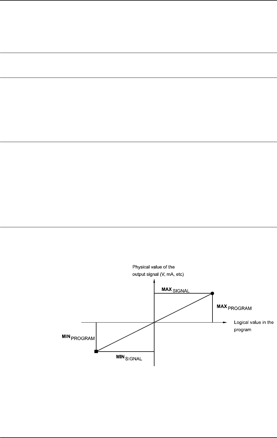
1 Instructions
1.152. SetAO - Changes the value of an analog output signal
RobotWare - OS
4313HAC 16581-1 Revision: J
© Copyright 2004-2010 ABB. All rights reserved.
1.152. SetAO - Changes the value of an analog output signal
Usage
SetAO is used to change the value of an analog output signal.
Basic examples
Basic examples of the instruction
SetAO are illustrated below.
See also More examples on page 432.
Example 1
SetAO ao2, 5.5;
The signal ao2 is set to 5.5.
Arguments
SetAO Signal Value
Signal
Data type: signalao
The name of the analog output signal to be changed.
Value
Data type: num
The desired value of the signal.
Program execution
The programmed value is scaled (in accordance with the system parameters) before it is sent
on the physical channel. A diagram of how analog signal values are scaled is shown in the
figure below.
xx0500002408
Continues on next page

1 Instructions
1.152. SetAO - Changes the value of an analog output signal
RobotWare - OS
3HAC 16581-1 Revision: J432
© Copyright 2004-2010 ABB. All rights reserved.
Error handling
Following recoverable error can be generated. The error can be handled in an error handler.
The system variable
ERRNO will be set to:
ERR_NORUNUNIT
if there is no contact with the unit.
ERR_AO_LIM
if the programmed Value argument for the specified analog output signal Signal is outside
limits.
More examples
More examples of the instruction
SetAO are illustrated below.
Example 1
SetAO weldcurr, curr_outp;
The signal weldcurr is set to the same value as the current value of the variable curr_outp.
Syntax
SetAO
[ Signal ’:=’ ] < variable (VAR) of signalao > ’,’
[ Value ’:=’ ] < expression (IN) of num > ’;’
Related information
For information about See
Input/Output instructions Technical reference manual - RAPID overview,
section RAPID Summary - Input and output signals
Input/Output functionality in general Technical reference manual - RAPID overview,
section Motion and I/O Principles - I/O principles
Configuration of I/O Technical reference manual - System parameters
Continued

1 Instructions
1.153. SetDataSearch - Define the symbol set in a search sequence
RobotWare - OS
4333HAC 16581-1 Revision: J
© Copyright 2004-2010 ABB. All rights reserved.
1.153. SetDataSearch - Define the symbol set in a search sequence
Usage
SetDataSearch is used together with function GetNextSym to retrieve data objects from
the system.
Basic examples
Basic examples of the instruction
SetDataSearch are illustrated below.
Example 1
VAR datapos block;
VAR string name;
...
SetDataSearch "robtarget"\InTask;
WHILE GetNextSym(name,block \Recursive) DO
...
This session will find all robtarget’s object in the task.
Arguments
SetDataSearch Type [\TypeMod] [\Object] [\PersSym]
[\VarSym][\ConstSym] [\InTask] | [\InMod]
[\InRout][\GlobalSym] | [\LocalSym]
Type
Data type: string
The data type name of the data objects to be retrieved.
[ \TypeMod ]
Type Module
Data type:
string
The module name where the data type is defined, if using user defined data types.
[ \Object ]
Data type: string
The default behavior is to set all data objects of the data type above, but this option makes it
possible to name one or several data objects with a regular expression.
A regular expression is a powerful mechanism to specify a grammar to match the data object
names. The string could consist of either ordinary characters and meta characters. A meta
character is a special operator used to represent one or more ordinary characters in the string
with the purpose to extend the search. It is possible to see if a string matches a specified
pattern as a whole or search within a string for a substring matching a specified pattern.
Within a regular expression all alphanumeric characters match themselves. That is to say that
the pattern "abc" will only match a data object named "abc". To match all data object names
containing the character sequence "abc" it is necessary to add some meta characters. The
regular expression for this is ".*abc.*".
Continues on next page

1 Instructions
1.153. SetDataSearch - Define the symbol set in a search sequence
RobotWare - OS
3HAC 16581-1 Revision: J434
© Copyright 2004-2010 ABB. All rights reserved.
The available meta character set is shown below.
The default behavior is to accept any symbols but if one or several of following
PersSym,
VarSym, or ConstSym is specified then only symbols that match the specification are
accepted:
[ \PersSym ]
Persistent Symbols
Data type:
switch
Accept persistent variable (PERS) symbols.
[ \VarSym ]
Variable Symbols
Data type:
switch
Accept variable (VAR) symbols.
[ \ConstSym ]
Constant Symbols
Data type:
switch
Accept constant (CONST) symbols.
If not one of the flags \
InTask or \InMod are specified then the search is started at system
level. The system level is the root to all other symbol definitions in the symbol tree. At the
system level all build- in symbols are located plus the handle to the task level. At the task
level all loaded global symbols are located plus the handle to the modules level.
If the \
Recursive flag is set in GetNextSym then the search session will enter all loaded
modules and routines below the system level.
Expression Meaning
. Any single character.
[s] Any single character in the non-empty set s, where s is a
sequence of characters. Ranges may be specified as c-c.
[^s] Any single character not in the set s.
r* Zero or more occurrences of the regular expression r.
r+ One or more occurrences of the regular expression r
r? Zero or one occurrence of the regular expression r.
(r) The regular expression r. Used for separate that regular
expression from another.
r | r’ The regular expressions r or r’.
.* Any character sequence (zero, one, or several characters).
Continued
Continues on next page

1 Instructions
1.153. SetDataSearch - Define the symbol set in a search sequence
RobotWare - OS
4353HAC 16581-1 Revision: J
© Copyright 2004-2010 ABB. All rights reserved.
[ \InTask ]
In Task
Data type:
switch
Start the search at the task level. At the task level all loaded global symbols are located plus
the handle to the modules level.
If the \
Recursive flag is set in GetNextSym then the search session will enter all loaded
modules and routines below the task level.
[ \InMod ]
In Module
Data type:
string
Start the search at the specified module level. At the module level all loaded global and local
symbols declared in the specified module are located plus the handle to the routines level.
If the \
Recursive flag is set in GetNextSym then the search session will enter all loaded
routines below the specified module level (declared in the specified module).
[ \InRout ]
In Routine
Data type:
string
Search only at the specified routine level.
The module name for the routine must be specified in the argument \
InMod.
The default behavior is to match both local and global module symbols, but if one of
following \
GlobalSym or \LocalSym is specified then only symbols that match the
specification are accepted:
[ \GlobalSym ]
Global Symbols
Data type:
switch
Skip local module symbols.
[ \LocalSym ]
Local Symbols
Data type:
switch
Skip global module symbols.
Program running
The instruction will fail if the specification for one of
Type, TypeMod, InMod, or InRout is
wrong.
If the system doesn’t have any matching objects the instruction will accept it and return
successfully but the first
GetNextSym will return FALSE.
Continued
Continues on next page

1 Instructions
1.153. SetDataSearch - Define the symbol set in a search sequence
RobotWare - OS
3HAC 16581-1 Revision: J436
© Copyright 2004-2010 ABB. All rights reserved.
Limitations
Array data objects cannot be defined in the symbol search set and cannot be found in a search
sequence.
For a semivalue data type it is not possible to search for the associated value data type. E.g.
if searching for
dionum then there are no search hits for signal signaldi and if searching
for
num then there are no search hits for signals signalgi or signalai.
Installed built-in symbols declared as
LOCAL will never be found, irrespective of use of
argument
\GlobalSym, \LocalSym or none of these.
Installed built-in symbols declared as global or as
TASK will always be found, irrespective of
use of argument
\GlobalSym, \LocalSym or none of these.
It is not possible to use
SetDataSearch for searching for data of some ALIAS data type
defined with
RAPID code. No limitation for predefined ALIAS data type.
Syntax
SetDataSearch
[ Type ’:=’ ] < expression (IN) of string >
[’\’TypeMod ’:=’<expression (IN) of string>]
[’\’Object ’:=’<expression (IN) of string>]
[’\’PersSym ]
[’\’VarSym ]
[’\’ConstSym ]
[’\’InTask ]
| [’\’InMod’ :=’<expression (IN) of string>]
[’\’InRout ’:=’<expression (IN) of string>]
[’\’GlobalSym ]
| [’\’LocalSym]’ ;’
Related information
For information about See
Get next matching symbol GetNextSym - Get next matching symbol on page 855
Get the value of a data object GetDataVal - Get the value of a data object on page
110
Set the value of many data objects SetAllDataVal - Set a value to all data objects in a
defined set on page 429
The related data type datapos datapos - Enclosing block for a data object on page
1101
Continued

1 Instructions
1.154. SetDataVal - Set the value of a data object
RobotWare - OS
4373HAC 16581-1 Revision: J
© Copyright 2004-2010 ABB. All rights reserved.
1.154. SetDataVal - Set the value of a data object
Usage
SetDataVal (Set Data Value) makes it possible to set a value for a data object that is
specified with a string variable.
Basic examples
Basic examples of the instruction
SetDataVal are illustrated below.
Example 1
VAR num value:=3;
...
SetDataVal "reg"+ValToStr(ReadNum(mycom)),value;
This will set the value 3 to a register with a number that is received from the serial channel
mycom.
Example 2
VAR datapos block;
VAR bool truevar:=TRUE;
...
SetDataSearch "bool" \Object:="my.*" \InMod:="mymod"\LocalSym;
WHILE GetNextSym(name,block) DO
SetDataVal name\Block:=block,truevar;
ENDWHILE
This session will set all local bool that begin with my in the module mymod to TRUE.
Example 3
VAR string StringArrVar_copy{2};
...
StringArrVar_copy{1} := "test1";
StringArrVar_copy{2} := "test2";
SetDataVal "StringArrVar", StringArrVar_copy;
This session will set the array StringArrVar to contain the two strings test1 and test2.
Arguments
SetDataVal Object [\Block]|[\TaskRef]|[\TaskName] Value
Object
Data type: string
The name of the data object.
[ \Block ]
Data type: datapos
The enclosed block to the data object. This can only be fetched with the GetNextSym
function.
If this argument is omitted then the value of the visible data object in the current program
execution scope will be set.
Continues on next page

1 Instructions
1.154. SetDataVal - Set the value of a data object
RobotWare - OS
3HAC 16581-1 Revision: J438
© Copyright 2004-2010 ABB. All rights reserved.
[\TaskRef]
Task Reference
Data type:
taskid
The program task identity in which to search for the data object specified. When using this
argument, you may search for
PERS or TASK PERS declarations in other tasks, any other
declarations will result in an error.
For all program tasks in the system the predefined variables of the data type
taskid will be
available. The variable identity will be "taskname"+"Id", e.g. for the
T_ROB1 task the variable
identity will be
T_ROB1Id.
[\TaskName]
Data type: string
The program task name in which to search for the data object specified. When using this
argument, you may search for
PERS or TASK PERS declarations in other tasks, any other
declarations will result in an error.
Value
Data type: anytype
Variable which holds the new value to be set. The data type must be the same as the data type
for the data object to be set. The set value must be fetched from a variable but can be stored
in a variable or persistent.
Error handling
The system variable
ERRNO is set to ERR_SYM_ACCESS if:
• the data object is non-existent
• the data object is read-only data
• the data object is routine data or routine parameter and not located in the current active
routine
• searching in other tasks for other declarations then PERS or TASK PERS
When using the arguments TaskRef or TaskName you may search for PERS or TASK PERS
declarations in other tasks, any other declarations will result in an error and the system
variable
ERRNO is set to ERR_SYM_ACCESS. Searching for a PERS declared as LOCAL in other
tasks will also result in an error and the system variable
ERRNO is set to ERR_SYM_ACCESS.
The system variable
ERRNO is set to ERR_INVDIM if the data object and the variable used in
argument
Value have different dimensions.
The error can be handled in the error handler of the routine.
Limitations
For a semivalue data type it is not possible to search for the associated value data type. E.g.
if searching for
dionum then no search hit for signal signaldi will be obtained and if
searching for
num then no search hit for signals signalgi or signalai will be obtained.
It is not possible to set a value to a variable declared as
LOCAL in a built-in RAPID module.
Continued
Continues on next page

1 Instructions
1.154. SetDataVal - Set the value of a data object
RobotWare - OS
4393HAC 16581-1 Revision: J
© Copyright 2004-2010 ABB. All rights reserved.
Syntax
SetDataVal
[ Object ’:=’ ] < expression (IN) of string >
[’\’Block’ :=’<variable (VAR) of datapos>]
|[ ’\’TaskRef’ :=’ <variable (VAR) of taskid>]
|[ ’\’TaskName’ :=’ <expression (IN) of string>] ’,’]
[ Value ’:=’ ] <variable (VAR) of anytype>]’;’
Related information
For information about See
Define a symbol set in a search session SetDataSearch - Define the symbol set in a
search sequence on page 433
Get next matching symbol GetNextSym - Get next matching symbol on page
855
Get the value of a data object GetDataVal - Get the value of a data object on
page 110
Set the value of many data objects SetAllDataVal - Set a value to all data objects in a
defined set on page 429
The related data type datapos datapos - Enclosing block for a data object on
page 1101
Continued

1 Instructions
1.155. SetDO - Changes the value of a digital output signal
RobotWare - OS
3HAC 16581-1 Revision: J440
© Copyright 2004-2010 ABB. All rights reserved.
1.155. SetDO - Changes the value of a digital output signal
Usage
SetDO is used to change the value of a digital output signal, with or without a time delay or
synchronization.
Basic examples
Basic examples of the instruction
SetDO are illustrated below.
Example 1
SetDO do15, 1;
The signal do15 is set to 1.
Example 2
SetDO weld, off;
The signal weld is set to off.
Example 3
SetDO \SDelay := 0.2, weld, high;
The signal weld is set to high with a delay of 0.2 s. However, program execution continues
with the next instruction.
Example 4
SetDO \Sync ,do1, 0;
The signal do1 is set to 0. Program execution waits until the signal is physically set to the
specified value.
Arguments
SetDO [ \SDelay ]|[ \Sync ] Signal Value
[ \SDelay ]
Signal Delay
Data type:
num
Delays the change for the amount of time given in seconds (max. 2000 s). Program execution
continues directly with the next instruction. After the given time delay the signal is changed
without the rest of the program execution being affected.
[ \Sync ]
Synchronization
Data type:
switch
If this argument is used then the program execution will wait until the signal is physically set
to the specified value.
Signal
Data type: signaldo
The name of the signal to be changed.
Continues on next page

1 Instructions
1.155. SetDO - Changes the value of a digital output signal
RobotWare - OS
4413HAC 16581-1 Revision: J
© Copyright 2004-2010 ABB. All rights reserved.
Value
Data type: dionum
The desired value of the signal 0 or 1.
Program execution
The true value depends on the configuration of the signal. If the signal is inverted in the
system parameters then the value of the physical channel is the opposite.
If neither of the arguments
\SDelay or \Sync are used then the signal will be set as fast as
possible, and the next instruction will be executed at once without waiting for the signal to be
physically set.
Limitations
If a
SetDO with a \SDelay argument is followed by a new SetDO on the same signal, with
or without
\SDelay argument, then the first SetDO will be cancelled if the second SetDO is
executed before the delay time of the first
SetDO have expired.
Error handling
The following recoverable error can be generated. The error can be handled in an error
handler. The system variable
ERRNO will be set to:
ERR_NORUNUNIT
if there is no contact with the unit.
ERR_ARGVALERR
if the value for the SDelay argument exceeds the maximum value allowed (2000 s).
Syntax
SetDO
[ ’\’ SDelay ’:=’ < expression (IN) of num > ’,’ ]
|[ ’\’ Sync ’,’ ]
[ Signal ’:=’ ] < variable (VAR) of signaldo > ’,’
[ Value ’:=’ ] < expression (IN) of dionum > ’;’
Related information
Specified Value Set digital output to
0 0
Any value except 0 1
For information about See
Input/Output instructions Technical reference manual - RAPID overview,
section RAPID Summary - input and output signals
Input/Output functionality in general Technical reference manual - RAPID overview,
section Motion and I/O Principles - I/O Principles
Configuration of I/O Technical reference manual - System parameters
Continued

1 Instructions
1.156. SetGO - Changes the value of a group of digital output signals
RobotWare - OS
3HAC 16581-1 Revision: J442
© Copyright 2004-2010 ABB. All rights reserved.
1.156. SetGO - Changes the value of a group of digital output signals
Usage
SetGO is used to change the value of a group of digital output signals with or without a time
delay.
Basic examples
Basic examples of the instruction
SetGO are illustrated below.
Example 1
SetGO go2, 12;
The signal go2 is set to 12. If go2 comprises 4 signals, e.g. outputs 6-9, then outputs 6 and
7 are set to zero while outputs 8 and 9 are set to one.
Example 2
SetGO \SDelay := 0.4, go2, 10;
The signal go2 is set to 10. If go2 comprises 4 signals, e.g. outputs 6-9, then outputs 6 and
8 are set to zero while outputs 7 and 9 are set to one with a delay of
0.4 s. However program
execution continues with the next instruction.
Example 3
SetGO go32, 4294967295;
The signal go32 is set to 4294967295. go32 comprises 32 signals, which are all set to one.
Arguments
SetGO [ \SDelay ] Signal Value | Dvalue
[ \SDelay ]
Signal Delay
Data type:
num
Delays the change for the period of time stated in seconds (max. 2000 s). Program execution
continues directly with the next instruction. After the specified time delay the value of the
signals is changed without the rest of the program execution being affected.
If the argument is omitted then the signal values are changed directly.
Signal
Data type: signalgo
The name of the signal group to be changed.
Value
Data type: num
The desired value of the signal group (a positive integer) is shown in the table below.
The permitted value is dependent on the number of signals in the group. A
num datatype can
hold the value for a group of 23 signals or less.
Continues on next page

1 Instructions
1.156. SetGO - Changes the value of a group of digital output signals
RobotWare - OS
4433HAC 16581-1 Revision: J
© Copyright 2004-2010 ABB. All rights reserved.
Dvalue
Data type: dnum
The desired value of the signal group (a positive integer) is shown in the table below.
The permitted value is dependent on the number of signals in the group. A dnum datatype can
hold the value for a group of 32 signals or less.
*) The
Value argument of type num can only hold up to 23 signals compared to the Dvalue
argument of type
dnum that can hold up to 32 signals.
No. of signals Permitted Value Permitted Dvalue
1 0-1 0-1
2 0-3 0-3
3 0-7 0-7
4 0-15 0-15
5 0-31 0-31
6 0-63 0-63
7 0-127 0-127
8 0-255 0-255
9 0-511 0-511
10 0-1023 0-1023
11 0-2047 0-2047
12 0-4095 0-4095
13 0-8191 0-8191
14 0-16383 0-16383
15 0-32767 0-32767
16 0-65535 0-65535
17 0-131071 0-131071
18 0-262143 0-262143
19 0-524287 0-524287
20 0-1048575 0-1048575
21 0-2097151 0-2097151
22 0-4194303 0-4194303
23 0-8388607 0-8388607
24 * 0-16777215
25 * 0-33554431
26 * 0-67108863
27 * 0-134217727
28 * 0-268435455
29 * 0-536870911
30 * 0-1073741823
31 * 0-2147483647
32 * 0-4294967295
Continued
Continues on next page

1 Instructions
1.156. SetGO - Changes the value of a group of digital output signals
RobotWare - OS
3HAC 16581-1 Revision: J444
© Copyright 2004-2010 ABB. All rights reserved.
Program execution
The programmed value is converted to an unsigned binary number. This binary number is sent
on the signal group with the result that individual signals in the group are set to 0 or 1. Due
to internal delays the value of the signal may be undefined for a short period of time.
Limitations
Maximum number of signals that can be used for a group is 23 if argument
Value is used and
32 if argument
Dvalue is used. This limitation is valid for all instructions and functions using
group signals.
Error handling
The following recoverable error can be generated. The error can be handled in an error
handler. The system variable
ERRNO will be set to:
ERR_NORUNUNIT
if there is no contact with the unit.
ERR_ARGVALERR
if the value for the SDelay argument exceeds the maximum value allowed (2000 s).
ERR_GO_LIM
if the programmed Value or Dvalue argument for the specified digital group output signal
Signal is outside limits.
Syntax
SetGO
[ ’\’ SDelay ’:=’ < expression (IN) of num > ’,’ ]
[ Signal ’:=’ ] < variable (VAR) of signalgo > ’,’
[ Value ’:=’ ] < expression (IN) of num >
| [ Dvalue’ :=’ ] < expression (IN) of dnum > ’;’
Related information
For information about See
Other input/output instructions Technical reference manual - RAPID overview,
section RAPID Summary - Input and output
signals
Input/Output functionality in general Technical reference manual - RAPID overview,
section Motion and I/O Principles - I/O principles
Configuration of I/O (system parameters) Technical reference manual - System parameters
Continued

1 Instructions
1.157. SetSysData - Set system data
RobotWare - OS
4453HAC 16581-1 Revision: J
© Copyright 2004-2010 ABB. All rights reserved.
1.157. SetSysData - Set system data
Usage
SetSysData activates the specified system data name for the specified data type.
With this instruction it is possible to change the current active Tool, Work Object, or PayLoad
for the robot in actual or connected motion task.
Basic examples
Basic examples of the instruction
SetSysData are illustrated below.
Example 1
SetSysData tool5;
The tool tool5 is activated.
SetSysData tool0 \ObjectName := "tool6";
The tool tool6 is activated.
SetSysData anytool \ObjectName := "tool2";
The tool tool2 is activated.
Arguments
SetSysData SourceObject [\ObjectName]
SourceObject
Data type: anytype
Persistent variable that should be active as current system data.
The data type of this argument also specifies the type of system data to be activated for the
robot in actual or connected motion task.
Entire array or record component can not be used.
[ \ObjectName ]
Data type: string
If this optional argument is specified then it specifies the name of the data object to be active
(overrides name specified in argument
SourceObject). The data type of the data object to
be active is always fetched from the argument
SourceObject.
Program execution
The current active system data object for the Tool, Work Object, or PayLoad is set according
to the arguments.
Note that this instruction only activates a new data object (or the same as before) and never
changes the value of any data object.
Data type Type of system data
tooldata Tool
wobjdata Work Object
loaddata Payload
Continues on next page

1 Instructions
1.157. SetSysData - Set system data
RobotWare - OS
3HAC 16581-1 Revision: J446
© Copyright 2004-2010 ABB. All rights reserved.
Syntax
SetSysData
[ SourceObject’:=’] < persistent(PERS) of anytype>
[’\’ObjectName’:=’ < expression (IN) of string> ] ’;’
Related information
For information about See
Definition of tools tooldata - Tool data on page 1207
Definition of work objects wobjdata - Work object data on page 1224
Definition of payload loaddata - Load data on page 1132
Get system data GetSysData - Get system data on page 113
Continued

1 Instructions
1.158. SingArea - Defines interpolation around singular points
RobotWare - OS
4473HAC 16581-1 Revision: J
© Copyright 2004-2010 ABB. All rights reserved.
1.158. SingArea - Defines interpolation around singular points
Usage
SingArea is used to define how the robot is to move in the proximity of singular points.
SingArea is also used to define linear and circular interpolation for robots with less than six
axes.
This instruction can only be used in the main task
T_ROB1 or, if in a MultiMove system, in
Motion tasks.
Basic examples
Basic examples of the instruction
SingArea are illustrated below.
Example 1
SingArea \Wrist;
The orientation of the tool may be changed slightly in order to pass a singular point (axes 4
and 6 in line).
Robots with less than six axes may not be able to reach an interpolated tool orientation. By
using
SingArea \Wrist the robot can achieve the movement but the orientation of the tool
will be slightly changed.
Example 2
SingArea \Off;
The tool orientation is not allowed to differ from the programmed orientation. If a singular
point is passed then one or more axes may perform a sweeping movement resulting in a
reduction in velocity.
Robots with less than six axes may not be able to reach a programmed tool orientation. As a
result the robot will stop.
Arguments
SingArea [\Wrist]|[\Off]
[ \Wrist ]
Data type: switch
The tool orientation is allowed to differ somewhat in order to avoid wrist singularity. Used
when axes 4 and 6 are parallel (axis 5 at 0 degrees). Also used for linear and circular
interpolation of robots with less than six axes where the tool orientation is allowed to differ.
[ \Off ]
Data type: switch
The tool orientation is not allowed to differ. Used when no singular points are passed or when
the orientation is not permitted to be changed.
If none of the arguments are specified the system will be set to
\Off.
Continues on next page

1 Instructions
1.158. SingArea - Defines interpolation around singular points
RobotWare - OS
3HAC 16581-1 Revision: J448
© Copyright 2004-2010 ABB. All rights reserved.
Program execution
If the arguments
\Wrist is specified then the orientation is joint-interpolated to avoid
singular points. In this way the TCP follows the correct path, but the orientation of the tool
deviates somewhat. This will also happen when a singular point is not passed.
The specified interpolation applies to all subsequent movements until a new
SingArea
instruction is executed.
The movement is only affected on execution of linear or circular interpolation.
By default, program execution automatically uses the
Off argument for robots with six axes.
Robots with less than six axes may use either the
Off argument or the /Wrist argument by
default. This is automatically set in event routine
SYS_RESET.
• at a cold start-up.
• when a new program is loaded.
• when starting program execution from the beginning.
Syntax
SingArea
[ ’\’ Wrist ] | [’\’ Off ] ’;’
Related information
For information about See
Singularity Technical reference manual - RAPID overview,
section Motion and I/O principles - Singularities
Interpolation Technical reference manual - RAPID overview,
section Motion and I/O principles - Positioning
during program execution
Continued

1 Instructions
1.159. SkipWarn - Skip the latest warning
RobotWare-OS
4493HAC 16581-1 Revision: J
© Copyright 2004-2010 ABB. All rights reserved.
1.159. SkipWarn - Skip the latest warning
Usage
SkipWarn (Skip Warning) is used to skip the latest generated warning message to be stored
in the Event Log during execution in running mode continuously or cycle (no warnings
skipped in FWD or BWD step).
With
SkipWarn it is possible to repeatedly do error recovery in RAPID without filling the
Event Log with only warning messages.
Basic examples
Basic examples of the instruction
SkipWarn are illustrated below.
Example 1
%"notexistingproc"%;
nextinstruction;
ERROR
IF ERRNO = ERR_REFUNKPRC THEN
SkipWarn;
TRYNEXT;
ENDIF
ENDPROC
The program will execute the nextinstruction and no warning message will be stored in
the Event Log.
Syntax
SkipWarn ’;’
Related information
For information about See
Error recovery Technical reference manual - RAPID overview, section
RAPID Summary - Error Recovery
Technical reference manual - RAPID overview, section
Basic Characteristics - Error Recovery
Error number errnum - Error number on page 1108

1 Instructions
1.160. SocketAccept - Accept an incoming connection
Socket Messaging
3HAC 16581-1 Revision: J450
© Copyright 2004-2010 ABB. All rights reserved.
1.160. SocketAccept - Accept an incoming connection
Usage
SocketAccept is used to accept incoming connection requests. SocketAccept can only be
used for server applications.
Basic examples
Basic examples of the instruction
SocketAccept are illustrated below.
See also More examples on page 451.
Example 1
VAR socketdev server_socket;
VAR socketdev client_socket;
...
SocketCreate server_socket;
SocketBind server_socket,"192.168.0.1", 1025;
SocketListen server_socket;
SocketAccept server_socket, client_socket;
A server socket is created and bound to port 1025 on the controller network address
192.168.0.1. After execution of SocketListen the server socket starts to listen for
incoming connections on this port and address.
SocketAccept waits for any incoming
connections, accepts the connection request, and returns a client socket for the established
connection.
Arguments
SocketAccept Socket ClientSocket [\ClientAddress] [ \Time ]
Socket
Data type: socketdev
The server sockets that are waiting for incoming connections. The socket must already be
created, bounded, and ready for listening.
ClientSocket
Data type: socketdev
The returned new client socket that will be updated with the accepted incoming connection
request.
[\ClientAddress]
Data type: string
The variable that will be updated with the IP-address of the accepted incoming connection
request.
Continues on next page

1 Instructions
1.160. SocketAccept - Accept an incoming connection
Socket Messaging
4513HAC 16581-1 Revision: J
© Copyright 2004-2010 ABB. All rights reserved.
[\Time]
Data type: num
The maximum amount of time [s] that program execution waits for incoming connections. If
this time runs out before any incoming connection then the error handler will be called, if
there is one, with the error code
ERR_SOCK_TIMEOUT. If there is no error handler then the
execution will be stopped.
If parameter
\Time is not used then the waiting time is 60 s. To wait forever, use the
predefined constant
WAIT_MAX.
Program execution
The server socket will wait for any incoming connection requests. When accepting the
incoming connection request the instruction is ready and the returned client socket is by
default connected and can be used in
SocketSend and SocketReceive instructions.
More examples
More examples of the instruction
SocketAccept are illustrated below.
Example 1
VAR socketdev server_socket;
VAR socketdev client_socket;
VAR string receive_string;
VAR string client_ip;
...
SocketCreate server_socket;
SocketBind server_socket, "192.168.0.1", 1025;
SocketListen server_socket;
WHILE TRUE DO
SocketAccept server_socket, client_socket
\ClientAddress:=client_ip;
SocketReceive client_socket \Str := receive_string;
SocketSend client_socket \Str := "Hello client with ip-address "
+client_ip;
! Wait for client acknowledge
...
SocketClose client_socket;
ENDWHILE
ERROR
RETRY;
UNDO
SocketClose server_socket;
SocketClose client_socket;
A server socket is created and bound to port 1025 on the controller network address
192.168.0.1. After execution of SocketListen the server socket starts to listen for
incoming connections on this port and address.
SocketAccept will accept the incoming
connection from some client and store the client address in the string
client_ip. Then the
server receives a string message from the client and stores the message in
receive_string.
Then the server responds with the message
" Hello client with ip-address
xxx.xxx.x.x"
and closes the client connection.
Continued
Continues on next page

1 Instructions
1.160. SocketAccept - Accept an incoming connection
Socket Messaging
3HAC 16581-1 Revision: J452
© Copyright 2004-2010 ABB. All rights reserved.
After that the server is ready for a connection from the same or some other client in the WHILE
loop. If PP is moved to main in the program then all open sockets are closed (
SocketClose
can always be done even if the socket is not created).
Error handling
The following recoverable errors can be generated. The errors can be handled in an
ERROR
handler. The system variable
ERRNO will be set to:
Syntax
SocketAccept
[ Socket ´:=´ ] < variable (VAR) of socketdev > ’,’
[ ClientSocket ´:=´ ] < variable (VAR) of socketdev >
[ ’\’ ClientAddress ´:=´ < variable (VAR) of string> ]
[ ’\’ Time ´:=´ < expression (IN) of num > ] ’;’
Related information
ERR_SOCK_CLOSED The socket is closed (has been closed or is not created).
Use SocketCreate to create a new socket.
ERR_SOCK_TIMEOUT The connection was not established within the time out time
For information about See
Socket communication in general Application manual - Robot communication and I/
O control, section Socket Messaging
Create a new socket SocketCreate - Create a new socket on page 460
Connect to remote computer (only client) SocketConnect - Connect to a remote computer
on page 457
Send data to remote computer SocketSend - Send data to remote computer on
page 469
Receive data from remote computer SocketReceive - Receive data from remote
computer on page 464
Close the socket SocketClose - Close a socket on page 455
Bind a socket (only server) SocketBind - Bind a socket to my IP-address and
port on page 453
Listening connections (only server) SocketListen - Listen for incoming connections
on page 462
Get current socket state SocketGetStatus - Get current socket state on
page 973
Example client socket application SocketSend - Send data to remote computer on
page 469
Example of server socket application SocketReceive - Receive data from remote
computer on page 464
Continued

1 Instructions
1.161. SocketBind - Bind a socket to my IP-address and port
Socket Messaging
4533HAC 16581-1 Revision: J
© Copyright 2004-2010 ABB. All rights reserved.
1.161. SocketBind - Bind a socket to my IP-address and port
Usage
SocketBind is used to bind a socket to the specified server IP-address and port number.
SocketBind can only be used for server applications.
Basic examples
Basic examples of the instruction
SocketBind are illustrated below.
Example 1
VAR socketdev server_socket;
SocketCreate server_socket;
SocketBind server_socket, "192.168.0.1", 1025;
A server socket is created and bound to port 1025 on the controller network address
192.168.0.1. The server socket can now be used in an SocketListen instruction to listen
for incoming connections on this port and address.
Arguments
SocketBind Socket LocalAddress LocalPort
Socket
Data type: socketdev
The server socket to bind. The socket must be created but not already bound.
LocalAddress
Data type: string
The server network address to bind the socket to. The only valid addresses are any public
LAN addresses or the controller service port address 192.168.125.1.
LocalPort
Data type: num
The server port number to bind the socket to. Generally ports 1025-4999 are free to use. Ports
below 1025 can already be taken.
Program execution
The server socked is bound to the specified server port and IP-address.
An error is generated if the specified port is already in use.
Use the
SocketBind and SocketListen instructions in the startup of the program to
associate a local address with a socket and then listen for incoming connections on the
specified port. This is recommended to do only once for each socket and port that is used.
Continues on next page

1 Instructions
1.161. SocketBind - Bind a socket to my IP-address and port
Socket Messaging
3HAC 16581-1 Revision: J454
© Copyright 2004-2010 ABB. All rights reserved.
Error handling
The following recoverable errors can be generated. The errors can be handled in an
ERROR
handler. The system variable
ERRNO will be set to:
Syntax
SocketBind
[ Socket ´:=´ ] < variable (VAR) of socketdev > ’,’
[ LocalAddress ´:=´ ] < expression (IN) of string > ’,’
[ LocalPort ´:=´ ] < expression (IN) of num > ’;’
Related information
ERR_SOCK_CLOSED The socket is closed (has been closed or is not created)
Use SocketCreate to create a new socket.
ERR_SOCK_ADDR_INUSE The address and port is already in use and can not be used
again. Use a different port number..
For information about See
Socket communication in general Application manual - Robot communication and I/
O control, section Socket Messaging
Create a new socket SocketCreate - Create a new socket on page 460
Connect to remote computer (only client) SocketConnect - Connect to a remote computer
on page 457
Send data to remote computer SocketSend - Send data to remote computer on
page 469
Receive data from remote computer SocketReceive - Receive data from remote
computer on page 464
Close the socket SocketClose - Close a socket on page 455
Listening connections (only server) SocketListen - Listen for incoming connections on
page 462
Accept connections (only server) SocketAccept - Accept an incoming connection
on page 450
Get current socket state SocketGetStatus - Get current socket state on
page 973
Example client socket application SocketSend - Send data to remote computer on
page 469
Example server socket application SocketReceive - Receive data from remote
computer on page 464
Continued

1 Instructions
1.162. SocketClose - Close a socket
Socket Messaging
4553HAC 16581-1 Revision: J
© Copyright 2004-2010 ABB. All rights reserved.
1.162. SocketClose - Close a socket
Usage
SocketClose is used when a socket connection is no longer going to be used.
After a socket has been closed it cannot be used in any socket call except
SocketCreate.
Basic examples
Basic examples of the instruction
SocketClose are illustrated below.
Example 1
SocketClose socket1;
The socket is closed and can not be used anymore.
Arguments
SocketClose Socket
Socket
Data type: socketdev
The socket to be closed.
Program execution
The socket will be closed and its allocated resources will be released.
Any socket can be closed at any time. The socket can not be used after closing. However it
can be reused for a new connection after a call to
SocketCreate.
Limitations
Closing the socket connection immediately after sending the data with
SocketSend can lead
to loss of sent data. This is because
TCP/IP socket has built-in functionality to resend the data
if there is some communication problem.
To avoid such problems with loss of data, do the following before
SocketClose:
• handshake the shutdown or
• WaitTime 2
Avoid fast loops with
SocketCreate ... SocketClose, because the socket is not really
closed until a certain time (TCP/IP functionality).
Syntax
SocketClose
[ Socket ’:=’ ] < variable (VAR) of socketdev > ’;’
Continues on next page

1 Instructions
1.162. SocketClose - Close a socket
Socket Messaging
3HAC 16581-1 Revision: J456
© Copyright 2004-2010 ABB. All rights reserved.
Related information
For information about See
Socket communication in general Application manual - Robot communication and I/
O control, section Socket Messaging
Create a new socket SocketCreate - Create a new socket on page 460
Connect to a remote computer
(only client)
SocketConnect - Connect to a remote computer
on page 457
Send data to remote computer SocketSend - Send data to remote computer on
page 469
Receive data from remote computer SocketReceive - Receive data from remote
computer on page 464
Bind a socket (only server) SocketBind - Bind a socket to my IP-address and
port on page 453
Listening connections (only server) SocketListen - Listen for incoming connections on
page 462
Accept connections (only server) SocketAccept - Accept an incoming connection
on page 450t
Get current socket state SocketGetStatus - Get current socket state on
page 973
Example client socket application SocketSend - Send data to remote computer on
page 469
Example server socket application SocketReceive - Receive data from remote
computer on page 464
Continued

1 Instructions
1.163. SocketConnect - Connect to a remote computer
Socket Messaging
4573HAC 16581-1 Revision: J
© Copyright 2004-2010 ABB. All rights reserved.
1.163. SocketConnect - Connect to a remote computer
Usage
SocketConnect is used to connect the socket to a remote computer in a client application.
Basic examples
Basic examples of the instruction
SocketConnect are illustrated below.
See also More examples on page 458.
Example 1
SocketConnect socket1, "192.168.0.1", 1025;
Trying to connect to a remote computer at ip-address 192.168.0.1 and port 1025.
Arguments
SocketConnect Socket Address Port [\Time]
Socket
Data type: socketdev
The client socket to connect. The socket must be created but not already connected.
Address
Data type: string
The address of the remote computer. The remote computer must be specified as an IP address.
It is not possible to use the name of the remote computer.
Port
Data type: num
The port on the remote computer. Generally ports 1025-4999 are free to use. Ports below 1025
can already be taken.
[ \Time ]
Data type: num
The maximum amount of time [s] that program execution waits for the connection to be
accepted or denied. If this time runs out before the condition is met then the error handler will
be called, if there is one, with the error code
ERR_SOCK_TIMEOUT. If there is no error handler
then the execution will be stopped.
If parameter
\Time is not used the waiting time is 60 s. To wait forever, use the predefined
constant
WAIT_MAX.
Program execution
The socket tries to connect to the remote computer on the specified address and port. The
program execution will wait until the connection is established, failed, or a timeout occurs.
Continues on next page

1 Instructions
1.163. SocketConnect - Connect to a remote computer
Socket Messaging
3HAC 16581-1 Revision: J458
© Copyright 2004-2010 ABB. All rights reserved.
More examples
More examples of the instruction
SocketConnect are illustrated below.
Example 1
VAR num retry_no := 0;
VAR socketdev my_socket;
...
SocketCreate my_socket;
SocketConnect my_socket, "192.168.0.1", 1025;
...
ERROR
IF ERRNO = ERR_SOCK_TIMEOUT THEN
IF retry_no < 5 THEN
WaitTime 1;
retry_no := retry_no + 1;
RETRY;
ELSE
RAISE;
ENDIF
ENDIF
A socket is created and tries to connect to a remote computer. If the connection is not
established within the default time-out time, i.e. 60 seconds, then the error handler retries to
connect. Four retries are attemped then the error is reported to the user.
Error handling
The following recoverable errors can be generated. The errors can be handled in an
ERROR
handler. The system variable
ERRNO will be set to:
Syntax
SocketConnect
[ Socket ´:=´ ] < variable (VAR) of socketdev > ’,’
[ Address ´:=´ ] < expression (IN) of string > ’,’
[ Port ´:=´ ] < expression (IN) of num >
[ ’\’ Time ´:=´ < expression (IN) of num > ] ’;’
ERR_SOCK_CLOSED The socket is closed (has been closed or is not created).
Use SocketCreate to create a new socket.
ERR_SOCK_TIMEOUT The connection was not established within the time-out time.
Continued
Continues on next page

1 Instructions
1.163. SocketConnect - Connect to a remote computer
Socket Messaging
4593HAC 16581-1 Revision: J
© Copyright 2004-2010 ABB. All rights reserved.
Related information
For information about Described in:
Socket communication in general Application manual - Robot communication and
I/O control
Create a new socket SocketCreate - Create a new socket on page 460
Send data to remote computer SocketSend - Send data to remote computer on
page 469
Receive data from remote computer SocketReceive - Receive data from remote
computer on page 464
Bind a socket (only server) SocketBind - Bind a socket to my IP-address and
port on page 453
Listening connections (only server) SocketListen - Listen for incoming connections
on page 462
Accept connections (only server) SocketAccept - Accept an incoming connection
on page 450
Get current socket state SocketGetStatus - Get current socket state on
page 973
Example client socket application SocketSend - Send data to remote computer on
page 469
Example server socket application SocketReceive - Receive data from remote
computer on page 464
Continued

1 Instructions
1.164. SocketCreate - Create a new socket
Socket Messaging
3HAC 16581-1 Revision: J460
© Copyright 2004-2010 ABB. All rights reserved.
1.164. SocketCreate - Create a new socket
Usage
SocketCreate is used to create a new socket for connection based communication.
The socket messaging is of stream type protocol TCP/IP with delivery guarantee. Both server
and client application can be developed. Datagram protocol UDP/IP with broadcast is not
supported.
Basic examples
Basic examples of the instruction
SocketCreate are illustrated below.
Example 1
VAR socketdev socket1;
...
SocketCreate socket1;
A new socket device is created and assigned into the variable socket1.
Arguments
SocketCreate Socket
Socket
Data type: socketdev
The variable for storage of the system’s internal socket data.
Program execution
The instruction creates a new socket device.
The socket must not already be in use. The socket is in use between
SocketCreate and
SocketClose.
Limitations
Any number of sockets can be declared but it is only possible to use 8 sockets at the same
time.
Avoid fast loops with
SocketCreate ... SocketClose, because the socket is not really
closed until a certain time (TCP/IP functionality).
Syntax
SocketCreate
[ Socket ’:=’ ] < variable (VAR) of socketdev > ’;’
Continues on next page

1 Instructions
1.164. SocketCreate - Create a new socket
Socket Messaging
4613HAC 16581-1 Revision: J
© Copyright 2004-2010 ABB. All rights reserved.
Related information
For information about See
Socket communication in general Application manual - Robot communication and
I/O control, section Socket Messaging
Connect to remote computer (only client) SocketConnect - Connect to a remote computer
on page 457
Send data to remote computer SocketSend - Send data to remote computer on
page 469
Receive data from remote computer SocketReceive - Receive data from remote
computer on page 464
Close the socket SocketClose - Close a socket on page 455
Bind a socket (only server) SocketBind - Bind a socket to my IP-address
and port on page 453
Listening connections (only server) SocketListen - Listen for incoming connections
on page 462
Accept connections (only server) SocketAccept - Accept an incoming connection
on page 450
Get current socket state SocketGetStatus - Get current socket state on
page 973
Example client socket application SocketSend - Send data to remote computer on
page 469
Example server socket application SocketReceive - Receive data from remote
computer on page 464
Continued

1 Instructions
1.165. SocketListen - Listen for incoming connections
Socket Messaging
3HAC 16581-1 Revision: J462
© Copyright 2004-2010 ABB. All rights reserved.
1.165. SocketListen - Listen for incoming connections
Usage
SocketListen is used to start listening for incoming connections, i.e. start acting as a server.
SocketListen can only used for server applications.
Basic examples
Basic examples of the instruction
SocketListen are illustrated below.
Example 1
VAR socketdev server_socket;
VAR socketdev client_socket;
...
SocketCreate server_socket;
SocketBind server_socket, "192.168.0.1", 1025;
SocketListen server_socket;
WHILE listening DO;
! Waiting for a connection request
SocketAccept server_socket, client_socket;
A server socket is created and bound to port 1025 on the controller network address
192.168.0.1. After execution of SocketListen the server socket starts to listen for
incoming connections on this port and address.
Arguments
SocketListen Socket
Socket
Data type: socketdev
The server socket that should start listening for incoming connections. The socket must
already be created and bound.
Program execution
The server socket start listening for incoming connections. When the instruction is ready the
socket is ready to accept an incoming connection.
Use the
SocketBind and SocketListen instructions in the startup of the program to
associate a local address with a socket and then listen for incoming connections on the
specified port. This is recommended to do only once for each socket and port that is used.
Error handling
The following recoverable errors can be generated. The errors can be handled in an
ERROR
handler. The system variable
ERRNO will be set to:
Syntax
SocketListen
[ Socket ’:=’ ] < variable (VAR) of socketdev > ’;’
ERR_SOCK_CLOSED The socket is closed (has been closed or is not created).
Use SocketCreate to create a new socket.
Continues on next page

1 Instructions
1.165. SocketListen - Listen for incoming connections
Socket Messaging
4633HAC 16581-1 Revision: J
© Copyright 2004-2010 ABB. All rights reserved.
Related information
For information about See
Socket communication in general Application manual - Robot communication and
I/O control, section Socket Messaging
Create a new socket SocketCreate - Create a new socket on page
460
Connect to remote computer (only client) SocketConnect - Connect to a remote computer
on page 457
Send data to remote computer SocketSend - Send data to remote computer on
page 469
Receive data from remote computer SocketReceive - Receive data from remote
computer on page 464
Close the socket SocketClose - Close a socket on page 455
Bind a socket (only server) SocketBind - Bind a socket to my IP-address and
port on page 453
Accept connections (only server) SocketAccept - Accept an incoming connection
on page 450
Get current socket state SocketGetStatus - Get current socket state on
page 973
Example client socket application SocketSend - Send data to remote computer on
page 469
Example server socket application SocketReceive - Receive data from remote
computer on page 464
Continued

1 Instructions
1.166. SocketReceive - Receive data from remote computer
Socket Messaging
3HAC 16581-1 Revision: J464
© Copyright 2004-2010 ABB. All rights reserved.
1.166. SocketReceive - Receive data from remote computer
Usage
SocketReceive is used for receiving data from a remote computer. SocketReceive can
be used both for client and server applications.
Basic examples
Basic examples of the instruction
SocketReceive are illustrated below.
See also More examples on page 466.
Example 1
VAR string str_data;
...
SocketReceive socket1 \Str := str_data;
Receive data from a remote computer and store it in the string variable str_data.
Arguments
SocketReceive Socket [ \Str ] | [ \RawData ] | [ \Data ]
[\ReadNoOfBytes] [\NoRecBytes] [\Time]
Socket
Data type: socketdev
In a client application where the socket receives the data, the socket must already be created
and connected.
In a server application where the socket receives the data, the socket must already be
accepted.
[ \Str ]
Data type: string
The variable in which the received string data should be stored. Max. number of characters
80 can be handled.
[ \RawData ]
Data type: rawbytes
The variable in which the received rawbytes data should be stored. Max. number of
rawbytes 1024 can be handled.
[ \Data ]
Data type: array of byte
The variable in which the received byte data should be stored. Max. number of byte 1024
can be handled.
Only one of the optional parameters
\Str, \RawData, and \Data can be used at the same
time.
Continues on next page

1 Instructions
1.166. SocketReceive - Receive data from remote computer
Socket Messaging
4653HAC 16581-1 Revision: J
© Copyright 2004-2010 ABB. All rights reserved.
[ \ReadNoOfBytes ]
Read number of Bytes
Data type:
num
The number of bytes to read. The minimum value of bytes to read is 1, and the maximum
amount is the value of the size of the data type used, i.e. 80 bytes if using a variable of the
data type
string.
If communicating with a client that always sends a fixed number of bytes, this optional
parameter can be used to specify that the same amount of bytes should be read for each
SocketReceive instruction.
If the sender sends RawData, the receiver needs to specify that 4 bytes should be received for
each
rawbytes sent.
[ \NoRecBytes ]
Number Received Bytes
Data type:
num
Variable for storage of the number of bytes needed from the specified socketdev.
The same result can also be achieved with
• function StrLen on varable in argument \Str
• function RawBytesLen on variable in argument \RawData
[ \Time ]
Data type: num
The maximum amount of time [s] that program execution waits for the data to be received. If
this time runs out before the data is transferred then the error handler will be called, if there
is one, with the error code
ERR_SOCK_TIMEOUT. If there is no error handler then the
execution will be stopped.
If parameter
\Time is not used then the waiting time is 60 s. To wait forever, use the
predefined constant
WAIT_MAX.
Program execution
The execution of
SocketReceive will wait until the data is available or fail with a timeout
error.
The amount of bytes read is specified by the the data type used in the instruction. If using a
string data type to receive data in, 80 bytes is received if there is 80 bytes that can be read.
If using optional argument
ReadNoOfBytes the user can specify how many bytes that should
be received for each
SocketReceive.
The data that is transferred on the cable is always bytes, max. 1024 bytes in one message. No
header is added by default to the message. The usage of any header is reserved for the actual
application.
Parameter Input data Cable data Output data
\Str 1 char 1 byte (8 bits) 1 char
\RawData 1 rawbytes 1 byte (8 bits) 1 rawbytes
\Data 1 byte 1 byte (8 bits) 1 byte
Continued
Continues on next page

1 Instructions
1.166. SocketReceive - Receive data from remote computer
Socket Messaging
3HAC 16581-1 Revision: J466
© Copyright 2004-2010 ABB. All rights reserved.
It is possible to mix the used data type (string, rawbytes, or array of byte) between
SocketSend and SocketReceive.
More examples
More examples of the instruction
SocketReceive are illustrated below.
Example 1
VAR socketdev server_socket;
VAR socketdev client_socket;
VAR string client_ip;
PROC server_messaging()
VAR string receive_string;
...
! Create, bind, listen and accept of sockets in error handlers
SocketReceive client_socket \Str := receive_string;
SocketSend client_socket \Str := "Hello client with
ip-address "+client_ip;
! Wait for acknowlegde from client
...
SocketClose server_socket;
SocketClose client_socket;
ERROR
IF ERRNO=ERR_SOCK_TIMEOUT THEN
RETRY;
ELSEIF ERRNO=SOCK_CLOSED THEN
server_recover;
RETRY;
ELSE
! No error recovery handling
ENDIF
ENDPROC
PROC server_recover()
SocketClose server_socket;
SocketClose client_socket;
SocketCreate server_socket;
SocketBind server_socket, "192.168.0.1", 1025;
SocketListen server_socket;
SocketAccept server_socket,
client_socket\ClientAddress:=client_ip;
ERROR
IF ERRNO=ERR_SOCK_TIMEOUT THEN
RETRY;
ELSEIF ERRNO=ERR_SOCK_CLOSED THEN
RETURN;
ELSE
! No error recovery handling
Continued
Continues on next page

1 Instructions
1.166. SocketReceive - Receive data from remote computer
Socket Messaging
4673HAC 16581-1 Revision: J
© Copyright 2004-2010 ABB. All rights reserved.
ENDIF
ENDPROC
This is an example of a server program with creation, binding, listening, and accepting of
sockets in error handlers. In this way the program can handle power fail restart.
In the procedure
server_recover, a server socket is created and bound to port 1025 on the
controller network address
192.168.0.1. After execution of SocketListen the server
socket starts to listen for incoming connections on this port and address.
SocketAccept will
accept the incoming connection from some client and store the client address in the string
client_ip.
In the communication procedure
server_messaging the server receives a string message
from the client and stores the message in
receive_string. Then the server responds with
the message
"Hello client with ip-address xxx.xxx.x.x".
Error handling
The following recoverable errors can be generated. The errors can be handled in an
ERROR
handler. The system variable
ERRNO will be set to:
Limitations
There is no built-in synchronization mechanism in Socket Messaging to avoid received
messages that are compounded of several sent messages. It is up to the programmer to handle
the synchronization with “Ack” messages (one sequence of
SocketSend -
SocketReceive
in the client or server program must be completed before next sequence of
SocketSend - SocketReceive).
All sockets are closed after power fail restart. This problem can be handled by error recovery.
See example above.
Avoid fast loops with
SocketCreate ... SocketClose because the socket is not really
closed until a certain time (TCP/IP functionality).
The maximum size of the data that can be received in one call is limited to 1024 bytes.
Syntax
SocketReceive
[ Socket ’:=’ ] < variable (VAR) of socketdev >
[ ’\’ Str’ :=’ < variable (VAR) of string > ]
| [ ’\’ RawData ´:=´ < variable (VAR) of rawbytes > ]
| [ ’\’ Data ´:=´ < array {*} (VAR) of byte > ]
[ ’\’ ReadNoOfBytes’ :=’ < expression (IN) of num > ]
[ ’\’ NoRecBytes’ :=’ < variable (VAR) of num > ]
[ ’\’ Time ´:=´ < expression (IN) of num > ] ’;’
ERR_SOCK_CLOSED The socket is closed. Broken connection.
ERR_SOCK_TIMEOUT No data was received within the time out time.
Continued
Continues on next page

1 Instructions
1.166. SocketReceive - Receive data from remote computer
Socket Messaging
3HAC 16581-1 Revision: J468
© Copyright 2004-2010 ABB. All rights reserved.
Related information
For information about See
Socket communication in general Application manual - Robot communication and I/
O control, section Socket Messaging
Create a new socket SocketCreate - Create a new socket on page 460
Connect to remote computer (only client) SocketConnect - Connect to a remote computer
on page 457
Send data to remote computer SocketSend - Send data to remote computer on
page 469
Close the socket SocketClose - Close a socket on page 455
Bind a socket (only server) SocketBind - Bind a socket to my IP-address and
port on page 453
Listening connections (only server) SocketListen - Listen for incoming connections
on page 462
Accept connections (only server) SocketAccept - Accept an incoming connection
on page 450
Get current socket state SocketGetStatus - Get current socket state on
page 973
Example client socket application SocketSend - Send data to remote computer on
page 469
Continued

1 Instructions
1.167. SocketSend - Send data to remote computer
Socket Messaging
4693HAC 16581-1 Revision: J
© Copyright 2004-2010 ABB. All rights reserved.
1.167. SocketSend - Send data to remote computer
Usage
SocketSend is used to send data to a remote computer. SocketSend can be used both for
client and server applications.
Basic examples
Basic examples of the instruction
SocketSend are illustrated below.
See also More examples on page 470.
Example 1
SocketSend socket1 \Str := "Hello world";
Sends the message "Hello world" to the remote computer.
Arguments
SocketSend Socket [ \Str ] | [ \RawData ] | [ \Data] [ \NoOfBytes ]
Socket
Data type: socketdev
In client application the socket to send from must already be created and connected.
In server application the socket to send to must already be accepted.
[ \Str ]
Data type: string
The string to send to the remote computer.
[ \RawData ]
Data type: rawbytes
The rawbytes data to send to the remote computer.
[ \Data ]
Data type: array of byte
The data in the byte array to send to the remote computer.
Only one of the option parameters
\Str, \RawData, or \Data can be used at the same time.
[ \NoOfBytes ]
Data type: num
If this argument is specified only this number of bytes will be sent to the remote computer.
The call to
SocketSend will fail if \NoOfBytes is larger than the actual number of bytes in
the data structure to send.
If this argument is not specified then the whole data structure (valid part of
rawbytes) will
be sent to the remote computer.
Continues on next page

1 Instructions
1.167. SocketSend - Send data to remote computer
Socket Messaging
3HAC 16581-1 Revision: J470
© Copyright 2004-2010 ABB. All rights reserved.
Program execution
The specified data is sent to the remote computer. If the connection is broken an error is
generated.
The data that is transferred on the cable is always bytes, max. 1024 bytes in one message. No
header is added by default to the message. The usage of any header is reserved for the actual
application.
It’s possible to mix the used data type (
string, rawbytes, or array of byte) between
SocketSend and SocketReceive.
More examples
More examples of the instruction
SocketSend are illustrated below.
Example 1
VAR socketdev client_socket;
VAR string receive_string;
PROC client_messaging()
...
! Create and connect the socket in error handlers
SocketSend client_socket \Str := "Hello server";
SocketReceive client_socket \Str := receive_string;
...
SocketClose client_socket;
ERROR
IF ERRNO=ERR_SOCK_TIMEOUT THEN
RETRY;
ELSEIF ERRNO=ERR_SOCK_CLOSED THEN
client_recover;
RETRY;
ELSE
! No error recovery handling
ENDIF
ENDPROC
PROC client_recover()
SocketClose client_socket;
SocketCreate client_socket;
SocketConnect client_socket, "192.168.0.2", 1025;
ERROR
IF ERRNO=ERR_SOCK_TIMEOUT THEN
RETRY;
Parameter Input data Cable data Output data
\Str 1 char 1 byte (8 bits) 1 char
\RawData 1 rawbytes 1 byte (8 bits) 1 rawbytes
\Data 1 byte 1 byte (8 bits) 1 byte
Continued
Continues on next page

1 Instructions
1.167. SocketSend - Send data to remote computer
Socket Messaging
4713HAC 16581-1 Revision: J
© Copyright 2004-2010 ABB. All rights reserved.
ELSEIF ERRNO=ERR_SOCK_CLOSED THEN
RETURN;
ELSE
! No error recovery handling
ENDIF
ENDPROC
This is an example of a client program with creation and connection of socket in error
handlers. In this way the program can handle power fail restart.
In the procedure
client_recover the client socket is created and connected to a remote
computer server with IP-address
192.168.0.2 on port 1025.
In the communication procedure
client_messaging the client sends "Hello server" to
the server and the server responds with
"Hello client" to the client, which is stored in the
variable
receive_string.
Example 2
VAR socketdev client_socket;
VAR string receive_string;
PROC client_messaging()
...
! Send cr and lf to the server
SocketSend client_socket \Str := "\0D\0A";
...
ENDPROC
This is an example of a client program that sends non printable characters (binary data) in a
string. This can be useful if communicating with sensors or other clients that requires such
characters.
Error handling
The following recoverable errors can be generated. The errors can be handled in an
ERROR
handler. The system variable
ERRNO will be set to:
Limitations
There is no built-in synchronization mechanism in Socket Messaging to avoid received
messages that are compounded of several sent messages. It’s up to the programmer to handle
the synchronization with “Ack” messages (one sequence of
SocketSend -
SocketReceive
in the client or server program must be completed before the next sequence
of
SocketSend - SocketReceive).
All sockets are closed after power fail restart. This problem can be handled by error recovery.
See example above.
Avoid fast loops with
SocketCreate ... SocketClose because the socket is not really
closed until a certain time (TCP/IP functionality).
The size of the data to send is limited to 1024 bytes.
ERR_SOCK_CLOSED The socket is closed. Broken connection.
Continued
Continues on next page

1 Instructions
1.167. SocketSend - Send data to remote computer
Socket Messaging
3HAC 16581-1 Revision: J472
© Copyright 2004-2010 ABB. All rights reserved.
Syntax
SocketSend
[ Socket ´:=´ ] < variable (VAR) of socketdev >
[ \Str ´:=´ < expression (IN) of string > ]
| [ \RawData ´:=´ < variable (VAR) of rawdata > ]
| [ \Data ´:=´ < array {*} (IN) of byte > ]
[ ’\’ NoOfBytes ´:=´ < expression (IN) of num > ] ’;’
Related information
For information about See
Socket communication in general Application manual - Robot communication and
I/O control, section Socket Messaging
Create a new socket SocketCreate - Create a new socket on page
460
Connect to remote computer (only client) SocketConnect - Connect to a remote computer
on page 457
Receive data from remote computer SocketReceive - Receive data from remote
computer on page 464
Close the socket SocketClose - Close a socket on page 455
Bind a socket (only server) SocketBind - Bind a socket to my IP-address
and port on page 453
Listening connections (only server) SocketListen - Listen for incoming connections
on page 462
Accept connections (only server) SocketAccept - Accept an incoming connection
on page 450
Get current socket state SocketGetStatus - Get current socket state on
page 973
Example server socket application SocketReceive - Receive data from remote
computer on page 464
Use of non printable characters (binary
data) in string literals.
Technical reference manual - RAPID kernel,
section String literals
Continued

1 Instructions
1.168. SoftAct - Activating the soft servo
RobotWare - OS
4733HAC 16581-1 Revision: J
© Copyright 2004-2010 ABB. All rights reserved.
1.168. SoftAct - Activating the soft servo
Usage
SoftAct (Soft Servo Activate) is used to activate the so called “soft” servo on any axis of the
robot or external mechanical unit.
This instruction can only be used in the main task
T_ROB1 or, if in a MultiMove system, in
any motion tasks.
Basic examples
Basic examples of the instruction
SoftAct are illustrated below.
Example 1
SoftAct 3, 20;
Activation of soft servo on robot axis 3 with softness value 20%.
Example 2
SoftAct 1, 90 \Ramp:=150;
Activation of the soft servo on robot axis 1 with softness value 90% and ramp factor 150%.
Example 3
SoftAct \MechUnit:=orbit1, 1, 40 \Ramp:=120;
Activation of soft servo on axis 1 for the mechanical unit orbit1 with softness value 40%
and ramp factor
120%.
Arguments
SoftAct[\MechUnit] Axis Softness [\Ramp]
[ \MechUnit
]
Mechanical Unit
Data type:
mecunit
The name of the mechanical unit. If this argument is omitted then it means activation of the
soft servo for specified robot axis in the current program task.
Axis
Data type: num
Number of the robot or external axis to work with soft servo.
Softness
Data type: num
Softness value in percent (0 - 100%). 0% denotes min. softness (max. stiffness), and 100%
denotes max. softness.
[ \Ramp ]
Data type: num
Ramp factor in percent (>= 100%). The ramp factor is used to control the engagement of the
soft servo. A factor 100% denotes the normal value; with greater values the soft servo is
engaged more slowly (longer ramp). The default value for ramp factor is 100 %.
Continues on next page

1 Instructions
1.168. SoftAct - Activating the soft servo
RobotWare - OS
3HAC 16581-1 Revision: J474
© Copyright 2004-2010 ABB. All rights reserved.
Program execution
Softness is activated at the value specified for the current axis. The softness value is valid for
all movement until a new softness value is programmed for the current axis or until the soft
servo is deactivated by the instruction
SoftDeact.
Limitations
Soft servo for any robot or external axis is always deactivated when there is a power failure.
This limitation can be handled in the user program when restarting after a power failure.
The same axis must not be activated twice unless there is a moving instruction in between.
Thus, the following program sequence should be avoided. Otherwise there will be a jerk in
the robot movement:
SoftAct n , x ;
SoftAct n , y ;
(n = robot axis n, x, and y softness values)
Syntax
SoftAct
[’\’MechUnit ’:=’ < variable (VAR) of mecunit>´,´]
[Axis ’:=’ ] < expression (IN) of num> ’,’
[Softness’:=’ ] < expression (IN) of num> ´,´
[ ’\’Ramp’:=’ < expression (IN) of num> ]’;’
Related information
For information about See
Deactivate soft servo SoftDeact - Deactivating the soft servo on page
475
Behavior with the soft servo engaged Technical reference manual - RAPID overview,
section Motion and I/O principles - Positioning
during program execution
Configuration of external axes Application manual - Additional axes and stand
alone controller, section Axes Configuration - Soft
servo
Continued

1 Instructions
1.169. SoftDeact - Deactivating the soft servo
RobotWare - OS
4753HAC 16581-1 Revision: J
© Copyright 2004-2010 ABB. All rights reserved.
1.169. SoftDeact - Deactivating the soft servo
Usage
SoftDeact (Soft Servo Deactivate) is used to deactivate the so called “soft” servo.
Basic examples
Basic examples of the instruction
SoftDeact are illustrated below.
Example 1
SoftDeact;
Deactivating the soft servo on all axes.
Example 2
SoftDeact \Ramp:=150;
Deactivating the soft servo on all axes, with ramp factor 150 %.
Arguments
SoftDeact [\Ramp]
[ \Ramp ]
Data type: num
Ramp factor in percent (>= 100 %). The ramp factor is used to control the deactivating of the
soft servo. A factor 100% denotes the normal value. With greater values the soft servo is
deactivated more slowly (longer ramp). The default value for ramp factor is 100 %.
Program execution
The soft servo is deactivated for the mechanical units that are controlled from current
program task. If
SoftDeact is done from a non-motion task, the soft servo is deactivated for
the mechanical unit controlled by the connected motion task. Executing a
SoftDeact when
in synchronized movement mode, soft servo will be deactivated for all mechanical units that
are synchronized.
When deactivating soft servo with
SoftDeact the robot will move to the programmed
position even if the robot has moved out of position during soft servo activation.
Syntax
SoftDeact
[ ’\’Ramp ’:=’ < expression (IN) of num> ]’;’
Related information
For information about See
Activating the soft servo SoftAct - Activating the soft servo on page 473

1 Instructions
1.170. SpeedRefresh - Update speed override for ongoing movement
RobotWare - OS
3HAC 16581-1 Revision: J476
© Copyright 2004-2010 ABB. All rights reserved.
1.170. SpeedRefresh - Update speed override for ongoing movement
Usage
SpeedRefresh is used to change the movement speed for the ongoing robot movement in
current motion program task. With this instruction it is possible to create some type of coarse
speed adaptation from some sensor input.
This instruction can only be used in the main task
T_ROB1 or, if in a MultiMove system, in
any Motion tasks.
Basic examples
Basic examples of the instruction
SpeedRefresh are illustrated below.
Example 1
VAR num change_speed:=70;
SpeedRefresh change_speed;
This will change the current speed override to 70%.
Arguments
SpeedRefresh Override
Override
Data type: num
The speed override value within range 0 ... 100 %.
Program execution
The actual speed override value for the ongoing movements of robot and external units in
current motion program task will be updated.
All speed data components for any mechanical units in current motion task will be influenced.
This speed override value generated with this instruction will replace any speed override
value generated from FlexPendant for this motion task (no influence on other motion tasks).
If the override speed used for the instruction
SpeedRefresh exceeds the value set from the
FlexPendant, the lowest value will be used. This means, that the speed can not be increased
above the speed set from the FlexPendant.
If a PP to main is done or if a new program is loaded, the speed that was set with
SpeedRefresh will be resetted, and the speed set from the FlexPendant will be applied.
Continues on next page

1 Instructions
1.170. SpeedRefresh - Update speed override for ongoing movement
RobotWare - OS
4773HAC 16581-1 Revision: J
© Copyright 2004-2010 ABB. All rights reserved.
More examples
More examples of the instruction
SpeedRefresh are illustrated below.
Example 1
VAR intnum time_int;
VAR num override;
...
CONNECT time_int WITH speed_refresh;
ITimer 0.1, time_int;
ISleep time_int;
...
MoveL p1, v100, fine, tool2;
! Read current speed override set from FlexPendant
override := CSpeedOverride (\CTask);
IWatch time_int;
MoveL p2, v100, fine, tool2;
IDelete time_int;
! Reset to FlexPendant old speed override
WaitTime 0.5;
SpeedRefresh override;
...
TRAP speed_refresh
VAR speed_corr;
! Analog input signal value from sensor, value 0 ... 10
speed_corr := (ai_sensor * 10);
SpeedRefresh speed_corr;
ERROR
IF ERRNO = ERR_SPEED_REFRESH_LIM THEN
IF speed_corr > 100 speed_corr := 100;
IF speed_corr < 0 speed_corr := 0;
RETRY;
ENDIF
ENDTRAP
During the robot movement from position p1 to p2, the speed override value is updated every
0.1 s in the TRAP speed_refresh. The analog input signal ai_sensor is used for
calculation of
Overide value for the instruction SpeedRefresh. There is no TRAP
execution before and after the robot movement between
p1 and p2. The manual speed
override from FlexPendant is restored. After that the robot has to reach
p2.
Error handling
If
Override has a value outside the range of 0 to 100 % then the ERRNO variable will be s et
to
ERR_SPEED_REFRESH_LIM. This error is recoverable and can be handled in the ERROR
handler.
Continued
Continues on next page

1 Instructions
1.170. SpeedRefresh - Update speed override for ongoing movement
RobotWare - OS
3HAC 16581-1 Revision: J478
© Copyright 2004-2010 ABB. All rights reserved.
Limitations
Note that with
SpeedRefresh the speed override will not be done momentary. Instead there
will be a lag of 0,3 - 0,5 seconds between order and influence on the physical robot.
The user is responsible to reset the speed override value from the RAPID program after the
SpeedRefresh sequence.
The override speed can not be increased above the speed override set from the FlexPendant.
If
SpeedRefresh is used in the START or in the RESET event routine, the speed that is set
is always the actual FlexPendant speed override.
Syntax
SpeedRefresh
[ Override ’:=’ ] < expression (IN) of num > ’;’
Related information
For information about See
Positioning instructions Technical reference manual - RAPID
overview, section RAPID summary - Motion
Definition of velocity speeddata - Speed data on page 1185
Read current speed override CSpeedOverride - Reads the current override
speed on page 810
Continued

1 Instructions
1.171. SpyStart - Start recording of execution time data
RobotWare - OS
4793HAC 16581-1 Revision: J
© Copyright 2004-2010 ABB. All rights reserved.
1.171. SpyStart - Start recording of execution time data
Usage
SpyStart is used to start the recording of instruction and time data during execution.
The execution data will be stored in a file for later analysis.
The stored data is intended for debugging RAPID programs, specifically for multi-tasking
systems (only necessary to have
SpyStart - SpyStop in one program task).
Basic examples
Basic examples of the instruction
SpyStart are illustrated below.
Example 1
SpyStart "HOME:/spy.log";
Starts recording the execution time data in the file spy.log on the HOME: disk.
Arguments
SpyStart File
File
Data type: string
The file path and the file name to the file that will contain the execution data.
Program execution
The specified file is opened for writing and the execution time data begins recording in the
file.
Recording of execution time data is active until:
• execution of instruction SpyStop
• starting program execution from the beginning
• loading a new program
• next warm start-up
Limitations
Avoid using the floppy disk (option) for recording since writing to the floppy is very time
consuming.
Never use the spy function in production programs because the function increases the cycle
time and consumes memory on the mass memory device in use.
Error handling
If the file in the
SpyStart instruction can’t be opened then the system variable ERRNO is set
to
ERR_FILEOPEN (see "Data types - errnum"). This error can then be handled in the error
handler.
Continues on next page

1 Instructions
1.171. SpyStart - Start recording of execution time data
RobotWare - OS
3HAC 16581-1 Revision: J480
© Copyright 2004-2010 ABB. All rights reserved.
File format
TASK column shows executed program task.
INSTR column shows executed instruction in specified program task.
IN column shows the time in ms when entering the executed instruction.
CODE column shows if the instruction is READY or the instruction WAIT for completion at
OUT time.
OUT column shows the time in ms upon leaving the executed instruction.
All times are given in ms (relative values).
SYSTEM TRAP means that the system is doing something else than execution of RAPID
instructions.
If the procedure calls to some NOSTEPIN procedure (module) then the output list shows only
the name of the called procedure. This is repeated for every executed instruction in the
NOSTEPIN routine.
Syntax
SpyStart
[File’:=’]<expression (IN) of string>’;’
Related information
TASK INSTR IN CODE OUT
MAIN FOR i FROM 1 TO 3 DO 0 READY 0
MAIN mynum:=mynum+i; 1 READY 1
MAIN ENDFOR 2 READY 2
MAIN mynum:=mynum+i; 2 READY 2
MAIN ENDFOR 2 READY 2
MAIN mynum:=mynum+i; 2 READY 2
MAIN ENDFOR 2 READY 3
MAIN SetDo1,1; 3 READY 3
MAIN IF di1=0 THEN 3 READY 4
MAIN MoveL p1, v1000, fine, tool0; 4 WAIT 14
SYSTEM
TRAP
MAIN MoveL p1, v1000, fine, tool0; 111 READY 111
MAIN ENDIF 108 READY 108
MAIN MoveL p2, v1000, fine, tool0; 111 WAIT 118
SYSTEM
TRAP
MAIN MoveL p2, v1000, fine, tool0; 326 READY 326
MAIN SpyStop; 326 READY
For information about See
Stop recording of execution data SpyStop - Stop recording of time execution
data on page 481
Continued

1 Instructions
1.172. SpyStop - Stop recording of time execution data
RobotWare - OS
4813HAC 16581-1 Revision: J
© Copyright 2004-2010 ABB. All rights reserved.
1.172. SpyStop - Stop recording of time execution data
Usage
SpyStop is used to stop the recording of time data during execution.
The data, which can be useful for optimizing the execution cycle time, is stored in a file for
later analysis.
Basic examples
Basic examples of the instruction
SpyStop are illustrated below.
See also More examples on page 481.
Example 1
SpyStop;
Stops recording the execution time data in the file specified by the previous SpyStart
instruction.
Program execution
The execution data recording is stopped and the file specified by the previous
SpyStart
instruction is closed. If no
SpyStart instruction has been executed before then the SpyStop
instruction is ignored.
More examples
More examples of the instruction
SpyStop are illustrated below.
Example 1
IF debug = TRUE SpyStart "HOME:/spy.log";
produce_sheets;
IF debug = TRUE SpyStop;
If the debug flag is true then start recording execution data in the file spy.log on the HOME:
disk. Perform actual production; stop recording, and close the file
spy.log.
Limitations
Avoid using the floppy disk (option) for recording since writing to the floppy is very time
consuming.
Never use the spy function in production programs because the function increases the cycle
time and consumes memory on the mass memory device in use.
Syntax
SpyStop’;’
Related information
For information about See
Start recording of execution data SpyStart - Start recording of execution time data
on page 479

1 Instructions
1.173. StartLoad - Load a program module during execution
RobotWare - OS
3HAC 16581-1 Revision: J482
© Copyright 2004-2010 ABB. All rights reserved.
1.173. StartLoad - Load a program module during execution
Usage
StartLoad is used to start the loading of a program module into the program memory during
execution.
When loading is in progress other instructions can be executed in parallel. The loaded module
must be connected to the program task with the instruction
WaitLoad before any of its
symbols/routines can be used.
The loaded program module will be added to the modules already existing in the program
memory.
A program or system module can be loaded in static (default) or dynamic mode. Depending
on the used mode, some operations will unload the module or not affect the module at all.
Static mode
The following table shows how two different operations affect a static loaded program or
system modules.
Dynamic mode
The following table shows how two different operations affect a dynamic loaded program or
system modules.
Both static and dynamic loaded modules can be unloaded by the instruction
UnLoad.
Set PP to main from TP Open new RAPID program
Program Module Not affected Unloaded
System Module Not affected Not affected
Set PP to main from TP Open new RAPID program
Program Module Unloaded Unloaded
System Module Unloaded Unloaded
Continues on next page

1 Instructions
1.173. StartLoad - Load a program module during execution
RobotWare - OS
4833HAC 16581-1 Revision: J
© Copyright 2004-2010 ABB. All rights reserved.
Basic examples
Basic examples of the instruction
StartLoad are illustrated below.
See also More examples on page 484.
Example 1
VAR loadsession load1;
! Start loading of new program module PART_B containing routine
routine_b in dynamic mode
StartLoad \Dynamic, diskhome \File:="PART_B.MOD", load1;
! Executing in parallel in old module PART_A containing routine_a
%"routine_a"%;
! Unload of old program module PART_A
UnLoad diskhome \File:="PART_A.MOD";
! Wait until loading and linking of new program module PART_B is
ready
WaitLoad load1;
! Execution in new program module PART_B
%"routine_b"%;
Starts the loading of program module PART_B.MOD from diskhome into the program
memory with instruction
StartLoad. In parallel with the loading the program executes
routine_a in module PART_A.MOD. Then instruction WaitLoad waits until the loading
and linking is finished. The module is loaded in dynamic mode.
Vari abl e
load1 holds the identity of the load session updated by StartLoad and referenced
by
WaitLoad.
To save linking time the instruction
UnLoad and WaitLoad can be combined in the
instruction
WaitLoad by using the option argument \UnLoadPath.
Arguments
StartLoad [\Dynamic] FilePath [\File] LoadNo
[\Dynamic]
Data type: switch
The switch enables loading of a program module in dynamic mode. Otherwise the loading is
in static mode.
FilePath
Data type: string
The file path and the file name to the file that will be loaded into the program memory. The
file name shall be excluded when the argument
\File is used.
[\File]
Data type: string
When the file name is excluded in the argument FilePath it must be defined with this
argument.
Continued
Continues on next page

1 Instructions
1.173. StartLoad - Load a program module during execution
RobotWare - OS
3HAC 16581-1 Revision: J484
© Copyright 2004-2010 ABB. All rights reserved.
LoadNo
Data type: loadsession
This is a reference to the load session that should be used in the instruction WaitLoad to
connect the loaded program module to the program task.
Program execution
Execution of
StartLoad will only order the loading and then proceed directly with the next
instruction without waiting for the loading to be completed.
The instruction
WaitLoad will then wait at first for the loading to be completed if it is not
already finished, and then it will be linked and initialized. The initiation of the loaded module
sets all variables at module level to their initial values.
Unresolved references will default be accepted for this loading operation
StartLoad -
WaitLoad
, but it will be a run time error on execution of an unresolved reference.
To obtain a good program structure that is easy to understand and maintain, all loading and
unloading of program modules should be done from the main module, which is always
present in the program memory during execution.
For loading of program that contains a
main procedure to a main program (with another
main procedure), see instruction Load.
More examples
More examples of how to use the instruction
StartLoad are illustrated below.
Example 1
StartLoad \Dynamic, "HOME:/DOORDIR/DOOR1.MOD", load1;
Loads the program module DOOR1.MOD from the HOME: at the directory DOORDIR into the
program memory. The program module is loaded in dynamic mode.
Example 2
StartLoad \Dynamic, "HOME:" \File:="/DOORDIR/DOOR1.MOD", load1;
Same as in example 1 but with another syntax.
Example 3
StartLoad "HOME:" \File:="/DOORDIR/DOOR1.MOD", load1;
Same as in examples 1 and 2 above but the module is loaded in static mode.
Example 4
StartLoad \Dynamic, "HOME:" \File:="/DOORDIR/DOOR1.MOD", load1;
WaitLoad load1;
is the same as
Load \Dynamic, "HOME:" \File:="/DOORDIR/DOOR1.MOD";
Error handling
If the file specified in the instruction cannot be found then the system variable
ERRNO is set
to
ERR_FILNOTFND. This error can then be handled in the error handler.
If the variable specified in argument
LoadNo is already in use then the system variable
ERRNO is set to ERR_LOADNO_INUSE. This error can then be handled in the error handler.
Continued
Continues on next page

1 Instructions
1.173. StartLoad - Load a program module during execution
RobotWare - OS
4853HAC 16581-1 Revision: J
© Copyright 2004-2010 ABB. All rights reserved.
Syntax
StartLoad
[´\´Dynamic ´,´]
[FilePath’ :=’] <expression (IN) of string>
[’\’File ’:=’ <expression (IN) of string> ] ’,’
[LoadNo ’:=’] <variable (VAR) of loadsession>’;’
Related information
For information about See
Connect the loaded module to the task WaitLoad - Connect the loaded module to the task
on page 682
Load session loadsession - Program load session on page 1138
Load a program module Load - Load a program module during execution
on page 208
Unload a program module UnLoad - UnLoad a program module during
execution on page 655
Cancel loading of a program module CancelLoad - Cancel loading of a module on page
35
Procedure call with Late binding Technical reference manual - RAPID overview,
section Basic characteristics - Routines -
Procedure call
Continued

1 Instructions
1.174. StartMove - Restarts robot movement
RobotWare - OS
3HAC 16581-1 Revision: J486
© Copyright 2004-2010 ABB. All rights reserved.
1.174. StartMove - Restarts robot movement
Usage
StartMove is used to resume robot, external axes movement and belonging process after
the movement has been stopped
• by the instruction StopMove.
• after execution of StorePath ... RestoPath sequence.
• after asynchronously raised movements errors, such as ERR_PATH_STOP or specific
process error after handling in the
ERROR handler.
For base system it is possible to use this instruction in the following type of program tasks:
• main task T_ROB1 for restart of the movement in that task.
• any other task for restart of the movements in the main task.
For MultiMove system it is possible to use this instruction in the following type of program
tasks:
• motion task, for restart of the movement in that task.
• non motion task, for restart of the movement in the connected motion task. Besides
that, if movement is restarted in one connected motion task belonging to a coordinated
synchronized task group, the movement is restarted in all the cooperating tasks.
Basic examples
Basic examples of the instruction
StartMove are illustrated below.
Example 1
StopMove;
WaitDI ready_input,1;
StartMove;
The robot starts to move again when the input ready_input is set.
Example 2
...
MoveL p100, v100, z10, tool1;
StorePath;
p:= CRobT(\Tool:=tool1);
! New temporary movement
MoveL p1, v100, fine, tool1;
...
MoveL p, v100, fine, tool1;
RestoPath;
StartMove;
...
After moving back to a stopped position p (in this example equal to p100), the robot starts to
move again on the basic path level.
Continues on next page

1 Instructions
1.174. StartMove - Restarts robot movement
RobotWare - OS
4873HAC 16581-1 Revision: J
© Copyright 2004-2010 ABB. All rights reserved.
Arguments
StartMove [\AllMotionTasks]
[\AllMotionTasks]
Data type: switch
Restart the movement of all mechanical units in the system. The switch
[\AllMotionTasks] can only be used from a non-motion program task.
Program execution
Any processes associated with the stopped movement are restarted at the same time that the
motion resumes.
To restart a MultiMove application in synchronized coordinated mode,
StartMove must be
executed in all motion tasks that are involved in coordination.
With the switch
\AllMotionTasks (only allowed from non-motion program task) the
movements for all mechanical units in the system are restarted.
In a base system without the switch
\AllMotionTasks, the movements for following
mechanical units are restarted:
• always the mechanical units in the main task, independent of which task executes the
StartMove instruction.
In a MultiMove system without the switch
\AllMotionTasks the movements for the
following mechanical units are restarted:
• the mechanical units in the motion task executing StartMove.
• the mechanical units in the motion task that are connected to the non motion task
executing
StartMove. Besides that, if mechanical units are restarted in one connected
motion task belonging to a coordinated synchronized task group then the mechanical
units are restarted in all the cooperated tasks.
Error handling
If the robot is too far from the path (more than 10 mm or 20 degrees) to perform a restart of
the interrupted movement then the system variable
ERRNO is set to ERR_PATHDIST.
If the robot is in a hold state at the time
StartMove is executed then the system variable
ERRNO is set to ERR_STARTMOVE
If the program execution is stopped several times while regaining path movement with
StartMove then the system variable ERRNO is set to ERR_PROGSTOP
If the robot is moving at the time StartMove is executed then the system variable ERRNO is
set to
ERR_ALRDY_MOVING.
These errors can then be handled in the error handler:
• at ERR_PATHDIST move the robot closer to the path before attempting RETRY.
• at ERR_STARTMOVE, ERR_PROGSTOP, or ERR_ALRDY_MOVING wait some time before
attempting
RETRY.
Continued
Continues on next page

1 Instructions
1.174. StartMove - Restarts robot movement
RobotWare - OS
3HAC 16581-1 Revision: J488
© Copyright 2004-2010 ABB. All rights reserved.
Limitations
Only one of several non-motion tasks is allowed at the same time to do
StopMove -
StartMove sequence against some motion task.
It is not possible to do any error recovery if
StartMove is executed in any error handler.
Syntax
StartMove
[’\’AllMotionTasks]’;’
Related information
For information about See
Stopping movements StopMove - Stops robot movement on page 515
Continuing a movement StartMoveRetry - Restarts robot movement and execution
on page 489
More examples StorePath - Stores the path when an interrupt occurs on
page 521
RestoPath - Restores the path after an interrupt on page
362
Continued

1 Instructions
1.175. StartMoveRetry - Restarts robot movement and execution
RobotWare - OS
4893HAC 16581-1 Revision: J
© Copyright 2004-2010 ABB. All rights reserved.
1.175. StartMoveRetry - Restarts robot movement and execution
Usage
StartMoveRetry is used to resume robot and external axes movements and belonging
processes and also retry the execution from an
ERROR handler.
This instruction can be used in an
ERROR handler in the following types of program tasks:
• main task T_ROB1 in a base system
• any motion task in a MultiMove system
Basic examples
Basic examples of the instruction
StartMoveRetry are illustrated below.
Example 1
VAR robtarget p_err;
...
MoveL p1\ID:=50, v1000, z30, tool1 \WObj:=stn1;
...
ERROR
IF ERRNO = ERR_PATH_STOP THEN
StorePath;
p_err := CRobT(\Tool:= tool1 \WObj:=wobj0);
! Fix the problem
MoveL p_err, v100, fine, tool1;
RestoPath;
StartMoveRetry;
ENDIF
ENDPROC
This is an example from a MultiMove system with coordinated synchronized movements
(two robots working on some rotated work object).
During the movement to position
p1, the other cooperated robot gets some process error so
that the coordinated synchronized movements stops. This robots then gets the error
ERR_PATH_STOP, and the execution is transferred to the ERROR handler.
In the
ERROR handler, do the following:
• StorePath stores the original path, goes to a new path level, and sets the MultiMove
system in independent mode.
• If there are problems with the robot then initiate movements on the new path level.
• Before RestoPath go back to the error position.
• RestoPath goes back to the original path level and sets the MultiMove system back
to synchronized mode again.
• StartMoveRetry restarts the interrupted movement and any process. It also transfers
the execution back to resume the normal execution.
Continues on next page

1 Instructions
1.175. StartMoveRetry - Restarts robot movement and execution
RobotWare - OS
3HAC 16581-1 Revision: J490
© Copyright 2004-2010 ABB. All rights reserved.
Program execution
StartMoveRetry does the following sequence:
• regain to path
• restart any processes associated with the stopped movement
• restart the interrupted movement
• RETRY of the program execution
StartMoveRetry does the same as StartMove and RETRY together in one indivisible
operation.
Only the mechanical units in the program task that execute
StartMoveRetry are restarted.
Limitations
Can only be used in an
ERROR handler in a motion task.
In a MultiMove system executing coordinated synchronized movements the following
programming rules must be followed in the
ERROR handler:
• StartMoveRetry must be used in all cooperated program tasks.
• If need movement is needed in any ERROR handler then the instructions
StorePath ... RestoPath must be used in all cooperated program tasks.
• The program must move the robot back to the error position before RestoPath is
executed if the robot was moved on the
StorePath level.
Error handling
If the robot is too far from the path (more than 10 mm or 20 degrees) to perform a restart of
the interrupted movement then the system variable
ERRNO is set to ERR_PATHDIST.
If the robot is in hold state at the time
StartMoveRetry is executed then the system variable
ERRNO is set to ERR_STARTMOVE.
If the program execution is stopped several times during the regain to path movement with
StartMoveRetry then the system variable ERRNO is set to ERR_PROGSTOP.
If the robot is moving at the time
StartMoveRetry is executed then the system variable
ERRNO is set to ERR_ALRDY_MOVING.
It is not possible to do any error recovery from these errors because
StartMoveRetry can
only be executed in some error handler.
Syntax
StartMoveRetry ’;’
Continued
Continues on next page

1 Instructions
1.175. StartMoveRetry - Restarts robot movement and execution
RobotWare - OS
4913HAC 16581-1 Revision: J
© Copyright 2004-2010 ABB. All rights reserved.
Related information
For information about See
Stopping movements StopMove - Stops robot movement on page 515
Continuing a movement StartMove - Restarts robot movement on page 486
Resume execution after an error RETRY - Resume execution after an error on page 364
Store/restore path StorePath - Stores the path when an interrupt occurs on
page 521
RestoPath - Restores the path after an interrupt on page
362
Continued

1 Instructions
1.176. STCalib - Calibrate a Servo Tool
Servo Tool Control
3HAC 16581-1 Revision: J492
© Copyright 2004-2010 ABB. All rights reserved.
1.176. STCalib - Calibrate a Servo Tool
Usage
STCalib is used to calibrate the distance between the tool tips. This is necessary after tip
change or tool change, and it is recommended after performing a tip dress or after using the
tool for a while.
Note! The tool performs two close/open movements during the calibration. The first close
movement will detect the tip contact position.
Basic examples
Basic examples of the instruction
STCalib are illustrated below.
Example 1
VAR num curr_tip_wear;
VAR num retval;
CONST num max_adjustment := 20;
STCalib gun1 \ToolChg;
Calibrate a servo gun after a toolchange. Wait until the gun calibration has finished before
continuing with the next Rapid instruction.
Example 2
STCalib gun1 \ToolChg \Conc;
Calibrate a servo gun after a toolchange. Continue with the next Rapid instruction without
waiting for the gun calibration to be finished.
Example 3
STCalib gun1 \TipChg;
Calibrate a servo gun after a tipchange.
Example 4
STCalib gun1 \TipWear \RetTipWear := curr_tip_wear;
Calibrate a servo gun after tip wear. Save the tip wear in variable curr_tip_wear.
Example 5
STCalib gun1 \TipChg \RetPosAdj:=retval;
IF retval > max_adjustment THEN
TPWrite "The tips are lost!";
...
Calibrate a servo gun after a tipchange. Check if the tips are missing.
Example 6
STCalib gun1 \TipChg \PrePos:=10;
Calibrate a servo gun after a tipchange. Move fast to position 10 mm then start to search for
contact position with slower speed.
Continues on next page

1 Instructions
1.176. STCalib - Calibrate a Servo Tool
Servo Tool Control
4933HAC 16581-1 Revision: J
© Copyright 2004-2010 ABB. All rights reserved.
Example 7
Example of non valid combination:
STCalib gun1 \TipWear \RetTipWear := curr_tip_wear \Conc;
Perform a tip wear calibration. Continue with the next Rapid instruction without waiting for
the gun calibration to be finished. The parameter
curr_tip_wear will in this case not hold
any valid value since the
\Conc switch is used (The next Rapid instruction will start to
execute before the calibration process is finished).
Arguments
STCalib ToolName [\ToolChg] | [\TipChg] | [\TipWear] [\RetTipWear]
[\RetPosAdj] [\PrePos] [\Conc]
ToolName
Data type: string
The name of the mechanical unit.
[\ToolChg]
Data type: switch
Calibration after a tool change.
[\TipChg]
Data type: switch
Calibration after a tip change.
[\TipWear]
Data type: switch
Calibration after tip wear.
[\RetTipWear]
Data type: num
The achieved tip wear [mm].
[\RetPosAdj]
Data type: num
The positional adjustment since the last calibration [mm].
[\PrePos]
Data type: num
The position to move with high speed before the search for contact position with slower speed
is started [mm].
[\Conc]
Data type: switch
Subsequent instructions are executed while the gun is moving. The argument can be used to
shorten cycle time. This is useful when, for example, two guns are controlled at the same
time.
Continued
Continues on next page

1 Instructions
1.176. STCalib - Calibrate a Servo Tool
Servo Tool Control
3HAC 16581-1 Revision: J494
© Copyright 2004-2010 ABB. All rights reserved.
Program execution
Calibration modes
If the mechanical unit exists then the servo tool is ordered to calibrate. The calibration is done
according to the switches, see below. If the
RetTipWear parameter is used then the tip wear
is updated.
Calibration after toolchange:
The tool will close with slow speed waiting for tips in contact to open fast, close fast to a low
force, and open again in one sequence. The tip wear will remain unchanged.
Calibration after tipchange:
The tool will close with slow speed waiting for tips in contact to open fast, close fast to a low
force, and open again in one sequence. The tip wear will be reset.
Calibration after tipwear:
The tool will close with high speed to the contact position, open fast, close fast to a low force,
and open again in one sequence. The tip wear will be updated.
NOTE! If the switch
Conc is used then the instruction will be considered ready once started
and therefore the return value
RetTipWear will not be available. In this case the
RetTipWear will be returned by the function STIsOpen. For more details, see
RobotWare OS functions -
STIsOpen.
Positional adjustment
The optional argument
RetPosAdj can be used to detect, for example, if the tips are lost after
a tip change. The parameter will hold the value of the positional adjustment since the last
calibration. The value can be negative or positive.
Using a pre-position
In order to speed up the calibration it is possible to define a pre-position. When the calibration
starts the gun arm will run fast to the pre-position, stop, and then continue slowly*) forward
in order to detect the tip contact position. If a pre-position is used then select it carefully! It
is important that the tips do not get in contact until after the pre-position is reached!
Otherwise the accuracy of the calibration will become poor and motion supervision errors
may possibly occur. A pre-position will be ignored if it is larger than the current gun position
(in order not to slow down the calibration).
*) The second movement will also be fast if the
\TipWear option is used.
Continued
Continues on next page

1 Instructions
1.176. STCalib - Calibrate a Servo Tool
Servo Tool Control
4953HAC 16581-1 Revision: J
© Copyright 2004-2010 ABB. All rights reserved.
Error handling
If the specified servo tool name is not a configured servo tool then the system variable
ERRNO
is set to
ERR_NO_SGUN.
If the gun is not open when
STCalib is invoked then the system variable ERRNO is set to
ERR_SGUN_NOTOPEN.
If the servo tool mechanical unit is not activated then the system variable
ERRNO is set to
ERR_SGUN_NOTACT. Use instruction ActUnit to activate the servo tool.
If the servo tool position is not initialized then the system variable
ERRNO is set to
ERR_SGUN_NOTINIT. The servo tool position must be initialized the first time the gun is
installed or after a fine calibration is made. Use the service routine
ManServiceCalib or
perform a tip change calibration. The tip wear will be reset.
If the servo tool tips are not synchronized then the system variable
ERRNO is set to
ERR_SGUN_NOTSYNC. The servo tool tips must be synchronized if the revolution counter has
been lost and/or updated. No process data such as tip wear will be lost.
If the instruction is invoked from a background task and there is an emergency stop, the
instruction will be finished, and the system variable
ERRNO is set to ERR_SGUN_ESTOP. Note
that if the instruction is invoked from the main task then the program pointer will be stopped
at the instruction, and the instruction will be restarted from the beginning at program restart.
If the argument
PrePos is specified with a value less than zero then the system variable
ERRNO is set to ERR_SGUN_NEGVAL.
If the instruction is invoked from a background task and the system is in motors off state then
the system variable
ERRNO will be set to ERR_SGUN_MOTOFF.
All above errors can be handled in a RAPID error handler.
Syntax
STCalib
[ ’ToolName’ :=’ ] < expression (IN) of string > ‘,’
[ ’\’ToolChg] | [’\’TipChg] | [ ’\’TipWear]
[’ \’RetTipWear’ :=’ < variable or persistent(INOUT) of num >
]’;’
[ ’\’RetPosAdj’ :=’ < variable or persistent(INOUT) of num > ]’;’
[ ’\’PrePos’ :=’ < expression (IN) of num > ]’
[ ’\’Conc’ ];’
Related information
For information about See
Open a servo tool STOpen - Open a Servo Tool on page 513
Close a servo tool STClose - Close a Servo Tool on page 496
Continued

1 Instructions
1.177. STClose - Close a Servo Tool
Servo Tool Control
3HAC 16581-1 Revision: J496
© Copyright 2004-2010 ABB. All rights reserved.
1.177. STClose - Close a Servo Tool
Usage
STClose is used to close the Servo Tool.
Basic examples
Basic examples of the instruction
STClose are illustrated below.
Example 1
VAR num curr_thickness1;
VAR num curr_thickness2;
STClose gun1, 1000, 5;
Close the servo gun with tip force 1000 N and plate thickness 5 mm. Wait until the gun is
closed before continuing with the next Rapid instruction.
Example 2
STClose gun1, 2000, 3\RetThickness:=curr_thickness;
Close the servo gun with tip force 2000 N and plate thickness 3 mm. Get the measured
thickness in variable
curr_thickness.
Example 3
Concurrent mode:
STClose gun1, 1000, 5 \Conc;
STClose gun2, 2000, 3 \Conc;
Close the servo gun1 with tip force 1000 N and plate thickness 5 mm. Continue the program
execution without waiting for
gun1 to be closed, and close the servo gun2 with tip force
2000 N and plate thickness 3 mm. Continue the execution of the Rapid program without
waiting for
gun2 to be closed.
Example 4
IF STIsClosed (gun1)\RetThickness:=curr_thickness1 THEN
IF curr_thickness1 < 0.2 Set weld_start1;
ENDIF
IF STIsClosed (gun2)\RetThickness:=curr_thickness2 THEN
IF curr_thickness2 < 0.2 Set weld_start2;
ENDIF
Get the measured thickness in the function STIsClosed variable curr_thickness1 and
curr_thickness2.
Example 5
Example of non valid combination:
STClose gun1, 2000, 3\RetThickness:=curr_thickness \Conc;
Close the servo gun and continue with the Rapid program execution. The parameter
curr_thickness will in this case not hold any valid value since the \Conc switch is used
(The next Rapid instruction will start to execute before the gun is closed).
Continues on next page

1 Instructions
1.177. STClose - Close a Servo Tool
Servo Tool Control
4973HAC 16581-1 Revision: J
© Copyright 2004-2010 ABB. All rights reserved.
Arguments
STClose ToolName TipForce Thickness [\RetThickness][\Conc]
ToolName
Data type: string
The name of the mechanical unit.
TipForce
Data type: num
The desired tip force [N].
Thickness
Data type: num
The expected contact position for the servo tool [mm].
[\RetThickness]
Data type: num
The achieved thickness [mm], will only get a value if the \Conc switch is not used.
[\Conc]
Data type: switch
Subsequent instructions are executed while the gun is moving. The argument can be used to
shorten cycle time. This is useful when e.g. two guns are controlled at the same time.
Program execution
If the mechanical unit exists then the servo tool is ordered to close to the expected thickness
and force.
The closing will start to move the tool arm to the expected contact position (thickness). The
movement is stopped in this position, and a switch from position control mode to force
control mode is done.
The tool arm is moved with max speed and acceleration as it is defined in the system
parameters for corresponding external axis. As for other axes movements, the speed is
reduced in manual mode.
When the desired tip force is achieved the instruction is ready and the achieved thickness is
returned if the optional argument
RetThickness is specified.
NOTE! If the switch
Conc is used then the instruction will be considered to be ready once
started and therefore the return value
RetThickness will not be available. In this case the
RetThickness will be returned by the function STIsClosed. For more details see
RobotWare OS functions -
STIsClosed.
It is possible to close the tool during a programmed robot movement as long as the robot
movement does not include a movement of the tool arm.
For more details see Servo tool motion control.
Continued
Continues on next page

1 Instructions
1.177. STClose - Close a Servo Tool
Servo Tool Control
3HAC 16581-1 Revision: J498
© Copyright 2004-2010 ABB. All rights reserved.
Error handling
If the specified servo tool name is not a configured servo tool then the system variable
ERRNO
is set to
ERR_NO_SGUN.
If the gun is not open when
STClose is invoked then the system variable ERRNO is set to
ERR_SGUN_NOTOPEN.
If the servo tool mechanical unit is not activated then the system variable
ERRNO is set to
ERR_SGUN_NOTACT. Use instruction ActUnit to activate the servo tool.
If the servo tool position is not initialized then the system variable
ERRNO is set to
ERR_SGUN_NOTINIT. The servo tool position must be initialized the first time the gun is
installed or after a fine calibration is made. Use the service routine
ManServiceCalib or
perform a tip change calibration. The tip wear will be reset.
If the servo tool tips are not synchronized then the system variable
ERRNO is set to
ERR_SGUN_NOTSYNC. The servo tool tips must be synchronized if the revolution counter has
been lost and/or updated. No process data such as tip wear will be lost.
If the instruction is invoked from a background task and if there is an emergency stop then
the instruction will be finished and the system variable
ERRNO is set to ERR_SGUN_ESTOP.
Note that if the instruction is invoked from the main task then the program pointer will be
stopped at the instruction, and the instruction will be restarted from the beginning at program
restart.
If the instruction is invoked from a background task and if the system is in motors off state
then the system variable
ERRNO will be set to ERR_SGUN_MOTOFF.
All errors above can be handled in a Rapid error handler.
Syntax
STClose
[ ’ToolName ’:=’ ] < expression (IN) of string > ‘,’
[ ’Tipforce’ :=’ ] < expression (IN) of num > ‘,’
[ ’Thickness’ :=’] < expression (IN) of num > ]
[‘\’ ’RetThickness’ :=’ < variable or persistent (INOUT) of num
> ]
[’\’Conc]
Related information
For information about See
Open a servo tool STOpen - Open a Servo Tool on page 513
Continued

1 Instructions
1.178. StepBwdPath - Move backwards one step on path
RobotWare - OS
4993HAC 16581-1 Revision: J
© Copyright 2004-2010 ABB. All rights reserved.
1.178. StepBwdPath - Move backwards one step on path
Usage
StepBwdPath is used to move the TCP backwards on the robot path from a RESTART event
routine.
It is up to the user to introduce a restart process flag so
StepBwdPath in the RESTART event
routine is only executed at process restart and not at all program restarts.
This instruction can only be used in the main task
T_ROB1 or, if in a MultiMove System, in
Motion tasks.
Basic examples
Basic examples of the instruction
StepBwdPath are illustrated below.
Example 1
StepBwdPath 30, 1;
Move backwards 30 mm in 1 second.
Arguments
StepBwdPath StepLength StepTime
StepLength
Data type: num
Specifies the distance, in millimeters, to move backwards during this step. This argument
must be a positive value.
StepTime
Data type: num
Specifies the time, in seconds, the movement will take. This argument must have a positive
value.
Program execution
The robot moves back on its path for the specified distance. The path is exactly the same in
the reverse way as it was before the stop occurred. In the case of a quick stop or emergency
stop, the
RESTART event routine is called after the regain phase has completed so the robot
will already be back on its path when this instruction is executed.
The actual speed for this movement is the lowest of:
• StepLength / StepTime
• The programmed speed on the segment
• 250 mm/s
Following properties are valid in MultiMove System - Synchronized Coordinated
Movements:
• All involved mechanical units are moved backward simultaneously and coordinated
• Each executed StepBwdPath in any involved program task results in one new
backward movement step (without need of any
StartMove)
• To restart and continue the interrupted process movements, instruction StartMove
must be executed in all involved program tasks
Continues on next page

1 Instructions
1.178. StepBwdPath - Move backwards one step on path
RobotWare - OS
3HAC 16581-1 Revision: J500
© Copyright 2004-2010 ABB. All rights reserved.
Limitations
After the program has been stopped it is possible to step backwards on the path with the
following limits:
• The 1st StepBwdPath movements step will be reduced to the current segment for the
robot
• Further StepBwdPath movements steps will be limited to the segment before the
previous segment (possible to step backward within two segment before the interupted
segment).
If an attempt is made to move beyond these limits then the error handler will be called with
ERRNO set to ERR_BWDLIMIT.
Syntax
StepBwdPath
[ StepLength’:=’ ] < expression (IN) of num >’,’
[ StepTime ’:=’ ] < expression (IN) of num >’;’
Related information
For information about See
Motion in general Technical reference manual - RAPID overview,
section Motion and I/O principle
Positioning instructions Technical reference manual - RAPID overview,
section RAPID summary - Motion
Continued

1 Instructions
1.179. STIndGun - Sets the gun in independent mode
Servo Tool Control
5013HAC 16581-1 Revision: J
© Copyright 2004-2010 ABB. All rights reserved.
1.179. STIndGun - Sets the gun in independent mode
Usage
STIndGun (Servo Tool independent gun) is used to set the gun in independent mode and
thereafter move the gun to a specified independent position. The gun will stay in independent
mode until the instruction
STIndGunReset is executed.
During independent mode the control of the gun is separated from the robot. The gun can be
closed, opened, calibrated, or moved to a new independent position, but it will not follow
coordinated robot movements.
Independent mode is useful if the gun performs a task that is independent of the robot’s task,
e.g. tip dressing of a stationary gun.
Basic examples
Basic examples of the instruction
STIndGun are illustrated below.
Example 1
This procedure could be run from a background task while the robot in the main task can
continue with, for example, move instructions.
PROC tipdress()
! Note that the gun will move to current robtarget position, if
! already in independent mode.
STIndGunReset gun1;
...
STIndGun gun1, 30;
StClose gun1, 1000, 5;
WaitTime 10;
STOpen gun1;
...
STIndGunReset gun1;
ENDPROC
Independent mode is activated and the gun is moved to an independent position (30 mm).
During independent mode the instructions
StClose, WaitTime, and STOpen are executed
without interfering with robot motion. The instruction
StIndGunReset will take the gun out
of independent mode and move the gun to current robtarget position.
Continues on next page
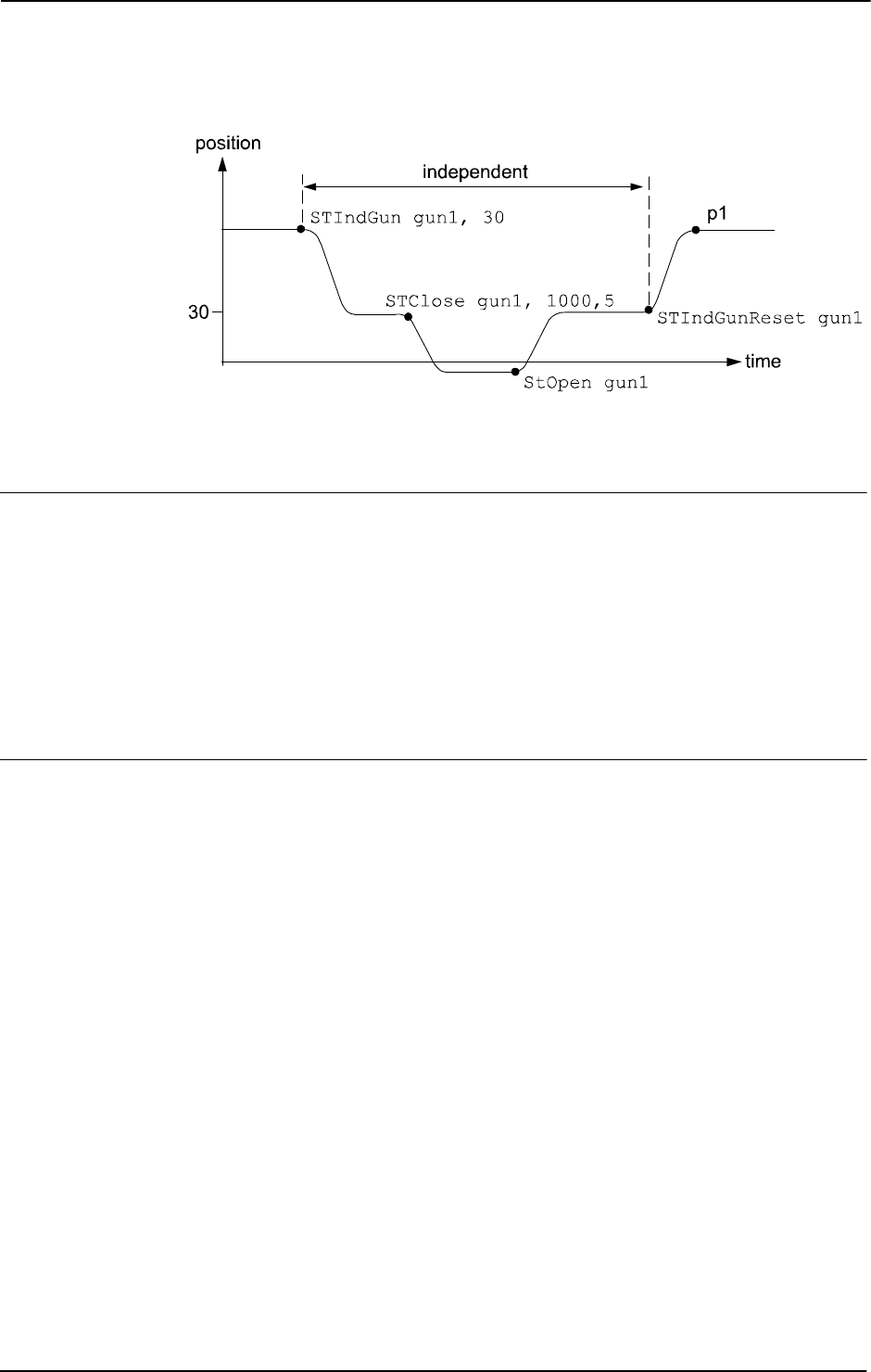
1 Instructions
1.179. STIndGun - Sets the gun in independent mode
Servo Tool Control
3HAC 16581-1 Revision: J502
© Copyright 2004-2010 ABB. All rights reserved.
xx0500002342
The position p1 depends on the position of the gun given in the robtarget just performed by
the robot.
Arguments
STIndGun ToolName GunPos
ToolName
Data type: string
The name of the mechanical unit.
GunPos
Data type: num
The position (stroke) of the servo gun in mm.
Syntax
STIndGun
[ ToolName ’:=’ ] < expression (IN) of string > ‘,’
[ GunPos ’:=’ < expression (IN) of num > ]’;’
Continued

1 Instructions
1.180. STIndGunReset - Resets the gun from independent mode
Servo Tool Control
5033HAC 16581-1 Revision: J
© Copyright 2004-2010 ABB. All rights reserved.
1.180. STIndGunReset - Resets the gun from independent mode
Usage
STIndGunReset (Servo Tool independent gun reset) is used to reset the gun from
independent mode and thereafter move the gun to current robtarget position.
Basic examples
Basic examples of the instruction
STIndGunReset are illustrated below.
STIndGunReset gun1;
Arguments
STIndGunReset ToolName
ToolName
Data type: string
The name of the mechanical unit.
Program execution
The instruction will reset the gun from independent mode and move the gun to current
robtarget position. During this movement the coordinated speed of the gun must be zero
otherwise an error will occur. The coordinated speed will be zero if the robot is standing still
or if the current robot movement includes a “zero movement” from the gun.
Syntax
STIndGunReset
[ToolName ´:=´]<expression (IN) of string>´;´
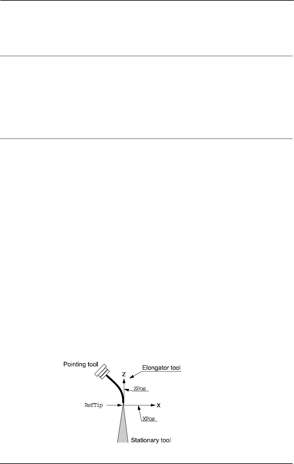
1 Instructions
1.181. SToolRotCalib - Calibration of TCP and rotation for stationary tool
RobotWare - OS
3HAC 16581-1 Revision: J504
© Copyright 2004-2010 ABB. All rights reserved.
1.181. SToolRotCalib - Calibration of TCP and rotation for stationary tool
Usage
SToolRotCalib (Stationary Tool Rotation Calibration) is used to calibrate the TCP and
rotation of a stationary tool.
The position of the robot and its movements are always related to its tool coordinate system,
i.e. the TCP and tool orientation. To get the best accuracy it is important to define the tool
coordinate system as correctly as possible.
The calibration can also be done with a manual method using the FlexPendant (described in
Operating manual - IRC5 with FlexPendant, section Programming and testing).
Description
To define the TCP and rotation of a stationary tool, you need a movable pointing tool mounted
on the end effector of the robot.
Before using the instruction
SToolRotCalib, some preconditions must be fulfilled:
• The stationary tool that is to be calibrated must be mounted stationary and defined
with the correct component robhold (
FALSE).
• The pointing tool (robhold TRUE) must be defined and calibrated with the correct
TCP values.
• If using the robot with absolute accuracy then the load and center of gravity for the
pointing tool should be defined.
LoadIdentify can be used for the load definition.
• The pointing tool, wobj0, and PDispOff must be activated before jogging the robot.
• Jog the TCP of the pointing tool as close as possible to the TCP of the stationary tool
(origin of the tool coordinate system) and define a
robtarget for the reference point
RefTip.
• Jog the robot without changing the tool orientation so the TCP of the pointing tool is
pointing at some point on the positive z-axis of the tool coordinate system, and define
a
robtarget for point ZPos.
• Jog the robot without changing the tool orientation so the TCP of the pointing tool is
pointing at some point on the positive x-axis of the tool coordinate system, and define
a
robtarget for point XPos.
As a help for pointing out the positive z-axis and x-axis, some type of elongator tool can be
used.
Definition of robtargets
RefTip, ZPos, and XPos. See figure below.
xx0500002343
Continues on next page

1 Instructions
1.181. SToolRotCalib - Calibration of TCP and rotation for stationary tool
RobotWare - OS
5053HAC 16581-1 Revision: J
© Copyright 2004-2010 ABB. All rights reserved.
NOTE!
It is not recommended to modify the positions
RefTip, ZPos, and XPos in the instruction
SToolRotCalib.
Basic examples
Basic examples of the instruction
SToolRotCalib are illustrated below.
Example 1
! Created with pointing TCP pointing at the stationary tool
! coordinate system
CONST robtarget pos_tip := [...];
CONST robtarget pos_z := [...];
CONST robtarget pos_x := [...];
PERS tooldata tool1:= [ FALSE, [[0, 0, 0], [1, 0, 0 ,0]], [0, [0,
0, 0], [1, 0, 0, 0], 0, 0, 0]];
!Instructions for creating or ModPos of pos_tip, pos_z and pos_x
MoveJ pos_tip, v10, fine, point_tool;
MoveJ pos_z, v10, fine, point_tool;
MoveJ pos_x, v10, fine, point_tool;
SToolRotCalib pos_tip, pos_z, pos_x, tool1;
The position of the TCP (tframe.trans) and the tool orientation (tframe.rot) of tool1
in the world coordinate system is calculated and updated.
Arguments
SToolRotCalib RefTip ZPos XPos Tool
RefTip
Data type: robtarget
The point where the TCP of the pointing tool is pointing at the stationary tool TCP to
calibrate.
ZPos
Data type: robtarget
The elongator point that defines the positive z direction.
XPos
Data type: robtarget
The elongator point that defines the positive x direction.
Tool
Data type: tooldata
The persistent variable of the tool that is to be calibrated.
Continued
Continues on next page

1 Instructions
1.181. SToolRotCalib - Calibration of TCP and rotation for stationary tool
RobotWare - OS
3HAC 16581-1 Revision: J506
© Copyright 2004-2010 ABB. All rights reserved.
Program execution
The system calculates and updates the TCP (
tframe.trans) and the tool orientation
(
tfame.rot) in the specified tooldata. The calculation is based on the specified 3
robtarget. The remaining data in tooldata is not changed.
Syntax
SToolRotCalib
[ RefTip ’:=’ ] < expression (IN) of robtarget > ’,’
[ ZPos ’:=’ ] < expression (IN) of robtarget > ’,’
[ XPos ’:=’ ] < expression (IN) of robtarget > ’,’
[ Tool ’:=’ ] < persistent (PERS) of tooldata > ’;’
Related information
For information about See
Calibration of TCP for a moving tool MToolTCPCalib - Calibration of TCP for moving
tool on page 278
Calibration of rotation for a moving tool MToolRotCalib - Calibration of rotation for moving
tool on page 275
Calibration of TCP for a stationary tool MToolTCPCalib - Calibration of TCP for moving
tool on page 278
Continued
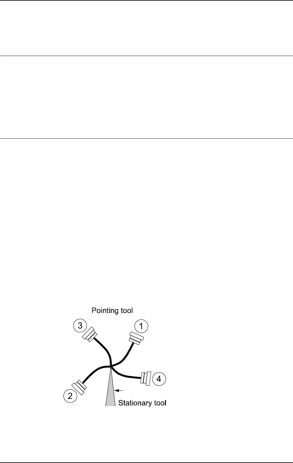
1 Instructions
1.182. SToolTCPCalib - Calibration of TCP for stationary tool
RobotWare - OS
5073HAC 16581-1 Revision: J
© Copyright 2004-2010 ABB. All rights reserved.
1.182. SToolTCPCalib - Calibration of TCP for stationary tool
Usage
SToolTCPCalib (Stationary Tool TCP Calibration) is used to calibrate the Tool Center Point
- TCP for a stationary tool.
The position of the robot and its movements are always related to its tool coordinate system,
i.e. the TCP and tool orientation. To get the best accuracy it is important to define the tool
coordinate system as correctly as possible.
The calibration can also be done with a manual method using the FlexPendant (described in
Operating manual - IRC5 with FlexPendant, section Programming and testing).
Description
To define the TCP of a stationary tool, you need a movable pointing tool mounted on the end
effector of the robot.
Before using the instruction
SToolTCPCalib, some preconditions must be fulfilled:
• The stationary tool that is to be calibrated must be mounted stationary and defined
with the correct component
robhold (FALSE).
• The pointing tool (robhold TRUE) must be defined and calibrated with the correct
TCP values.
• If using the robot with absolute accuracy then the load and center of gravity for the
pointing tool should be defined.
LoadIdentify can be used for the load definition.
• The pointing tool, wobj0 and PDispOff, must be activated before jogging the robot.
• Jog the TCP of the pointing tool as close as possible to the TCP of the stationary tool
and define a
robtarget for the first point p1.
• Define the further three positions p2, p3, and p4, all with different orientations.
• It is recommended that the TCP is pointed out with different orientations to obtain a
reliable statistical result. However, it is not necessary.
Definition of 4 robtargets p1...p4. See figure below.
xx0500002344
Continues on next page

1 Instructions
1.182. SToolTCPCalib - Calibration of TCP for stationary tool
RobotWare - OS
3HAC 16581-1 Revision: J508
© Copyright 2004-2010 ABB. All rights reserved.
NOTE!
It is not recommended to modify the positions
Pos1 to Pos4 in the instruction
SToolTCPCalib.
The reorientation between the 4 positions should be as big as possible, putting the robot in
different configurations.Its also good practice to check the quality of the TCP after a
calibration. Which can be performed by reorientation of the tool to check if the TCP is
standing still.
Basic example
Basic examples of the instruction
SToolTCPCalib are illustrated below.
Example 1
! Created with pointing TCP pointing at the stationary TCP
CONST robtarget p1 := [...];
CONST robtarget p2 := [...];
CONST robtarget p3 := [...];
CONST robtarget p4 := [...];
PERS tooldata tool1:= [ FALSE, [[0, 0, 0], [1, 0, 0 ,0]], [0,001,
[0, 0, 0.001], [1, 0, 0, 0], 0, 0, 0]];
VAR num max_err;
VAR num mean_err;
! Instructions for creating or ModPos of p1 - p4
MoveJ p1, v10, fine, point_tool;
MoveJ p2, v10, fine, point_tool;
MoveJ p3, v10, fine, point_tool;
MoveJ p4, v10, fine, point_tool;
SToolTCPCalib p1, p2, p3, p4, tool1, max_err, mean_err;
The TCP value (tframe.trans) of tool1 will be calibrated and updated. max_err and
mean_err will hold the max error in mm from the calculated TCP and the mean error in mm
from the calculated TCP, respectively.
Arguments
SToolTCPCalib Pos1 Pos2 Pos3 Pos4 Tool MaxErr MeanErr
Pos1
Data type: robtarget
The first approach point.
Pos2
Data type: robtarget
The second approach point.
Pos3
Data type: robtarget
The third approach point.
Continued
Continues on next page

1 Instructions
1.182. SToolTCPCalib - Calibration of TCP for stationary tool
RobotWare - OS
5093HAC 16581-1 Revision: J
© Copyright 2004-2010 ABB. All rights reserved.
Pos4
Data type: robtarget
The fourth approach point.
Tool
Data type: tooldata
The persistent variable of the tool that is to be calibrated.
MaxErr
Data type: num
The maximum error in mm for one approach point.
MeanErr
Data type: num
The average distance that the approach points are from the calculated TCP, i.e. how accurately
the robot was positioned relative to the stationary TCP.
Program execution
The system calculates and updates the TCP value in the world coordinate system
(tfame.trans) in the specified tooldata. The calculation is based on the specified 4
robtarget. The remaining data in tooldata, such as tool orientation (tframe.rot), is not
changed.
Syntax
SToolTCPCalib
[ Pos1 ’:=’ ] < expression (IN) of robtarget > ’,’
[ Pos2 ’:=’ ] < expression (IN) of robtarget > ’,’
[ Pos3 ’:=’ ] < expression (IN) of robtarget > ’,’
[ Pos4 ’:=’ ] < expression (IN) of robtarget > ’,’
[ Tool ’:=’ ] < persistent (PERS) of tooldata > ’,’
[ MaxErr ’:=’ ] < variable (VAR) of num > ’,’
[ MeanErr’ :=’ ] < variable (VAR) of num > ’;’
Related information
For information about See
Calibration of TCP for a moving tool SToolTCPCalib - Calibration of TCP for stationary
tool on page 507
Calibration of rotation for a moving tool MToolRotCalib - Calibration of rotation for moving
tool on page 275
Calibration of TCP and rotation for a
stationary tool
SToolRotCalib - Calibration of TCP and rotation
for stationary tool on page 504
Continued

1 Instructions
1.183. Stop - Stops program execution
RobotWare - OS
3HAC 16581-1 Revision: J510
© Copyright 2004-2010 ABB. All rights reserved.
1.183. Stop - Stops program execution
Usage
Stop is used to stop the program execution. Any movement performed at the time will be
finished before the
Stop instruction is ready.
Basic examples
Basic examples of the instruction
Stop are illustrated below.
See also More examples on page 512.
Example 1
TPWrite "The line to the host computer is broken";
Stop;
Program execution stops after a message has been written on the FlexPendant.
Arguments
Stop [ \NoRegain ] | [ \AllMoveTasks ]
[ \NoRegain ]
Data type: switch
Specifies for the next program start, whether or not the affected mechanical unit should return
to the stop position.
If the argument
\NoRegain is set then the robot and external axes will not return to the stop
position (if they have been jogged away from it).
If the argument is omitted and if the robot or external axes have been jogged away from the
stop position then the robot displays a question on the FlexPendant. The user can then answer
whether or not the robot should return to the stop position.
[ \AllMoveTasks ]
Data type: switch
Specifies that programs in all running normal tasks besides the actual task should be stopped.
If the argument is omitted then only the program in the task that executes the instruction will
be stopped.
Continues on next page

1 Instructions
1.183. Stop - Stops program execution
RobotWare - OS
5113HAC 16581-1 Revision: J
© Copyright 2004-2010 ABB. All rights reserved.
Program execution
The instruction stops program execution when the affected mechanical units in the actual
motion task have reached zero speed for the movement it is performing at the time, and stands
still. Program execution can then be restarted from the next instruction.
If the instruction is used without any switches then only the program in that task will be
affected.
If the
AllMoveTasks switch is used in a task (Normal, Static, or Semistatic) then the
program in that task and all normal tasks will stop. See more about declaration of tasks in
documentation for System Parameters
The
NoRegain switch is only possible to use in motion tasks since it only concerns the
motion path.
If there is a
Stop instruction in some event routine then the execution of the routine will be
stopped, and the execution continue as described in TABLE 1.
If there is a
Stop\AllMoveTasks instruction in some event routine in a MultiMove
system, then the task containing the instruction continue as described in TABLE 1 and all
other motion tasks executing an event routine continues as described in TABLE 2 (same
affect as for normal program stop during execution of the event routine).
TABLE 1
Event routines Affect by Stop instruction
POWER ON The execution is stopped. STOP event
routines are executed. The execution does not
continue in the event routine at the next start
order..
START The execution is stopped. STOP event
routines are executed. The execution does not
continue in the event routine at the next start
order.
RESTART The execution is stopped. STOP event routines
are executed. The execution does not
continue in the event routine at the next start
order.
STOP The execution is stopped. No other event
routines are executed. The execution does not
continue in the event routine at the next start
order.
QSTOP The execution is stopped. STOP event routines
are executed. The execution does not
continue in the event routine at the next start
order.
RESET The execution is stopped. STOP event routines
are executed. The execution does not
continue in the event routine at the next start
order.
Continued
Continues on next page

1 Instructions
1.183. Stop - Stops program execution
RobotWare - OS
3HAC 16581-1 Revision: J512
© Copyright 2004-2010 ABB. All rights reserved.
More examples
More examples of how to use the instruction
Stop are illustrated below.
Example 1
MoveL p1, v500, fine, tool1;
TPWrite "Jog the robot to the position for pallet corner 1";
Stop \NoRegain;
p1_read := CRobT(\Tool:=tool1 \WObj:=wobj0);
MoveL p2, v500, z50, tool1;
Program execution stops with the robot at p1. The operator jogs the robot to p1_read. For
the next program start the robot does not regain to
p1, so the position p1_read can be stored
in the program.
Syntax
Stop
[ ’\’ NoRegain ]’|’
[ ’\’ AllMoveTasks ]’;’
Related information
TABLE 2
Event routines Affect by Stop \AllMoveTasks
POWER ON The POWER ON event routine completes its
execution. No STOP event routines are
executed.
START The execution is stopped, and continues at the
next ordered start. No STOP event routines
are executed.
RESTART The execution is stopped, and continues at the
next ordered start. No STOP event routines are
executed.
STOP The STOP event routine completes its
execution.
QSTOP The QSTOP event routine completes its
execution.
RESET The execution is stopped, and continues at the
next ordered start. No STOP event routines are
executed.
For information about See
Terminating program execution EXIT - Terminates program execution on page
105
Only stopping robot movements StopMove - Stops robot movement on page
515
Stop program for debugging Break - Break program execution on page 32
Continued

1 Instructions
1.184. STOpen - Open a Servo Tool
Servo Tool Control
5133HAC 16581-1 Revision: J
© Copyright 2004-2010 ABB. All rights reserved.
1.184. STOpen - Open a Servo Tool
Usage
STOpen is used to open the Servo Tool.
Basic examples
Basic examples of the instruction
STOpen are illustrated below.
Example 1
STOpen gun1;
Open the servo tool gun1. Wait until the gun is opened before continuing with the next Rapid
instruction.
Example 2
STOpen gun1 \Conc;
Open the servo tool gun1. Continue with the next Rapid instruction without waiting for the
gun to be opened.
Example 3
STOpen "SERVOGUN"\WaitZeroSpeed;
Stop the servo tool SERVOGUN, wait until any coordinated movement has finished, and then
open the servo tool
SERVOGUN.
Arguments
STOpen ToolName
ToolName
Data type: string
The name of the mechanical unit.
[\WaitZeroSpeed]
Data type: switch
Stop the servo tool, wait until any coordinated movement has finished, and then open the
servo tool.
[\Conc]
Data type: switch
Subsequent instructions are executed while the gun is moving. The argument can be used to
shorten cycle time. This is useful when, for example, two guns are controlled at the same
time.
Continues on next page

1 Instructions
1.184. STOpen - Open a Servo Tool
Servo Tool Control
3HAC 16581-1 Revision: J514
© Copyright 2004-2010 ABB. All rights reserved.
Program execution
If the mechanical unit exists then the servo tool is ordered to open. The tip force is reduced
to zero and the tool arm is moved back to the pre_close position.
The tool arm is moved with max speed and acceleration as it is defined in the system
parameters for the corresponding external axis. As for other axes movements, the speed is
reduced in manual mode.
It is possible to open the tool during a programmed robot movement as long as the robot
movement does not include a movement of the tool arm. If the tool is opened during such
movement then an error
50251 Tool opening failed will be displayed. The switch
WaitZeroSpeed can be used to reduce the risk for this error.
If the switch Conc is used then the instruction will be considered to be ready before the servo
tool is opened. It is recommended that the function
STIsOpen is used after STOpen to avoid
any problems in concurrent mode.
For more details, see Servo tool motion control.
Error handling
If the specified servo tool name is not a configured servo tool then the system variable
ERRNO
is set to
ERR_NO_SGUN.
If the servo tool mechanical unit is not activated then the system variable
ERRNO is set to
ERR_SGUN_NOTACT. Use instruction ActUnit to activate the servo tool.
If the servo tool position is not initialized then the system variable
ERRNO is set to
ERR_SGUN_NOTINIT. The servo tool position must be initialized the first time the gun is
installed or after a fine calibration is made. Use the service routine
ManServiceCalib, or
perform a tip change calibration. The tip wear will be reset.
If the servo tool tips are not synchronized then the system variable
ERRNO is set to
ERR_SGUN_NOTSYNC. The servo tool tips must be synchronized if the revolution counter has
been lost and/or updated. No process data such as tip wear will be lost.
All above errors can be handled in a RAPID error handler.
NOTE!
If the instruction is invoked from a background task and there is an emergency stop then the
instruction will be finished without an error.
Syntax
STOpen
[ ’ToolName ’:=’ ] < expression (IN) of string > ‘,’
[ ’\’WaitZeroSpeed]‘ ,’
[’\’Conc]’
Related information
For information about See
Close a servo tool STClose - Close a Servo Tool on page 496
Continued

1 Instructions
1.185. StopMove - Stops robot movement
RobotWare - OS
5153HAC 16581-1 Revision: J
© Copyright 2004-2010 ABB. All rights reserved.
1.185. StopMove - Stops robot movement
Usage
StopMove is used to stop robot and external axes movements and any belonging process
temporarily. If the instruction
StartMove is given then the movement and process resumes.
This instruction can, for example, be used in a trap routine to stop the robot temporarily when
an interrupt occurs.
For base system it is possible to use this instruction in the following type of program tasks:
• main task T_ROB1 for stopping the movement in that task.
• any other task for stopping the movements in the main task.
For MultiMove systems it is possible to use this instruction in following type of program
tasks:
• motion task for stopping the movement in that task.
• non-motion task for stopping the movement in the connected motion task. Besides
that, if movement is stopped in one motion task belonging to a coordinated
synchronized task group then the movement is stopped in all the cooperated tasks.
Basic examples
Basic examples of the instruction
StopMove are illustrated below.
See also More examples on page 517.
Example 1
StopMove;
WaitDI ready_input, 1;
StartMove;
The robot movement is stopped until the input, ready_input is set.
Arguments
StopMove [\Quick] [\AllMotionTasks]
[\Quick]
Data type: switch
Stops the robot on the path as fast as possible.
Without the optional parameter
\Quick, the robot stops on the path, but the braking distance
is longer (same as for normal Program Stop).
[\AllMotionTasks]
Data type: switch
Stop the movement of all mechanical units in the system. The switch [\AllMotionTasks]
can only be used from a non-motion program task.
Continues on next page

1 Instructions
1.185. StopMove - Stops robot movement
RobotWare - OS
3HAC 16581-1 Revision: J516
© Copyright 2004-2010 ABB. All rights reserved.
Program execution
The movements of the robot and external axes stop without the brakes being engaged. Any
processes associated with the movement in progress are stopped at the same time as the
movement is stopped.
Program execution continues after waiting for the robot and external axes to stop (standing
still).
With the switch
\AllMotionTasks (only allowed from non-motion program task) the
movements for all mechanical units in the system are stopped.
In a base system without the switch
\AllMotionTasks, the movements for the following
mechanical units are stopped:
• always the mechanical units in the main task, independent of which task executes the
StopMove instruction.
In a MultiMove system without the switch
\AllMotionTasks, the movements for the
following mechanical units are stopped:
• the mechanical units in the motion task executing StopMove.
• the mechanical units in the motion task that are connected to the non-motion task
executing
StopMove. Besides that, if mechanical units are stopped in one connected
motion task belonging to a coordinated synchronized task group then the mechanical
units are stopped in all the cooperated tasks.
The
StopMove state in the motion task generated from the motion task itself will
automatically be reset when starting that task from the beginning.
The
StopMove state in connected motion task, generated from the some non-motion task,
will automatically be reset:
• if normal non-motion task, at the start of that task from the beginning.
• if semi-static non-motion task, at power fail restart when the task is starting from the
beginning.
• if static non-motion task, at installation start when the task is starting from the
beginning.
Continued
Continues on next page

1 Instructions
1.185. StopMove - Stops robot movement
RobotWare - OS
5173HAC 16581-1 Revision: J
© Copyright 2004-2010 ABB. All rights reserved.
More examples
More examples of the instruction
StopMove are illustrated below.
Example 1
VAR intnum intno1;
...
CONNECT intno1 WITH go_to_home_pos;
ISignalDI di1,1,intno1;
TRAP go_to_home_pos
VAR robtarget p10;
StopMove;
StorePath;
p10:=CRobT(\Tool:=tool1 \WObj:=wobj0);
MoveL home,v500,fine,tool1;
WaitDI di1,0;
Move L p10,v500,fine,tool1;
RestoPath;
StartMove;
ENDTRAP
When the input di1 is set to 1 an interrupt is activated which in turn activates the interrupt
routine
go_to_home_pos. The current movement is stopped, and the robot moves instead to
the
home position. When di1 is set to 0 the robot returns to the position at which the interrupt
occurred and continues to move along the programmed path.
Example 2
VAR intnum intno1;
...
CONNECT intno1 WITH go_to_home_pos;
ISignalDI di1,1,intno1;
TRAP go_to_home_pos ()
VAR robtarget p10;
StorePath;
p10:=CRobT(\Tool:=tool1 \WObj:=wobj0);
MoveL home,v500,fine,tool1;
WaitDI di1,0;
MoveL p10,v500,fine,tool1;
RestoPath;
StartMove;
ENDTRAP
Similar to the previous example but the robot does not move to the home position until the
current movement instruction is finished.
Limitations
Only one of several non-motion tasks is allowed at the same time to do
StopMove -
StartMove sequence against some motion task.
Continued
Continues on next page

1 Instructions
1.185. StopMove - Stops robot movement
RobotWare - OS
3HAC 16581-1 Revision: J518
© Copyright 2004-2010 ABB. All rights reserved.
Syntax
StopMove
[’\’Quick]
[’\’AllMotionTasks]’;’
Related information
For information about See
Continuing a movement StartMove - Restarts robot movement on page 486
StartMoveRetry - Restarts robot movement and
execution on page 489
Store - restore path StorePath - Stores the path when an interrupt occurs
on page 521
RestoPath - Restores the path after an interrupt on
page 362
Continued

1 Instructions
1.186. StopMoveReset - Reset the system stop move state
RobotWare - OS
5193HAC 16581-1 Revision: J
© Copyright 2004-2010 ABB. All rights reserved.
1.186. StopMoveReset - Reset the system stop move state
Usage
StopMoveReset is used to reset the system stop move state without starting any movements.
Asynchronously raised movements errors, such as
ERR_PATH_STOP or specific process error
during the movements, can be handled in the
ERROR handler. When such an error occurs the
movements are stopped at once, and the system stop move flag is set for actual program tasks.
This means that the movement is not restarted if doing any program start while program
pointer is inside the
ERROR handler.
Restart of the movements after such movement error will be done after one of these action:
• Execute StartMove or StartMoveRetry.
• Execute StopMoveReset and the movement will restart at the next program start.
Basic examples
Basic examples of the instruction
StopMoveReset are illustrated below.
Example 1
...
ArcL p101, v100, seam1, weld1, weave1, z10, gun1;
...
ERROR
IF ERRNO=AW_WELD_ERR OR ERRNO=ERR_PATH_STOP THEN
! Execute something but without any restart of the movement
! ProgStop - ProgStart must be allowed
...
! No idea to try to recover from this error, so let the error
! stop the program
...
! Reset the move stop flag, so it’s possible to manual restart
! the program and the movement after that the program has
! stopped
StopMoveReset;
ENDIF
ENDPROC
After that above ERROR handler has executed the ENDPROC, the program execution stops and
the pointer is at the beginning of the
ArcL instruction. Next program start restarts the program
and movement from the position where the original movement error occurred.
Arguments
StopMoveReset [\AllMotionTasks]
[\AllMotionTasks]
Data type: switch
Reset the system stop move state for all mechanical units in the system. The switch
[\AllMotionTasks] can only be used from a non-motion program task.
Continues on next page

1 Instructions
1.186. StopMoveReset - Reset the system stop move state
RobotWare - OS
3HAC 16581-1 Revision: J520
© Copyright 2004-2010 ABB. All rights reserved.
Program execution
To reset a MultiMove application in synchronized coordinated mode,
StopMoveReset must
be executed in all motion tasks that are involved in coordination.
With the switch
\AllMotionTasks (only allowed from non-motion program task) the reset
is done for all all mechanical units in the system.
In a base system without the switch
\AllMotionTasks, the reset is always done for the main
task, independent of which task that executes the
StopMoveReset instruction.
For base system it is possible to use
StopMoveReset in the following type of program tasks:
• main task T_ROB1 to reset the stop move state in that task.
• any other task to reset the stop move state in the main task.
For MultiMove system it is possible to use this instruction in the following type of program
tasks:
• motion task, to reset the stop move state in that task.
• non motion task, to reset the stop move state in the connected motion task. Besides
that, if the reset of the stop move state in one connected motion task belonging to a
coordinated synchronized task group, the stop move state is reset in all the cooperating
tasks.
Syntax
StopMoveReset
[’\’AllMotionTasks]’;’
Related information
For information about See
Stop the movement StopMove - Stops robot movement on page 515
Continuing a movement StartMove - Restarts robot movement on page
486
StartMoveRetry - Restarts robot movement and
execution on page 489
Store - restore path StorePath - Stores the path when an interrupt
occurs on page 521
RestoPath - Restores the path after an interrupt
on page 362
Continued

1 Instructions
1.187. StorePath - Stores the path when an interrupt occurs
RobotWare - OS
5213HAC 16581-1 Revision: J
© Copyright 2004-2010 ABB. All rights reserved.
1.187. StorePath - Stores the path when an interrupt occurs
Usage
StorePath is used to store the movement path being executed, e.g. when an error or interrupt
occurs. The error handler or a trap routine can then start a new temporary movement and
finally restart the original movement that was stored earlier.
For example, this instruction can be used to go to a service position or to clean the gun when
an error occurs.
This instruction can only be used in the main task
T_ROB1 or, if in a MultiMove system, in
Motion tasks.
Basic examples
Basic examples of the instruction
StorePath are illustrated below.
See also More examples on page 522.
Example 1
StorePath;
The current movement path is stored for later use. Set the system to independent movement
mode.
Example 2
StorePath \KeepSync;
The current movement path is stored for later use. Keep synchronized movement mode.
Arguments
StorePath [\KeepSync]
[\KeepSync]
Keep Synchronization
Data type:
switch
Keeps synchronized movement mode after the StorePath \KeepSync. The KeepSync
switch can only be used if the system is in synchronized movement mode before the
StorePath \KeepSync
call.
Without the optional parameter
\KeepSync, in a MultiMove coordinated synchronized
system, the system is set to independent-semicoordinated movement mode. After execution
of
StorePath in all involved tasks, the system is in semicoordinated mode if further on use
of coordinated work object. Otherwise it is in independent mode. If in semicoordinated mode
it is recommended to always start with a movement in the mechanical unit that controls the
user frame before
WaitSyncTask in all involved tasks.
Program execution
The current movement path of the robot and external axes are saved. After this, another
movement can be started in a trap routine or in an error handler. When the reason for the error
or interrupt has been rectified then the saved movement path can be restarted.
Continues on next page

1 Instructions
1.187. StorePath - Stores the path when an interrupt occurs
RobotWare - OS
3HAC 16581-1 Revision: J522
© Copyright 2004-2010 ABB. All rights reserved.
More examples
More examples of how to use the instruction
StorePath are illustrated below.
Example 1
TRAP machine_ready
VAR robtarget p1;
StorePath;
p1 := CRobT();
MoveL p100, v100, fine, tool1;
...
MoveL p1, v100, fine, tool1;
RestoPath;
StartMove;
ENDTRAP
When an interrupt occurs that activates the trap routine machine_ready, the movement path
which the robot is executing at the time is stopped at the end of the instruction (ToPoint) and
stored. After this the robot remedies the interrupt by, for example, replacing a part in the
machine. Then the normal movement is restarted.
Limitations
Only the movement path data is stored with the instruction
StorePath.
If the user wants to order movements on the new path level then the actual stop position must
be stored directly after
StorePath and before RestoPath makes a movement to the stored
stop position on the path.
Only one movement path can be stored at a time.
Syntax
StorePath
[’\’KeepSync]’;’
Related information
For information about See
Restoring a path RestoPath - Restores the path after an interrupt on page
362
More examples RestoPath - Restores the path after an interrupt on page
362
PathRecStart - Start the path recorder on page 308
SyncMoveResume - Set synchronized coordinated
movements on page 541
SyncMoveSuspend - Set independent-semicoordinated
movements on page 543
Continued

1 Instructions
1.188. STTune - Tuning Servo Tool
Servo Tool Control
5233HAC 16581-1 Revision: J
© Copyright 2004-2010 ABB. All rights reserved.
1.188. STTune - Tuning Servo Tool
Usage
STTune is used to tune/change a servo tool parameter. The parameter is changed temporarily
from the original value, which is set up in the system parameters. The new tune value will be
active immediately after executing the instruction.
STTune is useful in tuning procedures. A tuning procedure is typically used to find an optimal
value for a parameter. An experiment (i.e. a program execution with a servo tool movement)
is repeated when using different parameter tune values.
STTune shall not be used during calibration or tool closure.
Basic examples
Basic examples of the instruction
STTune are illustrated below.
Example 1
STTune SEOLO_RG, 0.050, CloseTimeAdjust;
The servo tool parameter CloseTimeAdjust is temporarily set to 0.050 seconds.
Arguments
STTune MecUnit TuneValue Type
MecUnit
Data type: mecunit
The name of the mechanical unit.
TuneValue
Data type: num
New tuning value.
Type
Data type: tunegtype
Parameter type. Servo tool parameters available for tuning are RampTorqRefOpen,
RampTorqRefClose, KV, SpeedLimit, CollAlarmTorq, CollContactPos,
CollisionSpeed, CloseTimeAdjust, ForceReadyDelayT, PostSyncTime,
CalibTime, CalibForceLow, CalibForceHigh. These types are predefined in the system
parameters and defines the original values.
Description
RampTorqRefOpen
Tunes the system parameter Ramp when decrease force, which decides how fast force
is released while opening the tool. The unit is Nm/s and a typical value 200.
Corresponding system parameter: topic Motion, type Force master, parameter
ramp_torque_ref_opening.
Continues on next page

1 Instructions
1.188. STTune - Tuning Servo Tool
Servo Tool Control
3HAC 16581-1 Revision: J524
© Copyright 2004-2010 ABB. All rights reserved.
RampTorqRefClose
Tunes the system parameter Ramp when increase force, which decides how fast force
is built up while opening the tool. The unit is Nm/s and a typical value 80.
Corresponding system parameter: topic Motion, type Force master, parameter
ramp_torque_ref_closing.
KV
Tunes the system parameter KV, which is used for speed limitation. The unit is Nms/rad and
a typical value 1. For more details, see the external axis documentation.
Corresponding system parameter: topic Motion, type Force master, parameter
Kv.
SpeedLimit
Tunes the system parameter Speed limit, which is used for speed limitation. The unit is
rad/s (motor speed) and a typical value 60. For more details, see the external axis
documentation.
Corresponding system parameter: topic Motion, type Force master, parameter
speed_limit.
CollAlarmTorq
Tunes the system parameter Collision alarm torque, which is used for the automatic
calibration of new tips. The unit is Nm (motor torque) and a typical value 1. For more details,
see the external axis documentation.
Corresponding system parameter: topic Motion, type Force master, parameter
alarm_torque.
CollContactPos
Tunes the system parameter Collision delta pos, which is used for automatic calibration
of new tips. The unit is m and a typical value 0,002. For more details, see the external axis
documentation.
Corresponding system parameter: topic Motion, type Force master, parameter
distance_to_contact_position.
CollisionSpeed
Tunes the system parameter Collision speed, which is used for automatic calibration of
new tips. The unit is m/s and a typical value 0,02. For more details, see the external axis
documentation.
Corresponding system parameter: topic Motion, type Force master, parameter
col_speed.
CloseTimeAdjust
Constant time adjustment (s), positive or negative, of the moment when the tool tips reaches
contact during a tool closure. May be used to delay the closing slightly when the synchronized
pre-closing is used for welding.
Corresponding system parameter: topic Motion, type SG process, parameter
min_close_time_adjust.
Continued
Continues on next page

1 Instructions
1.188. STTune - Tuning Servo Tool
Servo Tool Control
5253HAC 16581-1 Revision: J
© Copyright 2004-2010 ABB. All rights reserved.
ForceReadyDelayT
Constant time delay (s) before sending the weld ready signal after reaching the programmed
force.
Corresponding system parameter: topic Motion, type SG process, parameter
pre_sync_delay_time.
PostSyncTime
Release time anticipation (s) of the next robot movement after a weld. This tune type can be
tuned to synchronize the gun opening with the next robot movement. The synchronization
may fail if the parameters is set too high.
Corresponding system parameter: topic Motion, type SG process, parameter
post_sync_time.
CalibTime
The wait time (s) during a calibration before the positional tool tip correction is done. For best
results do not use too low a value like 0.5 s.
Corresponding system parameter: topic Motion, type SG process, parameter
calib_time.
CalibForceLow
The minimum tip force (N) used during a TipWear calibration. For best result of the thickness
detection it is recommended to use the minimum programmed weld force.
Corresponding system parameter: topic Motion, type SG process, parameter
calib_force_low.
CalibForceHigh
The maximum tip force (N) used during a TipWear calibration. For best result of the thickness
detection it is recommended to use the max programmed weld force.
Corresponding system parameter: topic Motion, type SG process, parameter
calib_force_high.
Program execution
The specified tuning type and tuning value are activated for the specified mechanical unit.
This value is applicable for all movements until a new value is programmed for the current
mechanical unit or until the tuning types and values are reset using the instruction
STTuneReset.
The original tune values may be permanently changed in the system parameters.
The default servo tool tuning values are automatically set
• by executing instruction STTuneReset.
• at a cold start-up.
• when a new program is loaded.
• when starting program execution from the beginning.
Error handling
If the specified servo tool name is not a configured servo tool then the system variable
ERRNO
is set to
ERR_NO_SGUN.
The error can be handled in a Rapid error handler.
Continued
Continues on next page

1 Instructions
1.188. STTune - Tuning Servo Tool
Servo Tool Control
3HAC 16581-1 Revision: J526
© Copyright 2004-2010 ABB. All rights reserved.
Syntax
STTune
[ MecUnit ’:=’ ] < variable (VAR) of mecunit > ‘,’
[ TuneValue’ :=’ ] < expression (IN) of num > ‘,’
[ ’Type ’:=’] < expression (IN) of tunegtype > ]’;’
Related information
For information about See
Restore of servo tool parameters TuneReset - Resetting servo tuning on page 637
Tuning of servo tool Application manual - Additional axes and stand
alone controller
Continued

1 Instructions
1.189. STTuneReset - Resetting Servo tool tuning
Servo Tool Control
5273HAC 16581-1 Revision: J
© Copyright 2004-2010 ABB. All rights reserved.
1.189. STTuneReset - Resetting Servo tool tuning
Usage
STTuneReset is used to restore original values of servo tool parameters if they have been
changed by the
STTune instruction.
Basic examples
Basic examples of the instruction
STTuneReset are illustrated below.
Example 1
STTuneReset SEOLO_RG;
Restore original values of servo tool parameters for the mechanical unit SEOLO_RG.
Arguments
STTuneReset MecUnit
MecUnit
Data type: mecunit
The name of the mechanical unit.
Program execution
The original servo tool parameters are restored.
This is also achieved
• at a cold start-up.
• when a new program is loaded.
• when starting program execution from the beginning.
Error handling
If the specified servo tool name is not a configured servo tool then the system variable
ERRNO
is set to
ERR_NO_SGUN.
The error can be handled in a Rapid error handler.
Syntax
STTuneReset
[ MecUnit ’:=’ ] < variable (VAR) of mecunit > ‘,’
Related information
For information about See
Tuning of servo tool parameters STTune - Tuning Servo Tool on page 523
Tuning of servo tool parameters Application manual - Additional axes and stand
alone controller

1 Instructions
1.190. SyncMoveOff - End coordinated synchronized movements
RW-MRS Synchronized
3HAC 16581-1 Revision: J528
© Copyright 2004-2010 ABB. All rights reserved.
1.190. SyncMoveOff - End coordinated synchronized movements
Usage
SyncMoveOff is used to end a sequence of synchronized movements and, in most cases,
coordinated movements. First, all involved program tasks will wait to synchronize in a stop
point, and then the motion planners for the involved program tasks are set to independent
mode.
The instruction
SyncMoveOff can only be used in a MultiMove system with option
Coordinated Robots and only in program tasks defined as
Motion Task.
WARNING!
To reach safe synchronization functionality every meeting point (parameter
SyncID) must
have a unique name. The name of the meeting point must also be the same for all the program
tasks that should meet.
Basic examples
Basic examples of the instruction
SyncMoveOff are illustrated below.
See also More examples on page 530.
Example 1
!Program example in task T_ROB1
PERS tasks task_list{2} := [ ["T_ROB1"], ["T_ROB2"] ];
VAR syncident sync1;
VAR syncident sync2;
...
SyncMoveOn sync1, task_list;
...
SyncMoveOff sync2;
...
!Program example in task T_ROB2
PERS tasks task_list{2} := [ ["T_ROB1"], ["T_ROB2"] ];
VAR syncident sync1;
VAR syncident sync2;
...
SyncMoveOn sync1, task_list;
...
SyncMoveOff sync2;
...
The program task that first reaches SyncMoveOff with identity sync2 waits until the other
tasks reach
SyncMoveOff with the same identity sync2. At that synchronization point
sync2, the motion planners for the involved program tasks are set to independent mode.
After that, both task
T_ROB1 and T_ROB2 continue their execution.
Continues on next page

1 Instructions
1.190. SyncMoveOff - End coordinated synchronized movements
RW-MRS Synchronized
5293HAC 16581-1 Revision: J
© Copyright 2004-2010 ABB. All rights reserved.
Arguments
SyncMoveOff SyncID [\TimeOut]
SyncID
Synchronization Identity
Data type:
syncident
Variables that specify the name of the unsynchronization (meeting) point. Data type
syncident
is a non-value type. It is only used as an identifier for naming the
unsynchronization point.
The variable must be defined and have an equal name in all cooperated program tasks. It is
recommended to always define the variable global in each task (
VAR syncident ...).
[\TimeOut]
Data type: num
The max. time to wait for the other program tasks to reach the unsynchronization point. The
time-out is defined in seconds (resolution 0,001s).
If this time runs out before all program tasks have reached the unsynchronization point then
the error handler will be called, if there is one, with the error code
ERR_SYNCMOVEOFF. If
there is no error handler then the execution will be stopped.
If this argument is omitted then the program task will wait forever.
Program execution
The program task that first reaches
SyncMoveOff waits until all other specified tasks reach
SyncMoveOff with the same SyncID identity. At that SyncID unsynchronization point the
motion planner for the involved program tasks is set to independent mode. After that,
involved program tasks continue their execution.
The motion planner for the involved program tasks are set to unsynchronized mode. This
means the following:
• All RAPID program tasks and all movements from these tasks are working
independently of each other again.
• Any move instruction must not be marked with any ID number. See instruction
MoveL.
It is possible to exclude program tasks for testing purpose from FlexPendant - Task Selection
Panel. The instructions
SyncMoveOn and SyncMoveOff will still work with the reduced
number of program tasks, even for only one program task.
Continued
Continues on next page

1 Instructions
1.190. SyncMoveOff - End coordinated synchronized movements
RW-MRS Synchronized
3HAC 16581-1 Revision: J530
© Copyright 2004-2010 ABB. All rights reserved.
More examples
More examples of how to use the instruction
SyncMoveOff are illustrated below.
Example 1
!Program example in task T_ROB1
PERS tasks task_list{2} := [ ["T_ROB1"], ["T_ROB2"] ];
VAR syncident sync1;
VAR syncident sync2;
VAR syncident sync3;
PROC main()
...
MoveL p_zone, vmax, z50, tcp1;
WaitSyncTask sync1, task_list;
MoveL p_fine, v1000, fine, tcp1;
syncmove;
...
ENDPROC
PROC syncmove()
SyncMoveOn sync2, task_list;
MoveL * \ID:=10, v100, z10, tcp1 \WOBJ:= rob2_obj;
MoveL * \ID:=20, v100, fine, tcp1 \WOBJ:= rob2_obj;
SyncMoveOff sync3;
UNDO
SyncMoveUndo;
ENDPROC
!Program example in task T_ROB2
PERS tasks task_list{2} := [ ["T_ROB1"], ["T_ROB2"] ];
VAR syncident sync1;
VAR syncident sync2;
VAR syncident sync3;
PROC main()
...
MoveL p_zone, vmax, z50, obj2;
WaitSyncTask sync1, task_list;
MoveL p_fine, v1000, fine, obj2;
syncmove;
...
ENDPROC
Continued
Continues on next page

1 Instructions
1.190. SyncMoveOff - End coordinated synchronized movements
RW-MRS Synchronized
5313HAC 16581-1 Revision: J
© Copyright 2004-2010 ABB. All rights reserved.
PROC syncmove()
SyncMoveOn sync2, task_list;
MoveL * \ID:=10, v100, z10, obj2;
MoveL * \ID:=20, v100, fine, obj2 ;
SyncMoveOff sync3;
UNDO
SyncMoveUndo;
ENDPROC
First program tasks T_ROB1 and T_ROB2 are waiting at WaitSyncTask with identity sync1
for each other, programmed with corner path for the preceding movements for saving cycle
time.
Then the program tasks are waiting at
SyncMoveOn with identity sync2 for each other,
programmed with a necessary stop point for the preceding movements. After that, the motion
planner for the involved program tasks is set to synchronized mode.
After that,
T_ROB2 is moving the obj2 to ID point 10 and 20 in world coordinate system
while
T_ROB1 is moving the tcp1 to ID point 10 and 20 on the moving object obj2.
Then the program tasks are waiting at
SyncMoveOff with identity sync3 for each other,
programmed with a necessary stop point for the preceding movements. After that, the motion
planner for the involved program tasks is set to independent mode.
Example 2
!Program example with use of time-out function
VAR syncident sync3;
...
SyncMoveOff sync3 \TimeOut := 60;
...
ERROR
IF ERRNO = ERR_SYNCMOVEOFF THEN
RETRY;
ENDIF
The program task waits for an instruction SyncMoveOff and for some other program task to
reach the same synchronization point
sync3. After waiting 60 seconds, the error handler is
called with
ERRNO equal to ERR_SYNCMOVEOFF. Then the instruction SyncMoveOff is
called again for an additional wait of 60 seconds.
Continued
Continues on next page

1 Instructions
1.190. SyncMoveOff - End coordinated synchronized movements
RW-MRS Synchronized
3HAC 16581-1 Revision: J532
© Copyright 2004-2010 ABB. All rights reserved.
Example 3
!Example with with semicoordinated and syncronized movement
!Program example in task T_ROB1
PERS tasks task_list{2} := [ ["T_ROB1"], ["T_ROB2"] ];
VAR syncident sync1;
VAR syncident sync2;
..
PROC main()
...
MoveL p1_90, v100, fine, tcp1 \WOBJ:= rob2_obj;
WaitSyncTask sync1, task_list;
SyncMoveOn sync2, task_list;
MoveL p1_100 \ID:=10, v100, fine, tcp1 \WOBJ:= rob2_obj;
SyncMoveOff sync3;
WaitSyncTask sync3, task_list;
MoveL p1_120, v100, z10, tcp1 \WOBJ:= rob2_obj;
MoveL p1_130, v100, fine, tcp1 \WOBJ:= rob2_obj;
WaitSyncTask sync4, task_list;
...
ENDPROC
!Program example in task T_ROB2
PERS tasks task_list{2} := [ ["T_ROB1"], ["T_ROB2"] ];
VAR syncident sync1;
VAR syncident sync2;
..
PROC main()
...
MoveL p_fine, v1000, fine, tcp2;
WaitSyncTask sync1, task_list;
SyncMoveOn sync2, task_list;
MoveL p2_100 \ID:=10, v100, fine, tcp2;
SyncMoveOff sync3;
MoveL p2_100, v100, fine, tcp2;
WaitSyncTask sync3, task_list;
WaitSyncTask sync4, task_list;
MoveL p2_110, v100, z10, tcp2;
...
ENDPROC
When switching between semicoordinated to syncronized movement, a WaitSyncTask is
needed (when using identity
sync1).
When switching between syncronized to semicoordinated movement, the task that move the
work object (
rob2_obj) needs to move to the desired position. After that a WaitSyncTask
is needed (identity
sync3) before the semicoordinated movement.
Continued
Continues on next page

1 Instructions
1.190. SyncMoveOff - End coordinated synchronized movements
RW-MRS Synchronized
5333HAC 16581-1 Revision: J
© Copyright 2004-2010 ABB. All rights reserved.
Error handling
If time-out is reached because
SyncMoveOff is not ready in time then the system variable
ERRNO is set to ERR_SYNCMOVEOFF.
This error can be handled in the
ERROR handler.
Limitations
The
SyncMoveOff instruction can only be executed if all involved robots stand still in a stop
point.
If this instruction is preceded by a move instruction then that move instruction must be
programmed with a stop point (zonedata
fine), not a fly-by point. Otherwise restart after
power failure will not be possible.
SyncMoveOff cannot be executed in a RAPID routine connected to any of the following
special system events: PowerOn, Stop, QStop, Restart, Reset, or Step.
Syntax
SyncMoveOff
[ SyncID ’:=’ ] < variable (VAR) of syncident>
[ ’\’TimeOut’ :=’ < expression (IN) of num> ] ’;’
Related information
For information about See
Specify cooperated program tasks tasks - RAPID program tasks on page 1204
Identity for synchronization point syncident - Identity for synchronization point
on page 1200
Start coordinated synchronized movements SyncMoveOn - Start coordinated synchro-
nized movements on page 534
Set independent movements SyncMoveUndo - Set independent
movements on page 545
Test if in synchronized mode IsSyncMoveOn - Test if in synchronized
movement mode on page 888
MultiMove system with option Coordinated
robots
Application manual - MultiMove
Continued

1 Instructions
1.191. SyncMoveOn - Start coordinated synchronized movements
RW-MRS Independent
3HAC 16581-1 Revision: J534
© Copyright 2004-2010 ABB. All rights reserved.
1.191. SyncMoveOn - Start coordinated synchronized movements
Usage
SyncMoveOn is used to start a sequence of synchronized movements and in most cases,
coordinated movements. First, all involved program tasks will wait to synchronize in a stop
point and then the motion planner for the involved program tasks is set to synchronized mode.
The instruction
SyncMoveOn can only be used in a MultiMove system with option
Coordinated Robots and only in program tasks defined as
Motion Task.
WARNING!
To reach safe synchronization functionality every meeting point (parameter
SyncID) must
have a unique name. The name of the meeting point must also be the same for all the program
tasks that should meet in the meeting point.
Basic examples
Basic examples of the instruction
SyncMoveOn are illustrated below.
See also More examples on page 536.
Example 1
!Program example in task T_ROB1
PERS tasks task_list{2} := [ ["T_ROB1"], ["T_ROB2"] ];
VAR syncident sync1;
VAR syncident sync2;
...
SyncMoveOn sync1, task_list;
...
SyncMoveOff sync2;
...
!Program example in task T_ROB2
PERS tasks task_list{2} := [ ["T_ROB1"], ["T_ROB2"] ];
VAR syncident sync1;
VAR syncident sync2;
...
SyncMoveOn sync1, task_list;
...
SyncMoveOff sync2;
...
The program task that first reaches SyncMoveOn with identity sync1 waits until the other
task reaches its
SyncMoveOn with the same identity sync1. At that synchronization point,
sync1, the motion planner for the involved program tasks is set to synchronized mode. After
that, both task
T_ROB1 and T_ROB2 continue their execution, synchronized until they reach
SyncMoveOff with the same identity sync2.
Continues on next page

1 Instructions
1.191. SyncMoveOn - Start coordinated synchronized movements
RW-MRS Independent
5353HAC 16581-1 Revision: J
© Copyright 2004-2010 ABB. All rights reserved.
Arguments
SyncMoveOn SyncID TaskList [\TimeOut]
SyncID
Synchronization Identity
Data type:
syncident
Variable that specifies the name of the synchronization (meeting) point. Data type
syncident is a non-value type that is only used as an identifier for naming the
synchronization point.
The variable must be defined and have an equal name in all cooperated program tasks. It is
recommended to always define the variable global in each task (
VAR syncident ...).
TaskList
Data type: tasks
Persistent variable that in a task list (array) specifies the name (string) of the program tasks
that should meet in the synchronization point with name according argument
SyncID.
The persistent variable must be defined and have equal name and equal contents in all
cooperated program tasks. It is recommended to always define the variable global in the
system (
PERS tasks ...).
[\TimeOut]
Data type: num
The max. time to wait for the other program tasks to reach the synchronization point. The
time-out is defined in seconds (resolution 0.001s).
If this time runs out before all program tasks have reached the synchronization point then the
error handler will be called, if there is one, with the error code
ERR_SYNCMOVEON. If there is
no error handler then the execution will be stopped.
If this argument is omitted then the program task will wait for ever.
Program execution
The program task that first reaches
SyncMoveOn waits until all other specified tasks reach
their
SyncMoveOn with the same SyncID identity. At that SyncID synchronization point the
motion planner for the involved program tasks is set to synchronized mode. After that,
involved program tasks continue their execution.
The motion planner for the involved program tasks is set to synchronized mode. This means
the following:
• Each movement instruction in any program task in the TaskList is working
synchronous with movement instructions in other program tasks in the
TaskList.
• All cooperated movement instructions are planned and interpolated in the same
Motion Planner.
• All movements start and end at the same time. The movement that takes the longest
time will be the speed master with reduced speed in relation to the work object for the
other movements.
• All cooperated move instruction must be marked with the same ID number. See
instruction
MoveL.
Continued
Continues on next page

1 Instructions
1.191. SyncMoveOn - Start coordinated synchronized movements
RW-MRS Independent
3HAC 16581-1 Revision: J536
© Copyright 2004-2010 ABB. All rights reserved.
It is possible to exclude program tasks for testing purpose from FlexPendant - Task Selection
Panel. The instruction
SyncMoveOn will still work with the reduced number of program tasks
even for only one program task.
More examples
More examples of how to use the instruction
SyncMoveOn are illustrated below.
Example 1
!Program example in task T_ROB1
PERS tasks task_list{2} := [["T_ROB1"], ["T_ROB2"]];
VAR syncident sync1;
VAR syncident sync2;
VAR syncident sync3;
PROC main()
...
MoveL p_zone, vmax, z50, tcp1;
WaitSyncTask sync1, task_list;
MoveL p_fine, v1000, fine, tcp1;
syncmove;
...
ENDPROC
PROC syncmove()
SyncMoveOn sync2, task_list;
MoveL * \ID:=10, v100, z10, tcp1 \WOBJ:= rob2_obj;
MoveL * \ID:=20, v100, fine, tcp1 \WOBJ:= rob2_obj;
SyncMoveOff sync3;
UNDO
SyncMoveUndo;
ENDPROC
!Program example in task T_ROB2
PERS tasks task_list{2} := [["T_ROB1"], ["T_ROB2"]];
VAR syncident sync1;
VAR syncident sync2;
VAR syncident sync3;
PROC main()
...
MoveL p_zone, vmax, z50, obj2;
WaitSyncTask sync1, task_list;
MoveL p_fine, v1000, fine, obj2;
syncmove;
...
ENDPROC
Continued
Continues on next page

1 Instructions
1.191. SyncMoveOn - Start coordinated synchronized movements
RW-MRS Independent
5373HAC 16581-1 Revision: J
© Copyright 2004-2010 ABB. All rights reserved.
PROC syncmove()
SyncMoveOn sync2, task_list;
MoveL * \ID:=10, v100, z10, obj2;
MoveL * \ID:=20, v100, fine, obj2;
SyncMoveOff sync3;
UNDO
SyncMoveUndo;
ENDPROC
First, program tasks T_ROB1 and T_ROB2 are waiting at WaitSyncTask with identity sync1
for each other. They are programmed with corner path for the preceding movements for
saving cycle time.
Then the program tasks are waiting at
SyncMoveOn with identity sync2 for each other. They
are programmed with a necessary stop point for the preceding movements. After that the
motion planner for the involved program tasks is set to synchronized mode.
After that,
T_ROB2 is moving the obj2 to ID point 10 and 20 in world coordinate system
while
T_ROB1 is moving the tcp1 to ID point 10 and 20 on the moving object obj2.
Example 2
!Program example with use of time-out function
VAR syncident sync3;
...
SyncMoveOn sync3, task_list \TimeOut :=60;
...
ERROR
IF ERRNO = ERR_SYNCMOVEON THEN
RETRY;
ENDIF
The program task waits for instruction SyncMoveOn for the program task T_ROB2 to reach
the same synchronization point
sync3. After waiting 60 seconds, the error handler is called
with
ERRNO equal to ERR_SYNCMOVEON. Then the instruction SyncMoveOn is called again for
an additional wait of 60 seconds.
Continued
Continues on next page

1 Instructions
1.191. SyncMoveOn - Start coordinated synchronized movements
RW-MRS Independent
3HAC 16581-1 Revision: J538
© Copyright 2004-2010 ABB. All rights reserved.
Example 3- Program example with three tasks
!Program example in task T_ROB1
PERS tasks task_list1 {2} :=[["T_ROB1"], ["T_ROB2"]];
PERS tasks task_list2 {3} :=[["T_ROB1"], ["T_ROB2"], ["T_ROB3"]];
VAR syncident sync1;
...
VAR syncident sync5;
...
SyncMoveOn sync1, task_list1;
...
SyncMoveOff sync2;
WaitSyncTask sync3, task_list2;
SyncMoveOn sync4, task_list2;
...
SyncMoveOff sync5;
...
!Program example in task T_ROB2
PERS tasks task_list1 {2} := [["T_ROB1"], ["T_ROB2"]];
PERS tasks task_list2 {3} := [["T_ROB1"], ["T_ROB2"], ["T_ROB3"]];
VAR syncident sync1;
...
VAR syncident sync5;
...
SyncMoveOn sync1, task_list1;
...
SyncMoveOff sync2;
WaitSyncTask sync3, task_list2;
SyncMoveOn sync4, task_list2;
...
SyncMoveOff sync5;
...
!Program example in task T_ROB3
PERS tasks task_list2 {3} := [["T_ROB1"], ["T_ROB2"], ["T_ROB3"]];
VAR syncident sync3;
VAR syncident sync4;
VAR syncident sync5;
Continued
Continues on next page

1 Instructions
1.191. SyncMoveOn - Start coordinated synchronized movements
RW-MRS Independent
5393HAC 16581-1 Revision: J
© Copyright 2004-2010 ABB. All rights reserved.
...
WaitSyncTask sync3, task_list2;
SyncMoveOn sync4, task_list2;
...
SyncMoveOff sync5;
...
In this example, at first, program task T_ROB1 and T_ROB2 are moving synchronized and
T_ROB3 is moving independent. Further on in the program all three tasks are moving
synchronized. To prevent the instruction of
SyncMoveOn to be executed in T_ROB3 before
the first synchronization of
T_ROB1 and T_ROB2 have ended, the instruction WaitSyncTask
is used.
Error handling
If time-out is reached because
SyncMoveOn is not ready in time then the system variable
ERRNO is set to ERR_SYNCMOVEON.
This error can be handled in the
ERROR handler.
Limitations
The
SyncMoveOn instruction can only be executed if all involved robots stand still in a stop
point.
Only one coordinated synchronized movement group can be active at the same time.
If this instruction is preceded by a move instruction then that move instruction must be
programmed with a stop point (zonedata
fine), not a fly-by point. Otherwise restart after
power failure will not be possible.
SyncMoveOn cannot be executed in a RAPID routine connected to any of the following
special system events: PowerOn, Stop, QStop, Restart, Reset, or Step.
Syntax
SyncMoveOn
[ SyncID ´:=’ ] < variable (VAR) of syncident> ´,’
[ TaskList ‘:=’ ] < persistent array {*} (PERS) of tasks> ´,’
[ ´\’TimeOut ´:=’ < expression (IN) of num > ]’;’
Related information
For information about See
Specify cooperated program tasks tasks - RAPID program tasks on page 1204
Identity for synchronization point syncident - Identity for synchronization point
on page 1200
End coordinated synchronized movements SyncMoveOff - End coordinated synchro-
nized movements on page 528
Set independent movements SyncMoveUndo - Set independent
movements on page 545
Test if in synchronized mode IsSyncMoveOn - Test if in synchronized
movement mode on page 888
MultiMove system with option Coordinated
Robots
Application manual - MultiMove
Continued
Continues on next page

1 Instructions
1.191. SyncMoveOn - Start coordinated synchronized movements
RW-MRS Independent
3HAC 16581-1 Revision: J540
© Copyright 2004-2010 ABB. All rights reserved.
Wait for synchronized tasks WaitSyncTask - Wait at synchronization point
for other program tasks on page 688
For information about See
Continued

1 Instructions
1.192. SyncMoveResume - Set synchronized coordinated movements
Path Recovery
5413HAC 16581-1 Revision: J
© Copyright 2004-2010 ABB. All rights reserved.
1.192. SyncMoveResume - Set synchronized coordinated movements
Usage
SyncMoveResume is used to go back to synchronized movements from independent
movement mode. The instruction can only be used on
StorePath level, e.g. after a
StorePath \KeepSync has been executed and the system is in independent motion mode
after
SyncMoveSuspend has been executed. To be able to use the instruction the system must
have been in synchronized motion mode before executing the
StorePath and
SyncMoveSuspend instruction.
The instruction SyncMoveResume can only be used in a MultiMove system with options
Coordinated Robots and Path Recovery and only in program tasks defined as Motion Task.
Basic examples
Basic examples of the instruction
SyncMoveResume are illustrated below.
Example 1
ERROR
StorePath \KeepSync;
! Save position
p11 := CRobT(\Tool:=tool2);
! Move in syncronized motion mode
MoveL p12\ID:=111, v50, fine, tool2;
SyncMoveSuspend;
! Move in independent mode somewhere, e.g. to a cleaning station
p13 := CRobT();
MoveL p14, v100, fine, tool2;
! Do something at cleaning station
MoveL p13, v100, fine, tool2;
SyncMoveResume;
! Move in syncronized motion mode back to start position p11
MoveL p11\ID:=111, fine, z20, tool2;
RestoPath;
StartMove;
RETRY;
Some kind of recoverable error occurs. The system is kept in synchronized mode, and a
synchronized movement is done to a point, e.g. moving backwards on path. After that, an
independent movement is done to a cleaning station. Then the robot is moved back to the
point where the error occurred and the program continues where it was interrupted by the
error.
Continues on next page

1 Instructions
1.192. SyncMoveResume - Set synchronized coordinated movements
Path Recovery
3HAC 16581-1 Revision: J542
© Copyright 2004-2010 ABB. All rights reserved.
Program execution
SyncMoveResume forces resume of synchronized mode when system is in independent
movement mode on
StorePath level.
SyncMoveResume is required in all tasks that were executing in synchronized movement
before entering independent movement mode. If one Motion task executes a
SyncMoveResume then that task will wait until all tasks that earlier were in synchronized
movement mode execute a
SyncMoveResume instruction. After that, involved program tasks
continue their execution.
Limitations
The
SyncMoveResume can only be used to go back to synchronized movement mode and can
only be used on
StorePath level.
If this instruction is preceded by a move instruction then that move instruction must be
programmed with a stop point (zonedata
fine), not a fly-by point. Otherwise restart after
power failure will not be possible.
SyncMoveResume cannot be executed in a RAPID routine connected to any of the following
special system events: PowerOn, Stop, QStop, Restart, Reset, or Step.
Syntax
SyncMoveResume ’;’
Related information
For information about See
Specify cooperated program tasks tasks - RAPID program tasks on page 1204
Start coordinated synchronized
movements
SyncMoveOn - Start coordinated synchronized
movements on page 534
End coordinated synchronized
movements
SyncMoveOff - End coordinated synchronized
movements on page 528
Test if in synchronized mode SyncMoveOn - Start coordinated synchronized
movements on page 534
Stores the path StorePath - Stores the path when an interrupt
occurs on page 521
Restores the path RestoPath - Restores the path after an interrupt on
page 362
Suspends synchronized movements SyncMoveSuspend - Set independent-semicoordi-
nated movements on page 543
Continued

1 Instructions
1.193. SyncMoveSuspend - Set independent-semicoordinated movements
Path Recovery
5433HAC 16581-1 Revision: J
© Copyright 2004-2010 ABB. All rights reserved.
1.193. SyncMoveSuspend - Set independent-semicoordinated movements
Usage
SyncMoveSuspend is used to suspend synchronized movements mode and set the system to
independent-semicoordinated movement mode. The instruction can only be used on
StorePath level, e.g. after a StorePath or StorePath \KeepSync has been executed and
the system is in synchronized movement mode.
The instruction
SyncMoveSuspend can only be used in a MultiMove System with options
Coordinated Robots and Path Recovery and only in program tasks defined as Motion Task.
Basic examples
Basic examples of the instruction
SyncMoveSuspend are illustrated below.
Example 1
ERROR
StorePath \KeepSync;
! Save position
p11 := CRobT(\Tool:=tool2);
! Move in syncronized motion mode
MoveL p12\ID:=111, v50, fine, tool2;
SyncMoveSuspend;
! Move in independent mode somewhere, e.g. to a cleaning station
p13 := CRobT();
MoveL p14, v100, fine, tool2;
! Do something at cleaning station
MoveL p13, v100, fine, tool2;
SyncMoveResume;
! Move in syncronized motion mode back to start position p11
MoveL p11\ID:=111, fine, z20, tool2;
RestoPath;
StartMove;
RETRY;
Some kind of recoverable error occurs. The system is kept in synchronized mode, and a
synchronized movement is done to a point, e.g. moving backwards on path. After that, an
independent movement is done to a cleaning station. Then the robot is moved back to the
point where the error occurred and the program continues where it was interrupted by the
error.
Continues on next page

1 Instructions
1.193. SyncMoveSuspend - Set independent-semicoordinated movements
Path Recovery
3HAC 16581-1 Revision: J544
© Copyright 2004-2010 ABB. All rights reserved.
Program execution
SyncMoveSuspend forces reset of synchronized movements and sets the system to
independent-semicoordinated movement mode.
SyncMoveSuspend is required in all synchronized Motion tasks to set the system in
independent-semicoordinated movement mode. If one Motion tasks executes a
SyncMoveSuspend then that task waits until the other tasks have executed a
SyncMoveSuspend instruction.
After execution of
SyncMoveSuspend in all involved tasks, the system is in semicoordinated
mode if it further uses a coordinated work object. Otherwise, it is in independent mode. If in
semicoordinated mode, it is recommended to always start with a movement in the mechanical
unit that controls the user frame before
WaitSyncTask in all involved tasks.
Limitations
The
SyncMoveSuspend instruction suspends synchronized mode only on StorePath level.
After returning from
StorePath level, the system is set to the mode that it was in before the
StorePath.
If this instruction is preceded by a move instruction then that move instruction must be
programmed with a stop point (zonedata
fine), not a fly-by point. Otherwise restart after
power failure will not be possible.
SyncMoveSuspend cannot be executed in a RAPID routine connected to any of the
following special system events: PowerOn, Stop, QStop, Restart, Reset, or Step.
Syntax
SyncMoveSuspend’ ;’
Related information
For information about See
Specify cooperated program tasks tasks - RAPID program tasks on page 1204
Start coordinated synchronized
movements
SyncMoveOn - Start coordinated synchronized
movements on page 534
End coordinated synchronized
movements
SyncMoveOff - End coordinated synchronized
movements on page 528
Test if in synchronized mode IsSyncMoveOn - Test if in synchronized movement
mode on page 888
Stores the path StorePath - Stores the path when an interrupt
occurs on page 521
Restores the path RestoPath - Restores the path after an interrupt on
page 362
Resume synchronized movements SyncMoveResume - Set synchronized
coordinated movements on page 541
Continued

1 Instructions
1.194. SyncMoveUndo - Set independent movements
RobotWare - OS
5453HAC 16581-1 Revision: J
© Copyright 2004-2010 ABB. All rights reserved.
1.194. SyncMoveUndo - Set independent movements
Usage
SyncMoveUndo is used to force a reset of synchronized coordinated movements and set the
system to independent movement mode.
The instruction
SyncMoveUndo can only be used in a MultiMove system with option
Coordinated Robots and only in program tasks defined as
Motion Task.
Basic examples
Basic examples of the instruction
SyncMoveUndo are illustrated below.
Example 1
Program example in task T_ROB1
PERS tasks task_list{2} := [ ["T_ROB1"], ["T_ROB2"] ];
VAR syncident sync1;
VAR syncident sync2;
VAR syncident sync3;
PROC main()
...
MoveL p_zone, vmax, z50, tcp1;
WaitSyncTask sync1, task_list;
MoveL p_fine, v1000, fine, tcp1;
syncmove;
...
ENDPROC
PROC syncmove()
SyncMoveOn sync2, task_list;
MoveL * \ID:=10, v100, z10, tcp1 \WOBJ:= rob2_obj;
MoveL * \ID:=20, v100, fine, tcp1 \WOBJ:= rob2_obj;
SyncMoveOff sync3;
UNDO
SyncMoveUndo;
ENDPROC
If the program is stopped while the execution is inside the procedure syncmove and the
program pointer is moved out of the procedure
syncmove then all instruction inside the UNDO
handler is executed. In this example, the instruction
SyncMoveUndo is executed and the
system is set to independent movement mode.
Continues on next page

1 Instructions
1.194. SyncMoveUndo - Set independent movements
RobotWare - OS
3HAC 16581-1 Revision: J546
© Copyright 2004-2010 ABB. All rights reserved.
Program execution
Force reset of synchronized coordinated movements and set the system to independent
movement mode.
It is enough to execute
SyncMoveUndo in one program task to set the whole system to the
independent movement mode. The instruction can be executed several times without any
error if the system is already in independent movement mode.
The system is set to the default independent movement mode also
• at a cold start-up.
• when a new program is loaded.
• when starting program execution from the beginning.
• when moving program pointer to the beginning.
Syntax
SyncMoveUndo ’;’
Related information
For information about See
Specify cooperated program tasks tasks - RAPID program tasks on page 1204
Identity for synchronization point syncident - Identity for synchronization point on
page 1200
Start coordinated synchronized
movements
SyncMoveOn - Start coordinated synchronized
movements on page 534
End coordinated synchronized
movements
SyncMoveOff - End coordinated synchronized
movements on page 528
Test if in synchronized mode IsSyncMoveOn - Test if in synchronized
movement mode on page 888
Continued

1 Instructions
1.195. SystemStopAction - Stop the robot system
RobotWare - OS
5473HAC 16581-1 Revision: J
© Copyright 2004-2010 ABB. All rights reserved.
1.195. SystemStopAction - Stop the robot system
Usage
SystemStopAction can be used to stop the robot system in different ways depending how
serious the error or problem is.
Basic examples
Basic examples of the instruction
SystemStopAction are illustrated below.
Example 1
SystemStopAction \Stop;
This will stop program execution and robot movements in all motion tasks. No specific action
is needed to be done before restarting the program execution.
Example 2
SystemStopAction \StopBlock;
This will stop program execution and robot movements in all motion tasks. All program
pointers must be moved before the program execution can be restarted.
Example 3
SystemStopAction \Halt;
This will result in motors off, stop program execution, and robot movements in all motion
tasks. Motors on must be done before the program execution can be restarted.
Arguments
SystemStopAction [\Stop] [\StopBlock] [\Halt]
[\Stop]
Data type: switch
\Stop
is used to stop program execution and robot movements in all motion tasks. No
specific action is needed to be done before restart of the program execution.
[\StopBlock]
Data type: switch
\StopBlock
is used stop program execution and robot movements in all motion tasks. All
program pointers must be moved before the program execution can be restarted.
[\Halt]
Data type: switch
\Halt
will result in motors off state, stop of program execution and robot movements in all
motion tasks. Motors on must be done before the program execution can be restarted.
Limitations
If the robot is performing a circular movement during a
SystemStopAction \StopBlock
then the program pointer and the robot have to be moved to the beginning of the circular
movement before the program execution is restarted.
Continues on next page

1 Instructions
1.195. SystemStopAction - Stop the robot system
RobotWare - OS
3HAC 16581-1 Revision: J548
© Copyright 2004-2010 ABB. All rights reserved.
Syntax
SystemStopAction
[ ’\’Stop ]
| [ ’\’StopBlock ]
| [ ’\’Halt ]’;’
Related information
For information about See
Stop program execution Stop - Stops program execution on page 510
Terminate program execution EXIT - Terminates program execution on
page 105
Only stop robot movements StopMove - Stops robot movement on page
515
Write some error message ErrLog - Write an error message on page 94
Continued

1 Instructions
1.196. TEST - Depending on the value of an expression ...
RobotWare - OS
5493HAC 16581-1 Revision: J
© Copyright 2004-2010 ABB. All rights reserved.
1.196. TEST - Depending on the value of an expression ...
Usage
TEST is used when different instructions are to be executed depending on the value of an
expression or data.
If there are not too many alternatives then the
IF..ELSE instruction can also be used.
Basic examples
Basic examples of the instruction
TEST are illustrated below.
Example 1
TEST reg1
CASE 1,2,3 :
routine1;
CASE 4 :
routine2;
DEFAULT :
TPWrite "Illegal choice";
Stop;
ENDTEST
Different instructions are executed depending on the value of reg1. If the value is 1-3
routine1 is executed. If the value is 4, routine2 is executed. Otherwise, an error message
is printed and execution stops.
Arguments
TEST Test data {CASE Test value {, Test value} : ...} [ DEFAULT:
...] ENDTEST
Test data
Data type: All
The data or expression with which the test value will be compared.
Test value
Data type: Same as test data
The value which the test data must have for the associated instructions to be executed.
Program execution
The test data is compared with the test values in the first
CASE condition. If the comparison
is true then the associated instructions are executed. After that, program execution continues
with the instruction following
ENDTEST.
If the first CASE condition is not satisfied then other
CASE conditions are tested and so on. If
none of the conditions are satisfied then the instructions associated with
DEFAULT are
executed (if this is present).
Continues on next page

1 Instructions
1.196. TEST - Depending on the value of an expression ...
RobotWare - OS
3HAC 16581-1 Revision: J550
© Copyright 2004-2010 ABB. All rights reserved.
Syntax
(EBNF)
TEST <expressio
{( CASE<test value> { ’,’ <test value> } ’:’
<instruction list> ) | <CSE> }
[ DEFAULT ’:’ <instruction list> ]
ENDTEST
<test value> ::= <expression>
Related information
For information about See
Expressions Technical reference manual - RAPID Instructions,
Functions and Data types, section Basic character-
istics - Expressions
Continued

1 Instructions
1.197. TestSignDefine - Define test signal
RobotWare - OS
5513HAC 16581-1 Revision: J
© Copyright 2004-2010 ABB. All rights reserved.
1.197. TestSignDefine - Define test signal
Usage
TestSignDefine is used to define one test signal for the robot motion system.
A test signal continuously mirrors some specified motion data stream. For example, torque
reference for some specified axis. The actual value at a certain time can be read in RAPID
with the function
TestSignRead.
Only test signals for external axes can be reached. Test signals are also available on request
for the robot axes and for not predefined test signals for external axes.
Basic examples
Basic examples of the instruction
TestSignDefine are illustrated below.
Example 1
TestSignDefine 1, resolver_angle, Orbit, 2, 0.1;
Test signal resolver_angle connected to channel 1 will give the value of the resolver angle
for external axis
2 on the orbit manipulator, sampled at 100 ms rate.
Arguments
TestSignDefine Channel SignalId MechUnit Axis SampleTime
Channel
Data type: num
The channel numbers 1-12 to be used for the test signal. The same number must be used in
the function
TestSignRead for reading the actual value of the test signal.
SignalId
Data type: testsignal
The name or number of the test signal. Refer to predefined constants described in data type
testsignal
.
MechUnit
Mechanical Unit
Data type:
mecunit
The name of the mechanical unit.
Axis
Data type: num
The axis number within the mechanical unit.
Continues on next page

1 Instructions
1.197. TestSignDefine - Define test signal
RobotWare - OS
3HAC 16581-1 Revision: J552
© Copyright 2004-2010 ABB. All rights reserved.
SampleTime
Data type: num
Sample time in seconds.
For sample time < 0.004 s, the function
TestSignRead returns the mean value of the latest
available internal samples as shown in the table below.
Program execution
The definition of test signal is activated and the robot system starts the sampling of the test
signal.
The sampling of the test signal is active until:
• A new TestSignDefine instruction for the actual channel is executed.
• All test signals are deactivated with execution of instruction TestSignReset.
• All test signals are deactivated with a warm start of the system.
Error handling
If there is an error in the parameter
MechUnit then the variable ERRNO is set to
ERR_UNIT_PAR. If there is an error in the parameter Axis then ERRNO is set to
ERR_AXIS_PAR.
Syntax
TestSignDefine
[ Channel ’:=’ ] < expression (IN) of num>’ ,’
[ SignalId’ :=’ ] < expression (IN) of testsignal> ’,’
[ MechUnit’ :=’ ] < variable (VAR) of mecunit> ’,’
[ Axis ’:=’ ] < expression (IN) of num> ’,’
[ SampleTime’ :=’ ] < expression (IN) of num > ’;’
Related information
Sample Time in
seconds
Result from TestSignRead
0 Mean value of the latest 8 samples generated each 0.5 ms
0.001 Mean value of the latest 4 samples generated each 1 ms
0.002 Mean value of the latest 2 samples generated each 2 ms
Greater or equal to 0.004 Momentary value generated at specified sample time
0.1 Momentary value generated at specified sample time 100 ms
For information about See
Test signal testsignal - Test signal on page 1206
Read test signal TestSignRead - Read test signal value on page
1020
Reset test signals TestSignReset - Reset all test signal definitions on
page 553
Continued

1 Instructions
1.198. TestSignReset - Reset all test signal definitions
RobotWare - OS
5533HAC 16581-1 Revision: J
© Copyright 2004-2010 ABB. All rights reserved.
1.198. TestSignReset - Reset all test signal definitions
Usage
TestSignReset is used to deactivate all previously defined test signals.
Basic examples
Basic examples of the instruction
TestSignReset are illustrated below.
Example 1
TestSignReset;
Deactivate all previously defined test signals.
Program execution
The definitions of all test signals are deactivated, and the robot system stops the sampling of
any test signals.
The sampling of defined test signals is active until:
• A warm start of the system
• Execution of this instruction TestSignReset
Syntax
TestSignReset’;’
Related information
For information about See
Define test signal TestSignDefine - Define test signal on page 551
Read test signal TestSignRead - Read test signal value on page
1020

1 Instructions
1.199. TextTabInstall - Installing a text table
RobotWare - OS
3HAC 16581-1 Revision: J554
© Copyright 2004-2010 ABB. All rights reserved.
1.199. TextTabInstall - Installing a text table
Usage
TextTabInstall is used to install a text table in the system.
Basic examples
Basic examples of the instruction
TextTabInstall are illustrated below.
Example 1
! System Module with Event Routine to be executed at event
! POWER ON, RESET or START
PROC install_text()
IF TextTabFreeToUse("text_table_name") THEN
TextTabInstall "HOME:/text_file.eng";
ENDIF
ENDPROC
The first time the event routine install_text is executed the function
TextTabFreeToUse returns TRUE, and the text file text_file.eng is installed in the
system. After that, the installed text strings can be fetched from the system to RAPID by the
functions
TextTabGet and TextGet.
The next time the event routine
install_text is executed, the function
TextTabFreeToUse returns FALSE, and the installation is not repeated.
Arguments
TextTabInstall File
File
Data type: string
The file path and the file name to the file that contains text strings to be installed in the system.
Limitations
Limitations for installation of text tables (text resources) in the system:
• It is not possible to install the same text table more than once in the system.
• It is not possible to uninstall (free) a single text table from the system. The only way
to uninstall text tables from the system is to cold start the system. All text tables (both
system and user defined) will then be uninstalled.
Error handling
If the file in the
TextTabInstall instruction cannot be opened then the system variable
ERRNO is set to ERR_FILEOPEN. This error can then be handled in the error handler.
Syntax
TextTabInstall
[ File ’:=’ ] < expression (IN) of string >’;’
Continues on next page

1 Instructions
1.199. TextTabInstall - Installing a text table
RobotWare - OS
5553HAC 16581-1 Revision: J
© Copyright 2004-2010 ABB. All rights reserved.
Related information
For information about See
Test whether text table is free TextTabFreeToUse - Test whether text table is free on
page 1024
Format of text files Technical reference manual - RAPID kernel, section
Text files
Get text table number TextTabGet - Get text table number on page 1026
Get text from system text tables TextGet - Get text from system text tables on page 1022
String functions Technical reference manual - RAPID overview, section
Basic RAPID summary - String Functions
Definition of string string - Strings on page 1195
Continued

1 Instructions
1.200. TPErase - Erases text printed on the FlexPendant
3HAC 16581-1 Revision: J556
© Copyright 2004-2010 ABB. All rights reserved.
1.200. TPErase - Erases text printed on the FlexPendant
Usage
TPErase (FlexPendant Erase) is used to clear the display of the FlexPendant.
Basic examples
Basic examples of the instruction
TPErase are illustrated below.
Example 1
TPErase;
TPWrite "Execution started";
The FlexPendant display is cleared before Execution started is written.
Program execution
The FlexPendant display is completely cleared of all text. The next time text is written it will
be entered on the uppermost line of the display.
Syntax
TPErase;
Related information
For information about See
Writing on the FlexPendant Technical reference manual - RAPID overview,
section RAPID summary - Communication

1 Instructions
1.201. TPReadDnum - Reads a number from the FlexPendant
RobotWare - OS
5573HAC 16581-1 Revision: J
© Copyright 2004-2010 ABB. All rights reserved.
1.201. TPReadDnum - Reads a number from the FlexPendant
Usage
TPReadDnum (FlexPendant Read Numerical) is used to read a number from the FlexPendant
Basic examples
Basic examples of the instruction
TPReadDnum are illustrated below.
Example 1
VAR dnum value;
TPReadDnum value, "How many units should be produced?";
The text How many units should be produced? is written on the FlexPendant display.
Program execution waits until a number has been input from the numeric keyboard on the
FlexPendant. That number is stored in
value.
Arguments
TPReadDnum TPAnswer TPText [\MaxTime] [\DIBreak] [\DOBreak]
[\BreakFlag]
TPAnswer
Data type: dnum
The variable for which the number input via the FlexPendant is returned.
TPText
Data type: string
The information text to be written on the FlexPendant (a maximum of 80 characters with 40
characters row).
[\MaxTime]
Data type: num
The maximum amount of time that program execution waits. If no number is input within this
time, the program continues to execute in the error handler unless the
BreakFlag is used (see
below). The constant
ERR_TP_MAXTIME can be used to test whether or not the maximum time
has elapsed.
[\DIBreak]
Digital Input Break
Data type:
signaldi
The digital signal that may interrupt the operator dialog. If no number is input when the signal
is set to 1 (or is already 1), the program continues to execute in the error handler unless the
BreakFlag is used (see below). The constant ERR_TP_DIBREAK can be used to test whether
or not this has occurred.
Continues on next page

1 Instructions
1.201. TPReadDnum - Reads a number from the FlexPendant
RobotWare - OS
3HAC 16581-1 Revision: J558
© Copyright 2004-2010 ABB. All rights reserved.
[\DOBreak]
Digital Output Break
Data type:
signaldo
The digital signal that support termination request from other tasks. If no button is selected
when the signal is set to 1 (or is already 1), the program continues to execute in the error
handler, unless the
BreakFlag is used (see below). The constant ERR_TP_DOBREAK can be
used to test whether or not this has occurred.
[\BreakFlag]
Data type: errnum
A variable that will hold the error code if MaxTime, DIBreak or DOBreak is used. If this
optional variable is omitted, the error handler will be executed. The constants
ERR_TP_MAXTIME, ERR_TP_DIBREAK and ERR_TP_DOBREAK can be used to select the
reason.
Program execution
The information text is always written on a new line. If the display is full of text, this body of
text is moved up one line first. There can be up to 7 lines above the new text written.
Program execution waits until a number is typed on the numeric keyboard (followed by Enter
or OK) or the instruction is interrupted by a time out or signal action..
Reference to
TPReadFK about description of concurrent TPReadFK or TPReadDnum request
on FlexPendant from same or other program tasks.
Error handling
If time out (parameter
\MaxTime) before input from the operator, the system variable ERRNO
is set to
ERR_TP_MAXTIME and the execution continues in the error handler.
If digital input set (parameter
\DIBreak) before input from the operator, the system variable
ERRNO is set to ERR_TP_DIBREAK and the execution continues in the error handler.
If a digital output occurred (parameter
\DOBreak) before an input from the operator, the
system variable
ERRNO is set to ERR_TP_DOBREAK and the execution continues in the error
handler.
If there is no client, e.g. a Flex Pendant, to take care of the instruction, the system variable
ERRNO is set to ERR_TP_NO_CLIENT and the execution continues in the error handler.
These situations can then be dealt with by the error handler.
Syntax
TPReadDnum
[TPAnswer’:=’] <var or pers (INOUT) of dnum>’,’
[TPText’:=’] <expression (IN) of string>
[’\’MaxTime’:=’ <expression (IN) of num>]
[’\’DIBreak’:=’ <variable (VAR) of signaldi>]
[’\’DOBreak’:=’ <variable (VAR) of signaldo>]
[’\’BreakFlag’:=’ <var or pers (INOUT) of errnum>] ’;’
Continued
Continues on next page

1 Instructions
1.201. TPReadDnum - Reads a number from the FlexPendant
RobotWare - OS
5593HAC 16581-1 Revision: J
© Copyright 2004-2010 ABB. All rights reserved.
Related information
For information about See
Writing to and reading from the
FlexPendant
Technical reference manual - RAPID overview,
section RAPID summary - Communication
Entering a number on the FlexPendant Operating manual - IRC5 with FlexPendant,
section Running in production
Examples of how to use the arguments
MaxTime, DIBreak and BreakFlag
TPReadFK - Reads function keys on page 560
Clean up the Operator window TPErase - Erases text printed on the
FlexPendant on page 556
Continued
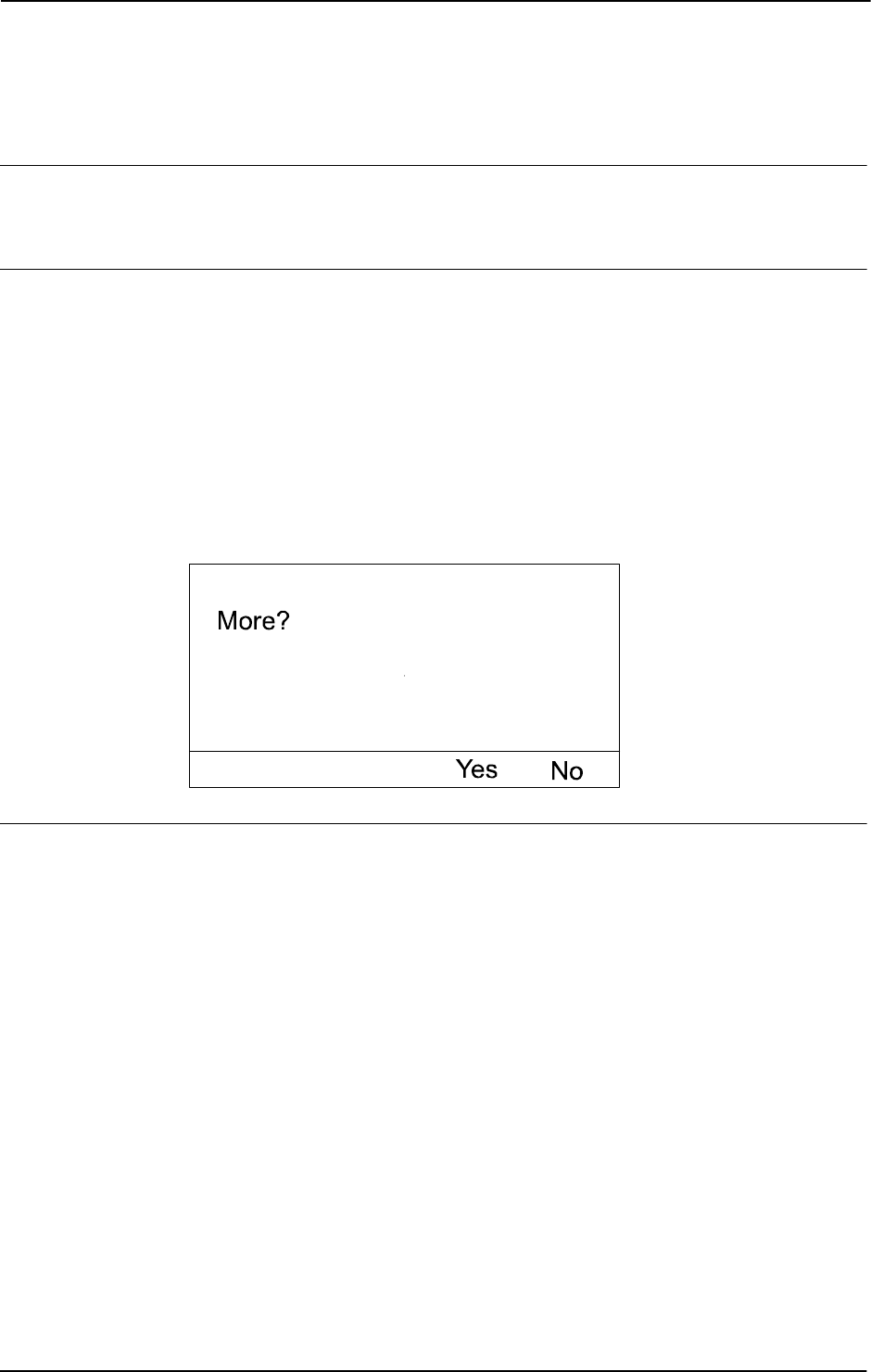
1 Instructions
1.202. TPReadFK - Reads function keys
RobotWare - OS
3HAC 16581-1 Revision: J560
© Copyright 2004-2010 ABB. All rights reserved.
1.202. TPReadFK - Reads function keys
Usage
TPReadFK (FlexPendant Read Function Key) is used to write text on the functions keys and
to find out which key is depressed.
Basic examples
Basic examples of the instruction
TPReadFK are illustrated below.
See also More examples on page 562.
Example 1
TPReadFK reg1, "More?", stEmpty, stEmpty, stEmpty, "Yes", "No";
The text More? is written on the FlexPendant display and the function keys 4 and 5 are
activated by means of the text strings
Yes and No respectively (see figure below ). Program
execution waits until one of the function keys 4 or 5 is pressed. In other words,
reg1 will be
assigned 4 or 5 depending on which of the keys are pressed.
The figure shows that the operator can put in information via the function keys.
xx0500002345
Arguments
TPReadFK TPAnswer TPText TPFK1 TPFK2 TPFK3 TPFK4 TPFK5 [\MaxTime]
[\DIBreak] [\DOBreak] [\BreakFlag]
TPAnswer
Data type: num
The variable for which, depending on which key is pressed, the numeric value 1..5 is returned.
If the function key 1 is pressed then 1 is returned, and so on.
TPText
Data type: string
The information text to be written on the display (a maximum of 80 characters, with 40
characters/row).
Continues on next page

1 Instructions
1.202. TPReadFK - Reads function keys
RobotWare - OS
5613HAC 16581-1 Revision: J
© Copyright 2004-2010 ABB. All rights reserved.
TPFKx
Function key text
Data type:
string
The text to be written on the appropriate function key (a maximum of 45 characters). TPFK1
is the left-most key.
Function keys without text are specified by the predefined string constant
stEmpty with
value empty string (“”).
[\MaxTime]
Data type: num
The maximum amount of time in seconds that program execution waits. If no function key is
pressed within this time then the program continues to execute in the error handler unless the
BreakFlag is used (see below). The constant
ERR_TP_MAXTIME can be used to test whether
or not the maximum time has elapsed.
[\DIBreak]
Digital Input Break
Data type:
signaldi
The digital signal that may interrupt the operator dialog. If no function key is pressed when
the signal is set to 1 (or is already 1) then the program continues to execute in the error handler
unless the
BreakFlag is used (see below). The constant ERR_TP_DIBREAK can be used to
test whether or not this has occurred.
[\DOBreak]
Digital Output Break
Data type:
signaldo
The digital signal that supports termination request from other tasks. If no button is selected
when the signal is set to 1 (or is already 1) then the program continues to execute in the error
handler unless the
BreakFlag is used (see below). The constant ERR_TP_DOBREAK can be
used to test whether or not this has occurred.
[\BreakFlag]
Data type: errnum
A variable that will hold the error code if MaxTime, DIBreak, or DOBreak is used. If this
optional variable is omitted then the error handler will be executed. The constants
ERR_TP_MAXTIME, ERR_TP_DIBREAK, and ERR_TP_DOBREAK can be used to select the
reason.
Continued
Continues on next page

1 Instructions
1.202. TPReadFK - Reads function keys
RobotWare - OS
3HAC 16581-1 Revision: J562
© Copyright 2004-2010 ABB. All rights reserved.
Program execution
The information text is always written on a new line. If the display is full of text then this
body of text is moved up one line first. There can be up to 7 lines above the new written text.
Text is written on the appropriate function keys.
Program execution waits until one of the activated function keys are pressed.
Description of concurrent TPReadFK or TPReadNum request on FlexPendant (TP request)
from the same or other program tasks:
• New TP request from other program tasks will not take focus (new put in queue)
• New TP request from TRAP in the same program task will take focus (old put in
queue)
• Program stop take focus (old put in queue)
• New TP request in program stop state takes focus (old put in queue)
More examples
More examples of how to use the instruction
TPReadFK are illustrated below.
Example 1
VAR errnum errvar;
...
TPReadFK reg1, "Go to service position?", stEmpty, stEmpty,
stEmpty, "Yes","No"
\MaxTime:= 600
\DIBreak:= di5\BreakFlag:= errvar;
IF reg1 = 4 OR errvar = ERR_TP_DIBREAK THEN
MoveL service, v500, fine, tool1;
Stop;
ENDIF
IF errvar = ERR_TP_MAXTIME EXIT;
The robot is moved to the service position if the forth function key ("Yes") is pressed or if
the input 5 is activated. If no answer is given within 10 minutes then the execution is
terminated.
Error handling
If there is a timeout (parameter
\MaxTime) before an input from the operator then the system
variable
ERRNO is set to ERR_TP_MAXTIME, and the execution continues in the error handler.
If digital input is set (parameter
\DIBreak) before an input from the operator then the system
variable
ERRNO is set to ERR_TP_DIBREAK, and the execution continues in the error handler.
If a digital output occurred (parameter
\DOBreak) before an input from the operator then the
system variable
ERRNO is set to ERR_TP_DOBREAK and the execution continues in the error
handler.
If there is no client, e.g. a FlexPendant, to take care of the instruction then the system variable
ERRNO is set to ERR_TP_NO_CLIENT, and the execution continues in the error handler.
These situations can then be dealt with by the error handler.
Continued
Continues on next page

1 Instructions
1.202. TPReadFK - Reads function keys
RobotWare - OS
5633HAC 16581-1 Revision: J
© Copyright 2004-2010 ABB. All rights reserved.
Limitations
Avoid using too small of a value for the timeout parameter
\MaxTime when TPReadFK is
frequently executed, for example in a loop. It can result in an unpredictable behavior of the
system performance, like slowing the FlexPendant response.
Predefined data
CONST string stEmpty := "";
The predefined constant stEmpty should be used for Function Keys without text. Using
stEmpty instead of "" saves about 80 bytes for every Function Key without text.
Syntax
TPReadFK
[TPAnswer ’:=’] <var or pers (INOUT) of num>’,’
[TPText ’:=’] <expression (IN) of string>’,’
[TPFK1 ’:=’] <expression (IN) of string>’,’
[TPFK2 ’:=’] <expression (IN) of string>’,’
[TPFK3 ’:=’] <expression (IN) of string>’,’
[TPFK4 ’:=’] <expression (IN) of string>’,’
[TPFK5 ’:=’] <expression (IN) of string>
[’\’MaxTime’:=’ <expression (IN) of num>]
[’\’DIBreak’:=’ <variable (VAR) of signaldi>]
[’\’DOBreak’:=’ <variable (VAR) of signaldo>]
[’\’BreakFlag’:=’ <var or pers (INOUT) of errnum>]’;’
Related information
For information about See
Writing to and reading from the
FlexPendant
Technical reference manual - RAPID overview,
section RAPID summary - Communication
Replying via the FlexPendant Operating manual - IRC5 with FlexPendant,
section Running in production
Clean up the Operator window TPErase - Erases text printed on the
FlexPendant on page 556
Continued

1 Instructions
1.203. TPReadNum - Reads a number from the FlexPendant
RobotWare - OS
3HAC 16581-1 Revision: J564
© Copyright 2004-2010 ABB. All rights reserved.
1.203. TPReadNum - Reads a number from the FlexPendant
Usage
TPReadNum (FlexPendant Read Numerical) is used to read a number from the FlexPendant.
Basic examples
Basic examples of the instruction
TPReadNum are illustrated below.
See also More examples on page 565.
Example 1
TPReadNum reg1, "How many units should be produced?";
The text How many units should be produced? is written on the FlexPendant display.
Program execution waits until a number has been input from the numeric keyboard on the
FlexPendant. That number is stored in
reg1.
Arguments
TPReadNum TPAnswer TPText [\MaxTime] [\DIBreak] [\DOBreak]
[\BreakFlag]
TPAnswer
Data type: num
The variable for which the number input via the FlexPendant is returned.
TPText
Data type: string
The information text to be written on the FlexPendant (a maximum of 80 characters with 40
characters per row).
[\MaxTime]
Data type: num
The maximum amount of time that program execution waits. If no number is input within this
time, the program continues to execute in the error handler unless the
BreakFlag is used (see
below). The constant
ERR_TP_MAXTIME can be used to test whether or not the maximum time
has elapsed.
[\DIBreak]
Digital Input Break
Data type:
signaldi
The digital signal that may interrupt the operator dialog. If no number is input when the signal
is set to 1 (or is already 1), the program continues to execute in the error handler unless the
BreakFlag is used (see below). The constant ERR_TP_DIBREAK can be used to test whether
or not this has occurred.
Continues on next page

1 Instructions
1.203. TPReadNum - Reads a number from the FlexPendant
RobotWare - OS
5653HAC 16581-1 Revision: J
© Copyright 2004-2010 ABB. All rights reserved.
[\DOBreak]
Digital Output Break
Data type:
signaldo
The digital signal that supports termination request from other tasks. If no button is selected
when the signal is set to 1 (or is already 1), the program continues to execute in the error
handler unless the
BreakFlag is used (see below). The constant ERR_TP_DOBREAK can be
used to test whether or not this has occurred.
[\BreakFlag]
Data type: errnum
A variable that will hold the error code if MaxTime, DIBreak or DOBreak is used. If this
optional variable is omitted, the error handler will be executed. The constants
ERR_TP_MAXTIME, ERR_TP_DIBREAK and ERR_TP_DOBREAK can be used to select the
reason.
Program execution
The information text is always written on a new line. If the display is full of text, this body of
text is moved up one line first. There can be up to 7 lines above the new text written.
Program execution waits until a number is typed on the numeric keyboard (followed by Enter
or OK) or the instruction is interrupted by a time out or signal action.
Reference to
TPReadFK about description of concurrent TPReadFK or TPReadNum request
on FlexPendant from same or other program tasks.
More examples
More examples of how to use the instruction
TPReadNum are illustrated below.
Example 1
TPReadNum reg1, "How many units should be produced?";
FOR i FROM 1 TO reg1 DO
produce_part;
ENDFOR
The text How many units should be produced? is written on the FlexPendant display.
The routine
produce_part is then repeated the number of times that is input via the
FlexPendant.
Error handling
If timeout occurs (parameter
\MaxTime) before input from the operator, the system variable
ERRNO is set to ERR_TP_MAXTIME and the execution continues in the error handler.
If the digital input (parameter
\DIBreak) is set before an input from the operator, the system
variable
ERRNO is set to ERR_TP_DIBREAK and the execution continues in the error handler.
If the digital output (parameter
\DOBreak) is set before an input from the operator, the system
variable
ERRNO is set to ERR_TP_DOBREAK and the execution continues in the error handler.
If there is no client, e.g. a FlexPendant, to take care of the instruction, the system variable
ERRNO is set to ERR_TP_NO_CLIENT and the execution continues in the error handler.
These situations can then be dealt with by the error handler.
Continued
Continues on next page

1 Instructions
1.203. TPReadNum - Reads a number from the FlexPendant
RobotWare - OS
3HAC 16581-1 Revision: J566
© Copyright 2004-2010 ABB. All rights reserved.
Syntax
TPReadNum
[TPAnswer’:=’] <var or pers (INOUT) of num>’,’
[TPText’:=’] <expression (IN) of string>
[’\’MaxTime’:=’ <expression (IN) of num>]
[’\’DIBreak’:=’ <variable (VAR) of signaldi>]
[’\’DOBreak’:=’ <variable (VAR) of signaldo>]
[’\’BreakFlag’:=’ <var or pers (INOUT) of errnum>] ’;’
Related information
For information about See
Writing to and reading from the
FlexPendant
Technical reference manual - RAPID overview,
section RAPID summary - Communication
Entering a number on the FlexPendant Operating manual - IRC5 with FlexPendant,
section Running in production
Examples of how to use the arguments
MaxTime, DIBreak and BreakFlag
TPReadFK - Reads function keys on page 560
Clean up the Operator window TPErase - Erases text printed on the
FlexPendant on page 556
Continued

1 Instructions
1.204. TPShow - Switch window on the FlexPendant
RobotWare - OS
5673HAC 16581-1 Revision: J
© Copyright 2004-2010 ABB. All rights reserved.
1.204. TPShow - Switch window on the FlexPendant
Usage
TPShow (FlexPendant Show) is used to select FlexPendant window from RAPID.
Basic examples
Basic examples of the instruction
TPShow are illustrated below.
Example 1
TPShow TP_LATEST;
The latest used FlexPendant Window before the current FlexPendant window will be active
after execution of this instruction.
Arguments
TPShow Window
Window
Data type: tpnum
The window TP_LATEST will show the latest used FlexPendant window before current
FlexPendant window.
Predefined data
CONST tpnum TP_LATEST := 2;
Program execution
The selected FlexPendant window will be activated.
Syntax
TPShow
[Window’:=’] <expression (IN) of tpnum> ´;’
Related information
For information about See
Communicating using the FlexPendant Technical reference manual - RAPID overview,
section RAPID summary - Communication
FlexPendant Window number tpnum - FlexPendant window number on page
1211
Clean up the Operator window TPErase - Erases text printed on the
FlexPendant on page 556

1 Instructions
1.205. TPWrite - Writes on the FlexPendant
RobotWare - OS
3HAC 16581-1 Revision: J568
© Copyright 2004-2010 ABB. All rights reserved.
1.205. TPWrite - Writes on the FlexPendant
Usage
TPWrite (FlexPendant Write) is used to write text on the FlexPendant. The value of certain
data can be written as well as text.
Basic examples
Basic examples of the instruction
TPWrite are illustrated below.
Example 1
TPWrite "Execution started";
The text Execution started is written on the FlexPendant.
Example 2
TPWrite "No of produced parts="\Num:=reg1;
If, for example, reg1 holds the value 5 then the text No of produced parts=5 is written
on the FlexPendant.
Arguments
TPWrite String [\Num] | [\Bool] | [\Pos] | [\Orient] | [\Dnum]
String
Data type: string
The text string to be written (a maximum of 80 characters, with 40 characters/row).
[\Num]
Numeric
Data type:
num
The data whose numeric value is to be written after the text string.
[\Bool]
Boolean
Data type:
bool
The data whose logical value is to be written after the text string.
[\Pos]
Position
Data type:
pos
The data whose position is to be written after the text string.
[\Orient]
Orientation
Data type:
orient
The data whose orientation is to be written after the text string.
[\Dnum]
Numeric
Data type:
dnum
The data whose numeric value is to be written after the text string.
Continues on next page

1 Instructions
1.205. TPWrite - Writes on the FlexPendant
RobotWare - OS
5693HAC 16581-1 Revision: J
© Copyright 2004-2010 ABB. All rights reserved.
Program execution
Text written on the FlexPendant always begins on a new line. When the display is full of text
(11 lines) then this text is moved up one line first.
If one of the arguments
\Num, \Dnum, \Bool, \Pos, or \Orient is used then its value is
first converted to a text string before it is added to the first string. The conversion from value
to text string takes place as follows:
The value is converted to a string with standard RAPID format. This means, in principle, 6
significant digits. If the decimal part is less than 0.000005 or greater than 0.999995 then the
number is rounded to an integer.
Limitations
The arguments
\Num, \Dnum, \Bool, \Pos, and \Orient are mutually exclusive and thus
cannot be used simultaneously in the same instruction.
Syntax
TPWrite
[TPText’:=’] <expression (IN) of string>
[’\’Num’:=’ <expression (IN) of num> ]
| [’\’Bool’:=’ <expression (IN) of bool> ]
| [’\’Pos’:=’ <expression (IN) of pos> ]
| [’\’Orient’:=’ <expression (IN) of orient> ]
| [’\’Dnum’:=’ <expression (IN) of dnum> ]’;’
Related information
Argument Value Text string
\Num 23 "23"
\Num 1.141367 "1.14137"
\Bool TRUE "TRUE"
\Pos [1817.3,905.17,879.11] "[1817.3,905.17,879.11]"
\Orient [0.96593,0,0.25882,0] "[0.96593,0,0.25882,0]"
\Dnum 4294967295 "4294967295"
For information about See
Clearing and reading the FlexPendant Technical reference manual - RAPID overview,
section RAPID summary - Communication
Clean up the Operator window TPErase - Erases text printed on the FlexPendant
on page 556
Continued
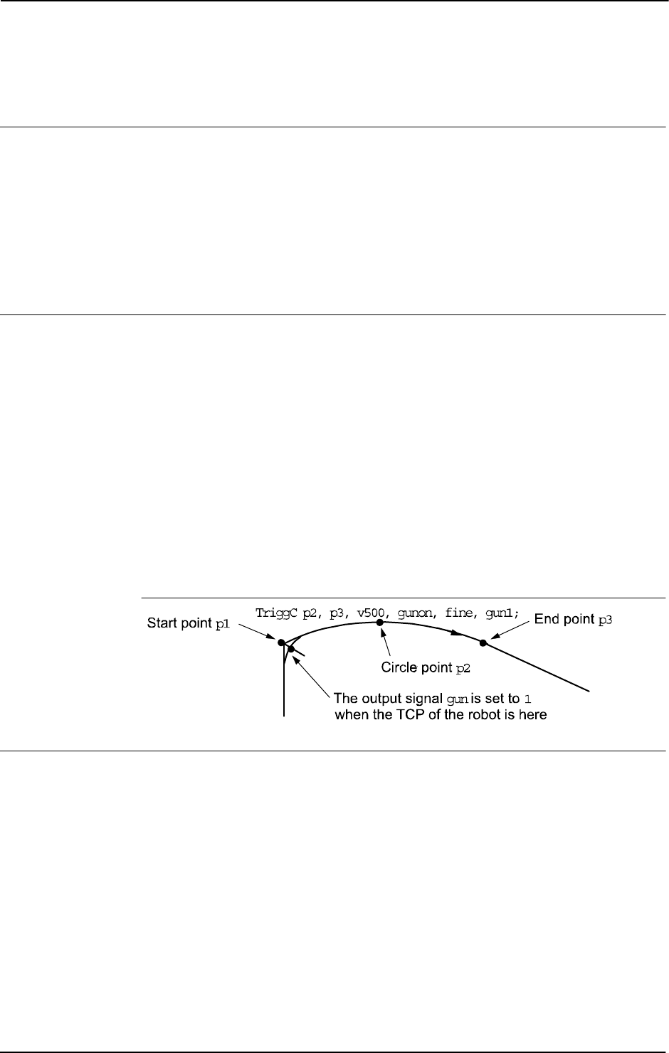
1 Instructions
1.206. TriggC - Circular robot movement with events
RobotWare - OS
3HAC 16581-1 Revision: J570
© Copyright 2004-2010 ABB. All rights reserved.
1.206. TriggC - Circular robot movement with events
Usage
TriggC (Trigg Circular) is used to set output signals and/or run interrupt routines at fixed
positions at the same time that the robot is moving on a circular path.
One or more (max. 8) events can be defined using the instructions
TriggIO, TriggEquip,
TriggInt, TriggCheckIO, TriggSpeed, or TriggRampAO and afterwards these
definitions are referred to in the instruction
TriggC.
This instruction can only be used in the main task
T_ROB1 or, if in a MultiMove system, in
Motion tasks.
Basic examples
Basic examples of the instruction
TriggC are illustrated below.
See also More examples on page 574.
Example 1
VAR triggdata gunon;
TriggIO gunon, 0 \Start \DOp:=gun, 1;
MoveL p1, v500, z50, gun1;
TriggC p2, p3, v500, gunon, fine, gun1;
The digital output signal gun is set when the robot’s TCP passes the midpoint of the corner
path of the point
p1.
The figure shows an example of fixed position I/O event.
xx0500002267
Arguments
TriggC [\Conc] CirPoint ToPoint [\ID] Speed [\T] Trigg_1 [\T2]
[\T3] [\T4] [\T5] [\T6] [\T7] [\T8] Zone [\Inpos] Tool
[\WObj] [ \Corr ]
[ \Conc ]
Concurrent
Data type:
switch
Subsequent instructions are executed while the robot is moving. The argument is usually not
used but can be used to avoid unwanted stops caused by overloaded CPU when using fly-by
points. This is useful when the programmed points are very close together at high speeds. The
argument is also useful when, for example, communicating with external equipment and
Continues on next page

1 Instructions
1.206. TriggC - Circular robot movement with events
RobotWare - OS
5713HAC 16581-1 Revision: J
© Copyright 2004-2010 ABB. All rights reserved.
synchronization between the external equipment and robot movement is not required. It can
also be used to tune the execution of the robot path, to avoid warning 50024 Corner path
failure, or error 40082 Deceleration limit.
When using the argument
\Conc, the number of movement instructions in succession is
limited to 5. In a program section that includes
StorePath-RestoPath, movement
instructions with the argument
\Conc are not permitted.
If this argument is omitted and the
ToPoint is not a stop point then the subsequent instruction
is executed some time before the robot has reached the programmed zone.
This argument can not be used in coordinated synchronized movement in a MultiMove
system.
CirPoint
Data type:
robtarget
The circle point of the robot. See the instruction MoveC for a more detailed description of
circular movement. The circle point is defined as a named position or stored directly in the
instruction (marked with an * in the instruction).
ToPoint
Data type: robtarget
The destination point of the robot and external axes. It is defined as a named position or stored
directly in the instruction (marked with an * in the instruction).
[ \ID ]
Synchronization id
Data type:
identno
This argument must be used in a MultiMove System, if coordinated synchronized movement,
and is not allowed in any other cases.
The specified ID number must be the same in all cooperating program tasks. The ID number
gives a guarantee that the movements are not mixed up at runtime.
Speed
Data type: speeddata
The speed data that applies to movements. Speed data defines the velocity of the tool center
point, the tool reorientation, and the external axes.
[ \T ]
Time
Data type:
num
This argument is used to specify the total time in seconds during which the robot moves. It is
then substituted for the corresponding speed data.
Trigg_1
Data type: triggdata
Variable that refers to trigger conditions and trigger activity defined earlier in the program
using the instructions
TriggIO, TriggEquip, TriggInt, TriggCheckIO, TriggSpeed,
or
TriggRampAO.
Continued
Continues on next page

1 Instructions
1.206. TriggC - Circular robot movement with events
RobotWare - OS
3HAC 16581-1 Revision: J572
© Copyright 2004-2010 ABB. All rights reserved.
[ \T2 ]
Trigg 2
Data type:
triggdata
Variable that refers to trigger conditions and trigger activity defined earlier in the program
using the instructions
TriggIO, TriggEquip, TriggInt, TriggCheckIO, TriggSpeed,
or
TriggRampAO.
[ \T3 ]
Trigg 3
Data type:
triggdata
Variable that refers to trigger conditions and trigger activity defined earlier in the program
using the instructions
TriggIO, TriggEquip, TriggInt, TriggCheckIO, TriggSpeed,
or
TriggRampAO.
[ \T4 ]
Trigg 4
Data type:
triggdata
Variable that refers to trigger conditions and trigger activity defined earlier in the program
using the instructions
TriggIO, TriggEquip, TriggInt, TriggCheckIO, TriggSpeed,
or
TriggRampAO.
[ \T5 ]
Trigg 5
Data type:
triggdata
Variable that refers to trigger conditions and trigger activity defined earlier in the program
using the instructions
TriggIO, TriggEquip, TriggInt, TriggCheck, TriggSpeed, or
TriggRampAO.
[ \T6 ]
Trigg 6
Data type:
triggdata
Variable that refers to trigger conditions and trigger activity defined earlier in the program
using the instructions
TriggIO, TriggEquip, TriggInt, TriggCheckIO ,TriggSpeed,
or
TriggRampAO.
[ \T7 ]
Trigg 7
Data type:
triggdata
Variable that refers to trigger conditions and trigger activity defined earlier in the program
using the instructions
TriggIO, TriggEquip, TriggInt, TriggCheckIO, TriggSpeed,
or
TriggRampAO.
Continued
Continues on next page

1 Instructions
1.206. TriggC - Circular robot movement with events
RobotWare - OS
5733HAC 16581-1 Revision: J
© Copyright 2004-2010 ABB. All rights reserved.
[ \T8 ]
Trigg 8
Data type:
triggdata
Variable that refers to trigger conditions and trigger activity defined earlier in the program
using the instructions
TriggIO, TriggEquip, TriggInt, TriggCheckIO, TriggSpeed,
or
TriggRampAO.
Zone
Data type: zonedata
Zone data for the movement. Zone data describes the size of the generated corner path.
[ \Inpos ]
In position
Data type:
stoppointdata
This argument is used to specify the convergence criteria for the position of the robot’s TCP
in the stop point. The stop point data substitutes the zone specified in the
Zone parameter.
Tool
Data type: tooldata
The tool in use when the robot moves. The tool center point is the point that is moved to the
specified destination position.
[ \WObj ]
Work Object
Data type:
wobjdata
The work object (coordinate system) to which the robot position in the instruction is related.
This argument can be omitted and if so then the position is related to the world coordinate
system. If, on the other hand, a stationary TCP or coordinated external axes are used then this
argument must be specified for a linear movement relative to the work object to be performed.
[ \Corr ]
Correction
Data type:
switch
Correction data written to a corrections entry by the instruction CorrWrite will be added to
the path and destination position if this argument is present.
Program execution
See the instruction
MoveC for information about circular movement.
As the trigger conditions are fulfilled when the robot is positioned closer and closer to the end
point, the defined trigger activities are carried out. The trigger conditions are fulfilled either
at a certain distance before the end point of the instruction, or at a certain distance after the
start point of the instruction, or at a certain point in time (limited to a short time) before the
end point of the instruction.
During stepping the execution forward, the I/O activities are carried out but the interrupt
routines are not run. During stepping the execution backward, no trigger activities at all are
carried out.
Continued
Continues on next page

1 Instructions
1.206. TriggC - Circular robot movement with events
RobotWare - OS
3HAC 16581-1 Revision: J574
© Copyright 2004-2010 ABB. All rights reserved.
More examples
More examples of how to use the instruction
TriggC are illustrated below.
Example 1
VAR intnum intno1;
VAR triggdata trigg1;
...
CONNECT intno1 WITH trap1;
TriggInt trigg1, 0.1 \Time, intno1;
...
TriggC p1, p2, v500, trigg1, fine, gun1;
TriggC p3, p4, v500, trigg1, fine, gun1;
...
IDelete intno1;
The interrupt routine trap1 is run when the work point is at a position 0.1 s before the point
p2 or p4 respectively.
Error handling
If the programmed
ScaleValue argument for the specified analog output signal AOp in some
of the connected
TriggSpeed instructions result in out of limit for the analog signal together
with the programmed
Speed in this instruction, then the system variable ERRNO is set to
ERR_AO_LIM.
If the programmed
DipLag argument in some of the connected TriggSpeed instructions is
too big in relation to the used Event Preset Time in System Parameters then the system
variable ERRNO is set to ERR_DIPLAG_LIM.
The system variable ERRNO can be set to ERR_NORUNUNIT if there is no contact with the
I/O unit when entering instruction and the used triggdata depends on a running I/O unit, i.e.
a signal is used in the triggdata.
These errors can be handled in the error handler.
Limitations
General limitations according to instruction
MoveC.
If the current start point deviates from the usual point so that the total positioning length of
the instruction
TriggC is shorter than usual then it may happen that several or all of the
trigger conditions are fulfilled immediately and at the same position. In such cases, the
sequence in which the trigger activities are carried out will be undefined. The program logic
in the user program may not be based on a normal sequence of trigger activities for an
“incomplete movement”.
WARNING!
The instruction
TriggC should never be started from the beginning with the robot in position
after the circle point. Otherwise, the robot will not take the programmed path (positioning
around the circular path in another direction compared to that which is programmed).
Continued
Continues on next page

1 Instructions
1.206. TriggC - Circular robot movement with events
RobotWare - OS
5753HAC 16581-1 Revision: J
© Copyright 2004-2010 ABB. All rights reserved.
Syntax
TriggC
[ ’\’ Conc ’,’]
[ CirPoint’ :=’ ] < expression (IN) of robtarget > ’,’
[ ToPoint’ :=’ ] < expression (IN) of robtarget > ’,’
[ ’\’ ID ’:=’ < expression (IN) of identno >] ’,’
[ Speed ’:=’ ] < expression (IN) of speeddata >
[ ’\’ T ’:=’ < expression (IN) of num > ] ’,’
[Trigg_1 ’:=’ ] < variable (VAR) of triggdata >
[ ’\’ T2 ’:=’ < variable (VAR) of triggdata > ]
[ ’\’ T3 ’:=’ < variable (VAR) of triggdata > ]
[ ’\’ T4 ’:=’ < variable (VAR) of triggdata > ]
[ ’\’ T5 ’:=’ < variable (VAR) of triggdata > ]
[ ’\’ T6 ’:=’ < variable (VAR) of triggdata > ]
[ ’\’ T7 ’:=’ < variable (VAR) of triggdata > ]
[ ’\’ T8 ’:=’ < variable (VAR) of triggdata > ] ´,’
[Zone ’:=’ ] < expression (IN) of zonedata >
[ ’\’ Inpos’ :=’ < expression (IN) of stoppointdata > ]´,’
[ Tool ’:=’ ] < persistent (PERS) of tooldata >
[ ’\’ WObj’ :=’ < persistent (PERS) of wobjdata > ]
[ ’\’ Corr ]’;’
Related information
For information about See
Linear movement with triggers TriggL - Linear robot movements with events on page
603
Joint movement with triggers TriggJ - Axis-wise robot movements with events on
page 597
Move the robot circularly MoveC - Moves the robot circularly on page 236
Definition of triggers TriggIO - Define a fixed position or time I/O event near
a stop point on page 592
TriggEquip - Define a fixed position and time I/O event
on the path on page 582
TriggInt - Defines a position related interrupt on page
588
TriggCheckIO - Defines IO check at a fixed position on
page 577
TriggRampAO - Define a fixed position ramp AO event
on the path on page 616
TriggSpeed - Defines TCP speed proportional analog
output with fixed position-time scale event on page
622
Writes to a corrections entry CorrWrite - Writes to a correction generator on page
77
Circular movement Technical reference manual - RAPID overview,
section Motion and I/O principles - Positioning during
program execution
Definition of velocity speeddata - Speed data on page 1185
Definition of zone data zonedata - Zone data on page 1232
Continued
Continues on next page

1 Instructions
1.206. TriggC - Circular robot movement with events
RobotWare - OS
3HAC 16581-1 Revision: J576
© Copyright 2004-2010 ABB. All rights reserved.
Definition of stop point data stoppointdata - Stop point data on page 1189
Definition of tools tooldata - Tool data on page 1207
Definition of work objects wobjdata - Work object data on page 1224
Motion in general Technical reference manual - RAPID overview,
section Motion and I/O principles
For information about See
Continued
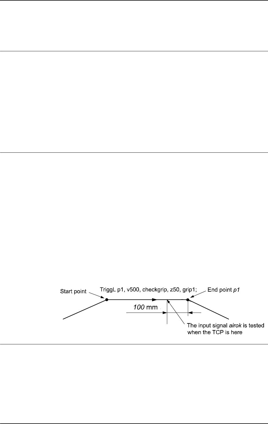
1 Instructions
1.207. TriggCheckIO - Defines IO check at a fixed position
RobotWare - OS
5773HAC 16581-1 Revision: J
© Copyright 2004-2010 ABB. All rights reserved.
1.207. TriggCheckIO - Defines IO check at a fixed position
Usage
TriggCheckIO is used to define conditions for testing the value of a digital, a group of
digital, or an analog input or output signal at a fixed position along the robot’s movement
path. If the condition is fulfilled then there will be no specific action. But if it is not then an
interrupt routine will be run after the robot has optionally stopped on path as fast as possible.
To obtain a fixed position I/O check,
TriggCheckIO compensates for the lag in the control
system (lag between servo and robot).
The data defined is used for implementation in one or more subsequent
TriggL, TriggC, or
TriggJ instructions.
This instruction can only be used in the main task
T_ROB1 or, if in a MultiMove system, in
Motion tasks.
Basic examples
Basic examples of the instruction
TriggCheckIO are illustrated below.
See also More examples on page 580.
Example 1
VAR triggdata checkgrip;
VAR intnum intno1;
CONNECT intno1 WITH trap1;
TriggCheckIO checkgrip, 100, airok, EQ, 1, intno1;
TriggL p1, v500, checkgrip, z50, grip1;
The digital input signal airok is checked to have the value 1 when the TCP is 100 mm
before the point
p1. If it is set then normal execution of the program continues. If it is not set
then the interrupt routine
trap1 is run.
The figure shows an example of fixed position I/O check.
xx0500002254
Arguments
TriggCheckIO TriggData Distance [\Start] | [\Time] Signal Relation
CheckValue |CheckDvalue [\StopMove] Interrupt
TriggData
Data type: triggdata
Variable for storing the triggdata returned from this instruction. These triggdata are
then used in the subsequent
TriggL, TriggC, or TriggJ instructions.
Continues on next page

1 Instructions
1.207. TriggCheckIO - Defines IO check at a fixed position
RobotWare - OS
3HAC 16581-1 Revision: J578
© Copyright 2004-2010 ABB. All rights reserved.
Distance
Data type: num
Defines the position on the path where the I/O check shall occur.
Specified as the distance in mm (positive value) from the end point of the movement path
(applicable if the argument
\Start or \Time is not set).
See the section Program execution for further details.
[ \Start ]
Data type: switch
Used when the distance for the argument Distance starts at the movement start point instead
of the end point.
[ \Time ]
Data type: switch
Used when the value specified for the argument Distance is in fact a time in seconds
(positive value) instead of a distance.
Fixed position I/O in time can only be used for short times (< 0.5 s) before the robot reaches
the end point of the instruction. See the section Limitations for more details.
Signal
Data type: signalxx
The name of the signal that will be tested. May be any type of IO signal.
Relation
Data type: opnum
Defines how to compare the actual value of the signal with the one defined by the argument
CheckValue. Refer to the opnum data type for the list of the predefined constants to be used.
CheckValue
Data type: num
Value to which the actual value of the input or output signal is to be compared (within the
allowed range for the current signal). If the signal is a digital signal, it must be an integer
value.
If the signal is a digital group signal, the permitted value is dependent on the number of
signals in the group. Max value that can be used in the
CheckValue argument is 8388608,
and that is the value a 23 bit digital group signal can have as maximum value (see ranges for
num).
CheckDvalue
Data type: dnum
Value to which the actual value of the input or output signal is to be compared (within the
allowed range for the current signal). If the signal is a digital signal, it must be an integer
value.
If the signal is a digital group signal, the permitted value is dependent on the number of
signals in the group. The maximal amout of signal bits a digital group signal can have is 32.
With a
dnum variable it is possible to cover the value range 0-4294967295, which is the value
range a 32 bits digital signal can have.
Continued
Continues on next page
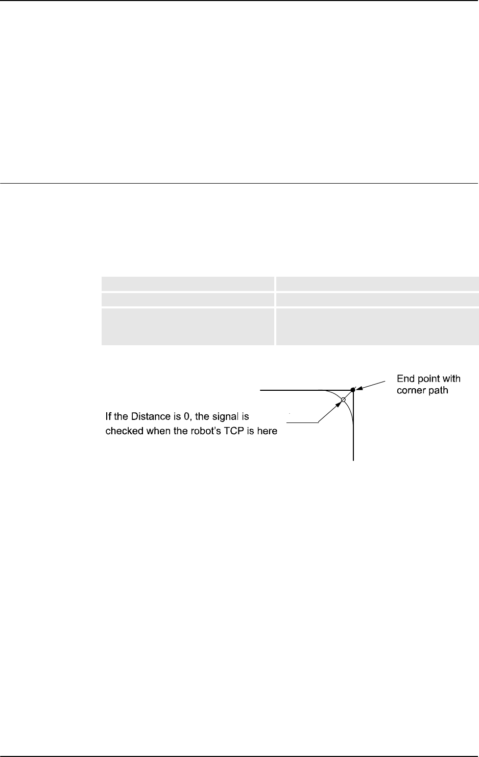
1 Instructions
1.207. TriggCheckIO - Defines IO check at a fixed position
RobotWare - OS
5793HAC 16581-1 Revision: J
© Copyright 2004-2010 ABB. All rights reserved.
[ \StopMove ]
Data type: switch
Specifies that if the condition is not fulfilled then the robot will stop on path as quickly as
possible before the interrupt routine is run.
Interrupt
Data type: intnum
Variable used to identify the interrupt routine to run.
Program execution
When running the instruction
TriggCheckIO, the trigger condition is stored in a specified
variable for the argument
TriggData.
Afterwards, when one of the instructions
TriggL, TriggC, or TriggJ is executed, the
following are applicable with regard to the definitions in
TriggCheckIO:
The table describes distance specified in the argument
Distance:
The figure shows fixed position I/O check on a corner path.
xx0500002256
The fixed position I/O check will be done when the start point (end point) is passed if the
specified distance from the end point (start point) is not within the length of movement of the
current instruction (
TriggL...).
When the TCP of the robot is at specified place on the path, the following I/O check will be
done by the system:
• Read the value of the I/O signal.
• Compare the read value with CheckValue according specified Relation.
• If the comparison is TRUE then nothing more is done.
• If the comparison is FALSE then following is done:
• If optional parameter \StopMove is present then the robot is stopped on the path as
quickly as possible.
• Generate and execute the specified TRAP routine.
Linear movement The straight line distance
Circular movement The circle arc length
Non-linear movement The approximate arc length along the path (to
obtain adequate accuracy, the distance should
not exceed one half of the arc length).
Continued
Continues on next page

1 Instructions
1.207. TriggCheckIO - Defines IO check at a fixed position
RobotWare - OS
3HAC 16581-1 Revision: J580
© Copyright 2004-2010 ABB. All rights reserved.
More examples
More examples of how to use the instruction
TriggCheckIO are illustrated below.
Example 1
VAR triggdata checkgate;
VAR intnum gateclosed;
CONNECT gateclosed WITH waitgate;
TriggCheckIO checkgate, 150, gatedi, EQ, 1 \StopMove, gateclosed;
TriggL p1, v600, checkgate, z50, grip1;
...
TRAP waitgate
! log some information
...
WaitDI gatedi,1;
StartMove;
ENDTRAP
The gate for the next workpiece operation is checked to be open (digital input signal gatedi
is checked to have the value 1) when the TCP is 150 mm before the point p1. If it is open
then the robot will move on to
p1 and continue. If it is not open then the robot is stopped on
path and the interrupt routine
waitgate is run. This interrupt routine logs some information
and typically waits for the conditions to be OK to execute a
StartMove instruction in order
to restart the interrupted path.
Error handling
The following recoverable error can be generated. The error can be handled in an error
handler. The system variable
ERRNO will be set to:
ERR_GO_LIM
if the programmed CheckValue or CheckDvalue argument for the specified digital group
output signal
Signal is outside limits.
ERR_AO_LIM
if the programmed CheckValue or CheckDvalue argument for the specified analog output
signal
Signal is outside limits.
Limitations
I/O checks with distance (without the argument
\Time) is intended for flying points (corner
path). I/O checks with distance, using stop points, results in worse accuracy than specified
below.
I/O checks with time (with the argument
\Time) is intended for stop points. I/O checks with
time, using flying points, results in worse accuracy than specified below.
I/O checks with time can only be specified from the end point of the movement. This time
cannot exceed the current braking time of the robot, which is max. approx. 0.5 s (typical
values at speed 500 mm/s for IRB2400 150 ms and for IRB6400 250 ms). If the specified time
is greater that the current braking time then the I/O check will be generated anyway but not
until braking is started (later than specified). However, the whole of the movement time for
the current movement can be utilized during small and fast movements.
Continued
Continues on next page

1 Instructions
1.207. TriggCheckIO - Defines IO check at a fixed position
RobotWare - OS
5813HAC 16581-1 Revision: J
© Copyright 2004-2010 ABB. All rights reserved.
Typical absolute accuracy values for testing of digital inputs +/- 5 ms. Typical repeat accuracy
values for testing of digital inputs +/- 2 ms.
Syntax
TriggCheckIO
[ TriggData ’:=’ ] < variable (VAR) of triggdata> ´,’
[ Distance’ :=’ ] < expression (IN) of num>
[ ’\’ Start ] | [ ’\’ Time ] ´,’
[ Signal ’:=’ ] < variable (VAR) of anytype> ´,’
[ Relation’ :=’ ] < expression (IN) of opnum> ´,’
[ CheckValue’ :=’ ] < expression (IN) of num>
| [ CheckDvalue’ :=’ ] < expression (IN) of dnum>
[ ’\’ StopMove] ´,’
[ Interrupt’ :=’ ] < variable(VAR) of intnum> ´;’
Related information
For information about See
Use of triggers TriggL - Linear robot movements with events on page
603
TriggC - Circular robot movement with events on page
570
TriggJ - Axis-wise robot movements with events on
page 597
Definition of position-time I/O event TriggIO - Define a fixed position or time I/O event near
a stop point on page 592
TriggEquip - Define a fixed position and time I/O event
on the path on page 582
Definition of position related
interrupts
TriggInt - Defines a position related interrupt on page
588
Storage of trigg data triggdata - Positioning events, trigg on page 1213
Definition of comparison operators opnum - Comparison operator on page 1149I
Continued
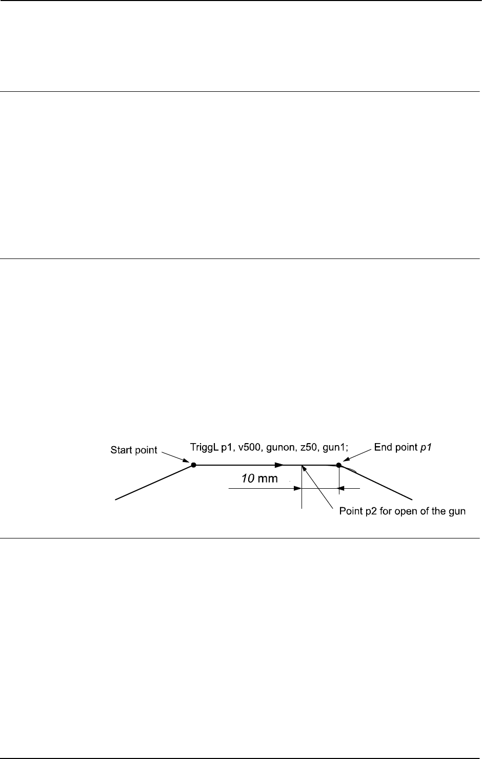
1 Instructions
1.208. TriggEquip - Define a fixed position and time I/O event on the path
RobotWare - OS
3HAC 16581-1 Revision: J582
© Copyright 2004-2010 ABB. All rights reserved.
1.208. TriggEquip - Define a fixed position and time I/O event on the path
Usage
TriggEquip (Trigg Equipment) is used to define conditions and actions for setting a digital,
a group of digital, or an analog output signal at a fixed position along the robot’s movement
path with possibility to do time compensation for the lag in the external equipment.
TriggIO (not TriggEquip) should always be used if there is need for good accuracy of the
I/O settings near a stop point.
The data defined is used for implementation in one or more subsequent
TriggL, TriggC, or
TriggJ instructions.
This instruction can only be used in the main task
T_ROB1 or, if in a MultiMove system, in
Motion tasks.
Basic examples
Basic examples of the instruction
TriggEquip are illustrated below.
See also More examples on page 585.
Example 1
VAR triggdata gunon;
...
TriggEquip gunon, 10, 0.1 \DOp:=gun, 1;
TriggL p1, v500, gunon, z50, gun1;
The tool gun1 starts to open when its TCP is 0,1 s before the fictitious point p2 (10 mm
before point
p1). The gun is full open when TCP reach point p2.
The figure shows an example of a fixed position time I/O event.
xx0500002260
Arguments
TriggEquip TriggData Distance [\Start] EquipLag [\DOp] | [\GOp]|
[\AOp] | [\ProcID] SetValue | SetDvalue [\Inhib]
TriggData
Data type: triggdata
Variable for storing the triggdata returned from this instruction. These triggdata are
then used in the subsequent
TriggL, TriggC, or TriggJ instructions.
Continues on next page
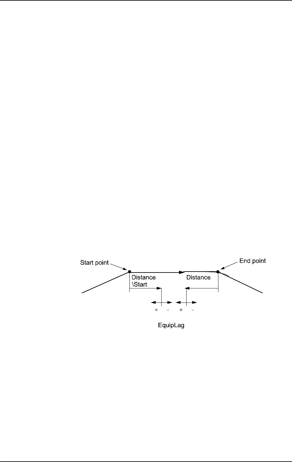
1 Instructions
1.208. TriggEquip - Define a fixed position and time I/O event on the path
RobotWare - OS
5833HAC 16581-1 Revision: J
© Copyright 2004-2010 ABB. All rights reserved.
Distance
Data type: num
Defines the position on the path where the I/O equipment event shall occur.
Specified as the distance in mm (positive value) from the end point of the movement path
(applicable if the argument
\Start is not set).
See the section Program execution for further details.
[ \Start ]
Data type: switch
Used when the distance for the argument Distance starts at the movement start point instead
of the end point.
EquipLag
Equipment Lag
Data type:
num
Specify the lag for the external equipment in s.
For compensation of external equipment lag, use a positive argument value. Positive
argument value means that the I/O signal is set by the robot system at a specified time before
the TCP physically reaches the specified distance in relation to the movement start or end
point.
Negative argument value means that the I/O signal is set by the robot system at a specified
time after that the TCP has physically passed the specified distance in relation to the
movement start or end point.
The figure shows use of argument
EquipLag.
xx0500002262
[ \DOp ]
Digital Output
Data type:
signaldo
The name of the signal when a digital output signal shall be changed.
[ \GOp ]
Group Output
Data type:
signalgo
The name of the signal when a group of digital output signals shall be changed.
Continued
Continues on next page

1 Instructions
1.208. TriggEquip - Define a fixed position and time I/O event on the path
RobotWare - OS
3HAC 16581-1 Revision: J584
© Copyright 2004-2010 ABB. All rights reserved.
[ \AOp ]
Analog Output
Data type:
signalao
The name of the signal when a analog output signal shall be changed.
[ \ProcID ]
Process Identity
Data type:
num
Not implemented for customer use.
(The identity of the IPM process to receive the event. The selector is specified in the argument
SetValue.)
SetValue
Data type: num
The desired value of the signal (within the allowed range for the current signal). If the signal
is a digital signal, it must be an integer value. If the signal is a digital group signal, the
permitted value is dependent on the number of signals in the group. Max value that can be
used in the
SetValue argument is 8388608, and that is the value a 23 bit digital group signal
can have as maximum value (see ranges for
num).
SetDvalue
Data type: dnum
The desired value of the signal (within the allowed range for the current signal). If the signal
is a digital signal, it must be an integer value. If the signal is a digital group signal, the
permitted value is dependent on the number of signals in the group. The maximal amout of
signal bits a digital group signal can have is 32. With a
dnum variable it is possible to cover
the value range 0-4294967295, which is the value range a 32 bits digital signal can have.
[ \Inhib ]
Inhibit
Data type:
bool
The name of a persistent variable flag for inhibiting the setting of the signal at runtime.
If this optional argument is used and the actual value of the specified flag is TRUE at the
position-time for setting of the signal then the specified signal (
DOp, GOp or AOp) will be set
to 0 instead of a specified value.
Program execution
When running the instruction
TriggEquip, the trigger condition is stored in the specified
variable for the argument
TriggData.
Afterwards, when one of the instructions
TriggL, TriggC, or TriggJ is executed then the
following are applicable with regard to the definitions in
TriggEquip:
The table describes the distance specified in the argument
Distance:
Linear movement The straight line distance
Circular movement The circle arc length
Non-linear movement The approximate arc length along the path (to
obtain adequate accuracy, the distance should
not exceed one half of the arc length).
Continued
Continues on next page
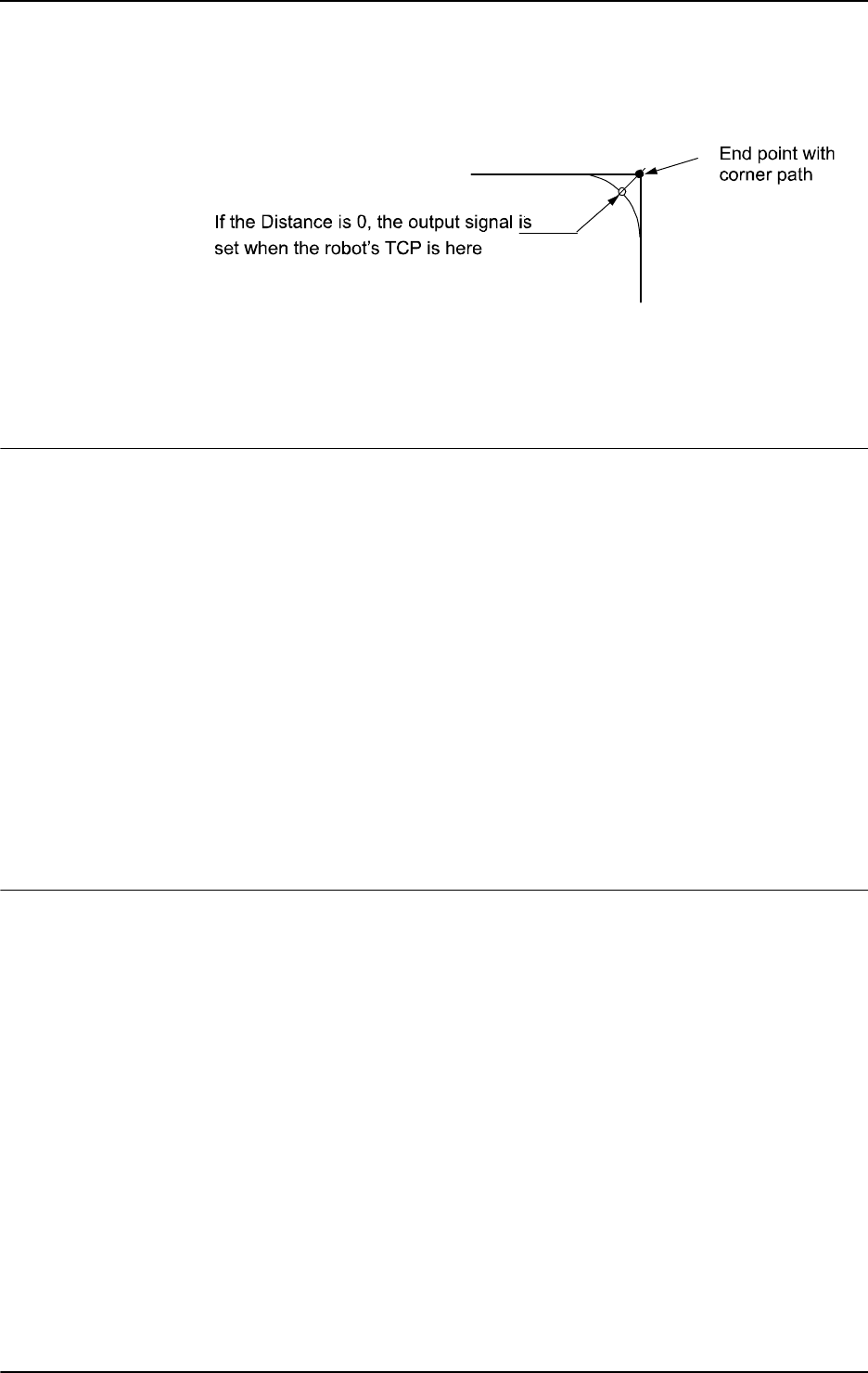
1 Instructions
1.208. TriggEquip - Define a fixed position and time I/O event on the path
RobotWare - OS
5853HAC 16581-1 Revision: J
© Copyright 2004-2010 ABB. All rights reserved.
The figure shows fixed position time I/O on a corner path.
xx0500002263
The position-time related event will be generated when the start point (end point) is passed if
the specified distance from the end point (start point) is not within the length of movement of
the current instruction (
TriggL...). With use of argument EquipLag with negative time
(delay), the I/O signal can be set after the end point.
More examples
More examples of how to use the instruction
TriggEquip are illustrated below.
Example 1
VAR triggdata glueflow;
...
TriggEquip glueflow, 1 \Start, 0.05 \AOp:=glue, 5.3;
MoveJ p1, v1000, z50, tool1;
TriggL p2, v500, glueflow, z50, tool1;
The analog output signal glue is set to the value 5.3 when the TCP passes a point located
1 mm after the start point p1 with compensation for equipment lag 0.05 s.
Example 2
...
TriggL p3, v500, glueflow, z50, tool1;
The analog output signal glue is set once more to the value 5.3 when the TCP passes a
point located
1 mm after the start point p2.
Error handling
If the programmed
SetValue argument for the specified analog output signal AOp is out of
limit then the system variable ERRNO is set to ERR_AO_LIM. This error can be handled in
the error handler.
If the programmed
SetValue or SetDvalue argument for the specified digital group output
signal
GOp is out of limit then the system variable ERRNO is set to ERR_GO_LIM. This error
can be handled in the error handler.
Continued
Continues on next page

1 Instructions
1.208. TriggEquip - Define a fixed position and time I/O event on the path
RobotWare - OS
3HAC 16581-1 Revision: J586
© Copyright 2004-2010 ABB. All rights reserved.
Limitations
I/O events with distance is intended for flying points (corner path). I/O events with distance,
using stop points, results in worse accuracy than specified below.
Regarding the accuracy for I/O events with distance and using flying points, the following is
applicable when setting a digital output at a specified distance from the start point or end point
in the instruction
TriggL or TriggC:
• Accuracy specified below is valid for positive EquipLag parameter < 40 ms,
equivalent to the lag in the robot servo (without changing the system parameter
Event
Preset Time
). The lag can vary between different robot types. For example it is
lower for IRB140.
• Accuracy specified below is valid for positive EquipLag parameter < configured
Event Preset Time
(system parameter).
• Accuracy specified below is not valid for positive EquipLag parameter >
configured Event Preset Time (system parameter). In this case, an approximate
method is used in which the dynamic limitations of the robot are not taken into
consideration.
SingArea \Wrist must be used in order to achieve an acceptable
accuracy.
• Accuracy specified below is valid for negative EquipLag.
Typical absolute accuracy values for set of digital outputs +/- 5 ms.
Typical repeat accuracy values for set of digital outputs +/- 2 ms.
Syntax
TriggEquip
[ TriggData ’:=’ ] < variable (VAR) of triggdata> ´,’
[ Distance’ :=’ ] < expression (IN) of num>
[ ’\’ Start ] ´,’
[ EquipLag’ :=’ ] < expression (IN) of num>
[ ’\’ DOp’ :=’ < variable (VAR) of signaldo> ]
| [ ’\’ GOp’ :=’ < variable (VAR) of signalgo> ]
| [ ’\’ AOp’ :=’ < variable (VAR) of signalao> ]
| [ ’\’ ProcID’ :=’ < expression (IN) of num> ] ´,’
[ SetValue’ :=’ ] < expression (IN) of num>
| [ SetDvalue’ :=’ ] < expression (IN) of dnum>
[ ’\’ Inhib’ :=’ < persistent (PERS) of bool> ] ´,’
Related information
For information about See
Use of triggers TriggL - Linear robot movements with events on
page 603
TriggC - Circular robot movement with events on
page 570
TriggJ - Axis-wise robot movements with events on
page 597
Continued
Continues on next page

1 Instructions
1.208. TriggEquip - Define a fixed position and time I/O event on the path
RobotWare - OS
5873HAC 16581-1 Revision: J
© Copyright 2004-2010 ABB. All rights reserved.
Definition of other triggs TriggIO - Define a fixed position or time I/O event
near a stop point on page 592
TriggInt - Defines a position related interrupt on
page 588
Define I/O check at a fixed position TriggCheckIO - Defines IO check at a fixed position
on page 577
Storage of trigg data triggdata - Positioning events, trigg on page 1213
Set of I/O SetDO - Changes the value of a digital output
signal on page 440
SetGO - Changes the value of a group of digital
output signals on page 442
SetAO - Changes the value of an analog output
signal on page 431
Configuration of Event preset time Technical reference manual - System parameters,
section Motion
For information about See
Continued
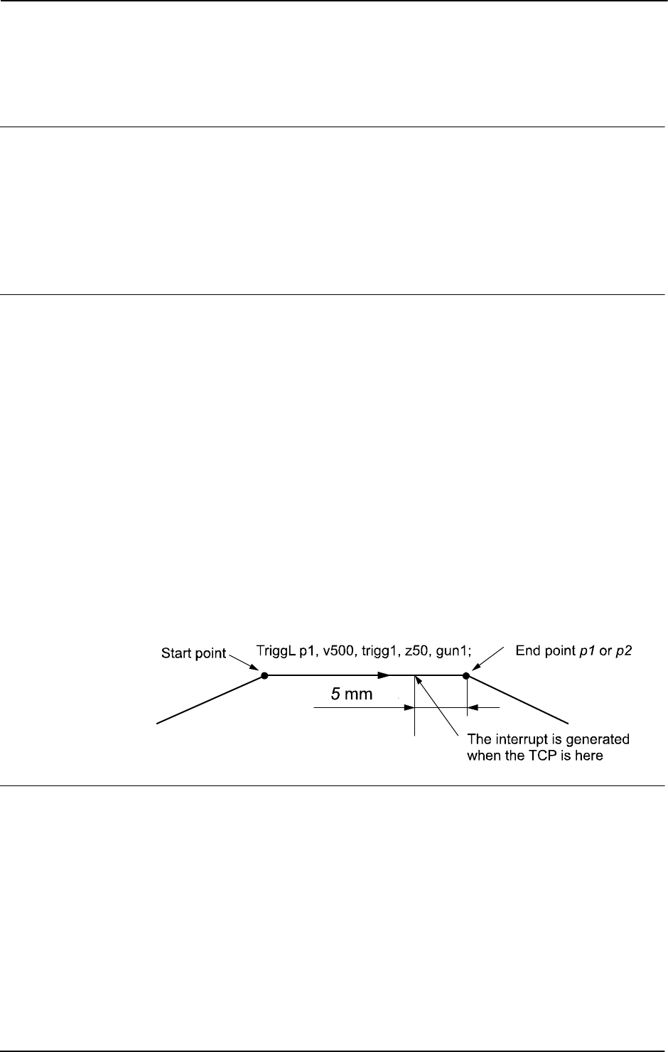
1 Instructions
1.209. TriggInt - Defines a position related interrupt
RobotWare - OS
3HAC 16581-1 Revision: J588
© Copyright 2004-2010 ABB. All rights reserved.
1.209. TriggInt - Defines a position related interrupt
Usage
TriggInt is used to define conditions and actions for running an interrupt routine at a
specified position on the robot’s movement path.
The data defined is used for implementation in one or more subsequent
TriggL, TriggC, or
TriggJ instructions.
This instruction can only be used in the main task
T_ROB1 or, if in a MultiMove System, in
Motion tasks.
Basic examples
Basic examples of the instruction
TriggInt are illustrated below.
Example 1
VAR intnum intno1;
VAR triggdata trigg1;
...
CONNECT intno1 WITH trap1;
TriggInt trigg1, 5, intno1;
...
TriggL p1, v500, trigg1, z50, gun1;
TriggL p2, v500, trigg1, z50, gun1;
...
IDelete intno1;
The interrupt routine trap1 is run when the TCP is at a position 5 mm before the point p1
or p2 respectively.
The figure shows an example of position related interrupt.
xx0500002251
Arguments
TriggInt TriggData Distance [\Start] | [\Time] Interrupt
TriggData
Data type: triggdata
Variable for storing the triggdata returned from this instruction. These triggdata are
then used in the subsequent
TriggL, TriggC, or TriggJ instructions.
Continues on next page
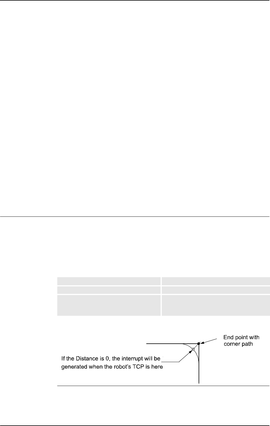
1 Instructions
1.209. TriggInt - Defines a position related interrupt
RobotWare - OS
5893HAC 16581-1 Revision: J
© Copyright 2004-2010 ABB. All rights reserved.
Distance
Data type: num
Defines the position on the path where the interrupt shall be generated.
Specified as the distance in mm (positive value) from the end point of the movement path
(applicable if the argument
\Start or \Time is not set).
See the section entitled Program execution for further details.
[ \Start ]
Data type: switch
Used when the distance for the argument Distance starts at the movement’s start point
instead of the end point.
[ \Time ]
Data type: switch
Used when the value specified for the argument Distance is in fact a time in seconds
(positive value) instead of a distance.
Position related interrupts in time can only be used for short times (< 0.5 s) before the robot
reaches the end point of the instruction. See the section Limitations for more details.
Interrupt
Data type: intnum
Variable used to identify an interrupt.
Program execution
When running the instruction
TriggInt, data is stored in a specified variable for the
argument
TriggData and the interrupt that is specified in the variable for the argument
Interrupt is activated.
Afterwards, when one of the instructions
TriggL, TriggC, or TriggJ is executed, the
following are applicable with regard to the definitions in
TriggInt:
The table describes the distance specified in the argument
Distance:
The figure shows position related interrupt on a corner path.
xx0500002253
Linear movement The straight line distance
Circular movement The circle arc length
Non-linear movement The approximate arc length along the path (to
obtain adequate accuracy, the distance should
not exceed one half of the arc length).
Continued
Continues on next page

1 Instructions
1.209. TriggInt - Defines a position related interrupt
RobotWare - OS
3HAC 16581-1 Revision: J590
© Copyright 2004-2010 ABB. All rights reserved.
The position related interrupt will be generated when the start point (end point) is passed if
the specified distance from the end point (start point) is not within the length of movement of
the current instruction (
TriggL...).
The interrupt is considered to be a safe interrupt. A safe interrupt can not be put in sleep with
instruction
ISleep. The safe interrupt event will be queued at program stop and stepwise
execution, and when starting in continious mode again, the interrupt will be executed. The
only time a safe interrupt will be thrown is when the interrupt queue is full. Then an error will
be reported. The interrupt will not survive program reset, e.g. PP to main.
More examples
More examples of how to use the instruction
TriggInt are illustrated below.
Example 1
This example describes programming of the instructions that interact to generate position
related interrupts:
VAR intnum intno2;
VAR triggdata trigg2;
• Declaration of the variables intno2 and trigg2 (shall not be initiated).
CONNECT intno2 WITH trap2;
• Allocation of interrupt numbers that are stored in the variable intno2.
• The interrupt number is coupled to the interrupt routine trap2.
TriggInt trigg2, 0, intno2;
• The interrupt number in the variable intno2 is flagged as used.
• The interrupt is activated.
• Defined trigger conditions and interrupt numbers are stored in the variable trigg2
TriggL p1, v500, trigg2, z50, gun1;
• The robot is moved to the point p1.
• When the TCP reaches the point p1 an interrupt is generated, and the interrupt routine
trap2 is run.
TriggL p2, v500, trigg2, z50, gun1;
• The robot is moved to the point p2.
• When the TCP reaches the point p2, an interrupt is generated and the interrupt routine
trap2 is run once more.
IDelete intno2;
• The interrupt number in the variable intno2 is de-allocated.
Limitations
Interrupt events with distance (without the argument
\Time) are intended for flying points
(corner path). Interrupt events with distance, using stop points results in worse accuracy than
specified below.
Interrupt events with time (with the argument
\Time) are intended for stop points. Interrupt
events with time, using flying points, result in worse accuracy than specified below. I/O
events with time can only be specified from the end point of the movement. This time cannot
exceed the current braking time of the robot, which is max. approx. 0.5 s (typical values at
speed 500 mm/s for IRB2400 150 ms and for IRB6400 250 ms). If the specified time is
Continued
Continues on next page

1 Instructions
1.209. TriggInt - Defines a position related interrupt
RobotWare - OS
5913HAC 16581-1 Revision: J
© Copyright 2004-2010 ABB. All rights reserved.
greater that the current braking time then the event will be generated anyhow but not until
braking is started (later than specified). However, the whole of the movement time for the
current movement can be utilized during small and fast movements.
Typical absolute accuracy values for generation of interrupts +/- 5 ms. Typical repeat
accuracy values for generation of interrupts +/- 2 ms. Normally there is a delay of 2 to 30 ms
between interrupt generation and response depending on the type of movement being
performed at the time of the interrupt. (Ref. to RAPID reference manual - RAPID overview,
section Basic characteristics - Interrupts).
To obtain the best accuracy when setting an output at a fixed position along the robot’s path,
use the instructions
TriggIO or TriggEquip in preference to the instructions TriggInt
with
SetDO/SetGO/SetAO in an interrupt routine.
Syntax
TriggInt
[ TriggData ’:=’ ] < variable (VAR) of triggdata> ´,’
[ Distance’ :=’ ] < expression (IN) of num>
[ ’\’ Start ] | [ ’\’ Time ] ’,’
[ Interrupt’ :=’ ] < variable (VAR) ofintnum> ’;’
Related information
For information about See
Use of triggers TriggL - Linear robot movements with events on page
603
TriggC - Circular robot movement with events on
page 570
TriggJ - Axis-wise robot movements with events on
page 597
Definition of position fix I/O TriggIO - Define a fixed position or time I/O event
near a stop point on page 592
TriggEquip - Define a fixed position and time I/O
event on the path on page 582
Define I/O check at a fixed position TriggCheckIO - Defines IO check at a fixed position
on page 577
Storage of trigg data triggdata - Positioning events, trigg on page 1213
Interrupts Technical reference manual - RAPID overview,
section Basic characteristics - Interrupts
Continued
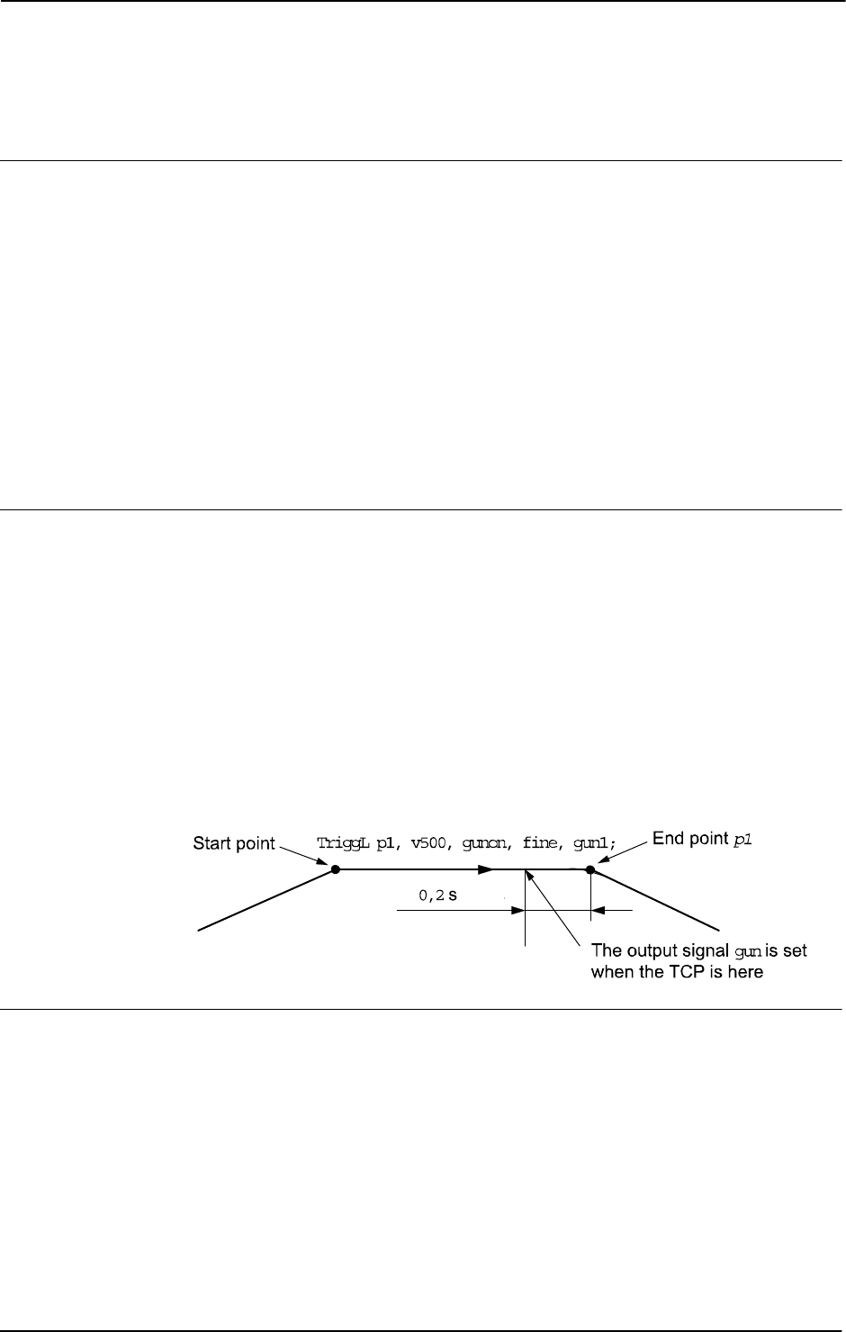
1 Instructions
1.210. TriggIO - Define a fixed position or time I/O event near a stop point
RobotWare - OS
3HAC 16581-1 Revision: J592
© Copyright 2004-2010 ABB. All rights reserved.
1.210. TriggIO - Define a fixed position or time I/O event near a stop point
Usage
TriggIO is used to define conditions and actions for setting a digital, a group of digital, or
an analog output signal at a fixed position along the robot’s movement path.
TriggIO (not TriggEquip) should always be used if needed for good accuracy of the I/O
settings near a stop point.
To obtain a fixed position I/O event,
TriggIO compensates for the lag in the control system
(lag between robot and servo) but not for any lag in the external equipment. For compensation
of both lags use
TriggEquip.
The data defined is used for implementation in one or more subsequent
TriggL, TriggC, or
TriggJ instructions.
This instruction can only be used in the main
T_ROB1 task or, if in a MultiMove system, in
Motion tasks.
Basic examples
Basic example of the instruction
TriggIO are illustrated below.
See also More examples on page 595.
Example 1
VAR triggdata gunon;
...
TriggIO gunon, 0.2\Time\DOp:=gun, 1;
TriggL p1, v500, gunon, fine, gun1;
The digital output signal gun is set to the value 1 when the TCP is 0,2 seconds before the
point
p1.
The figure shows an example of fixed position I/O event.
xx0500002247
Arguments
TriggIO TriggData Distance [\Start] | [\Time] [\DOp] | [\GOp]|
[\AOp] | [\ProcID] SetValue | SetDvalue [\DODelay]
TriggData
Data type: triggdata
Variable for storing the triggdata returned from this instruction. These triggdata are
then used in the subsequent
TriggL, TriggC, or TriggJ instructions.
Continues on next page

1 Instructions
1.210. TriggIO - Define a fixed position or time I/O event near a stop point
RobotWare - OS
5933HAC 16581-1 Revision: J
© Copyright 2004-2010 ABB. All rights reserved.
Distance
Data type: num
Defines the position on the path where the I/O event shall occur.
Specified as the distance in mm (positive value) from the end point of the movement path
(applicable if the argument
\Start or \Time is not set).
See the sections Program execution on page 594, and Limitations on page 595 for further
details.
[ \Start ]
Data type: switch
Used when the distance for the argument Distance starts at the movement start point instead
of the end point.
[ \Time ]
Data type: switch
Used when the value specified for the argument Distance is in fact a time in seconds
(positive value) instead of a distance.
Fixed position I/O in time can only be used for short times (< 0.5 s) before the robot reaches
the end point of the instruction. See the section Limitations for more details.
[ \DOp ]
Digital Output
Data type:
signaldo
The name of the signal when a digital output signal shall be changed.
[ \GOp ]
Group Output
Data type:
signalgo
The name of the signal when a group of digital output signals shall be changed.
[ \AOp ]
Analog Output
Data type:
signalao
The name of the signal when a analog output signal shall be changed.
[ \ProcID ]
Process Identity
Data type:
num
Not implemented for customer use.
(The identity of the IPM process to receive the event. The selector is specified in the argument
SetValue.)
Continued
Continues on next page

1 Instructions
1.210. TriggIO - Define a fixed position or time I/O event near a stop point
RobotWare - OS
3HAC 16581-1 Revision: J594
© Copyright 2004-2010 ABB. All rights reserved.
SetValue
Data type: num
The desired value of the signal (within the allowed range for the current signal). If the signal
is a digital signal, it must be an integer value. If the signal is a digital group signal, the
permitted value is dependent on the number of signals in the group. Max value that can be
used in the
SetValue argument is 8388608, and that is the value a 23 bit digital group signal
can have as maximum value (see ranges for
num).
SetDvalue
Data type: dnum
The desired value of the signal (within the allowed range for the current signal). If the signal
is a digital signal, it must be an integer value. If the signal is a digital group signal, the
permitted value is dependent on the number of signals in the group. The maximal amout of
signal bits a digital group signal can have is 32. With a
dnum variable it is possible to cover
the value range 0-4294967295, which is the value range a 32 bits digital signal can have.
[ \DODelay ]
Digital Output Delay
Data type:
num
Time delay in seconds (positive value) for a digital, group, or analog output signal.
Only used to delay setting of output signals after the robot has reached the specified position.
There will be no delay if the argument is omitted.
The delay is not synchronized with the movement.
Program execution
When running the instruction
TriggIO, the trigger condition is stored in a specified variable
in the argument
TriggData.
Afterwards, when one of the instructions
TriggL, TriggC, or TriggJ is executed, the
following are applicable with regard to the definitions in
TriggIO:
The following table describes the distance specified in the argument
Distance:
The figure shows fixed position I/O on a corner path.
xx0500002248
The fixed position I/O will be generated when the start point (end point) is passed if the
specified distance from the end point (start point) is not within the length of movement of the
current instruction (
Trigg...).
Linear movement The straight line distance
Circular movement The circle arc length
Non-linear movement The approximate arc length along the path (to
obtain adequate accuracy, the distance should
not exceed one half of the arc length).
Continued
Continues on next page

1 Instructions
1.210. TriggIO - Define a fixed position or time I/O event near a stop point
RobotWare - OS
5953HAC 16581-1 Revision: J
© Copyright 2004-2010 ABB. All rights reserved.
More examples
More examples of how to use the instruction
TriggIO are illustrated below.
Example 1
VAR triggdata glueflow;
TriggIO glueflow, 1 \Start \AOp:=glue, 5.3;
MoveJ p1, v1000, z50, tool1;
TriggL p2, v500, glueflow, z50, tool1;
The analog output signal glue is set to the value 5.3 when the work point (TCP) passes a
point located
1 mm after the start point p1.
Example 2
...
TriggL p3, v500, glueflow, z50, tool1;
The analog output signal glue is set once more to the value 5.3 when the work point (TCP)
passes a point located
1 mm after the start point p2.
Error handling
If the programmed
SetValue argument for the specified analog output signal AOp is out of
limit then the system variable ERRNO is set to ERR_AO_LIM. This error can be handled in
the error handler.
If the programmed
SetValue or SetDvalue argument for the specified digital group output
signal
GOp is out of limit then the system variable ERRNO is set to ERR_GO_LIM. This error
can be handled in the error handler.
Limitations
I/O events with distance (without the argument \
Time) is intended for flying points (corner
path). I/O events with distance=0, using stop points, will delay the trigg until the robot has
reached the point with accuracy +/-24 ms.
I/O events with time (with the argument \
Time) are intended for stop points. I/O events with
time, using flying points result in worse accuracy than specified below. I/O events with time
can only be specified from the end point of the movement. This time cannot exceed the
current braking time of the robot, which is max. approx. 0.5 s (typical values at speed 500
mm/s for IRB2400 150 ms and for IRB6400 250 ms). If the specified time is greater than the
current braking time then the event will be generated anyway but not until braking is started
(later than specified). However, the whole of the movement time for the current movement
can be utilized during small and fast movements.
Typical absolute accuracy values for set of digital outputs +/- 5 ms. Typical repeat accuracy
values for set of digital outputs +/- 2 ms.
Continued
Continues on next page

1 Instructions
1.210. TriggIO - Define a fixed position or time I/O event near a stop point
RobotWare - OS
3HAC 16581-1 Revision: J596
© Copyright 2004-2010 ABB. All rights reserved.
Syntax
TriggIO
[ TriggData ’:=’ ] < variable (VAR) of triggdata> ´,’
[ Distance’ :=’ ] < expression (IN) of num>
[ ’\’ Start ] | [ ’\’ Time ]
[ ’\’ DOp’ :=’ < variable (VAR) of signaldo> ]
| [ ’\’ GOp’ :=’ < variable (VAR) of signalgo> ]
| [ ’\’ AOp’ :=’ < variable (VAR) of signalao> ]
| [ ’\’ ProcID’ :=’ < expression (IN) of num> ] ´,’
[ SetValue’ :=’ ] < expression (IN) of num>
| [ SetDvalue’ :=’ ] < expression (IN) of dnum>
[ ’\’ DODelay’ :=’ < expression (IN) of num> ] ´;’
Related information
For information about See
Use of triggers TriggL - Linear robot movements with events on
page 603
TriggC - Circular robot movement with events on
page 570
TriggJ - Axis-wise robot movements with events
on page 597
Definition of position-time I/O event TriggEquip - Define a fixed position and time I/O
event on the path on page 582
Definition of position related interrupts TriggInt - Defines a position related interrupt on
page 588
Storage of trigg data triggdata - Positioning events, trigg on page 1213
Define I/O check at a fixed position TriggCheckIO - Defines IO check at a fixed
position on page 577
Set of I/O SetDO - Changes the value of a digital output
signal on page 440
SetGO - Changes the value of a group of digital
output signals on page 442
SetAO - Changes the value of an analog output
signal on page 431
Continued
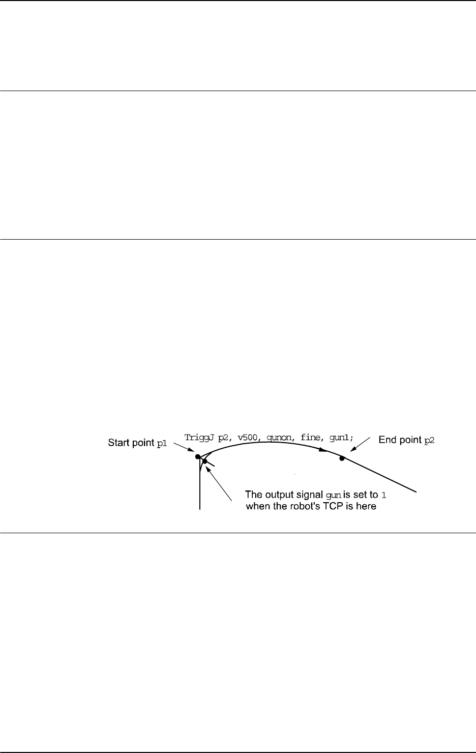
1 Instructions
1.211. TriggJ - Axis-wise robot movements with events
RobotWare - OS
5973HAC 16581-1 Revision: J
© Copyright 2004-2010 ABB. All rights reserved.
1.211. TriggJ - Axis-wise robot movements with events
Usage
TriggJ (TriggJoint) is used to set output signals and/or run interrupt routines at roughly fixed
positions at the same time that the robot is moving quickly from one point to another when
that movement does not have be in a straight line.
One or more (max. 8) events can be defined using the instructions
TriggIO, TriggEquip,
TriggInt, TriggCheckIO , TriggSpeed, or TriggRampAO and afterwards these
definitions are referred to in the instruction
TriggJ.
This instruction can only be used in the main task
T_ROB1 or, if in a MultiMove system, in
Motion tasks.
Basic examples
Basic examples of the instruction
TriggJ are illustrated below.
See also More examples on page 600.
Example 1
VAR triggdata gunon;
...
TriggIO gunon, 0 \Start \DOp:=gun, 1;
MoveL p1, v500, z50, gun1;
TriggJ p2, v500, gunon, fine, gun1;
The digital output signal gun is set when the robot’s TCP passes the midpoint of the corner
path of the point
p1.
The figure shows an example of fixed position I/O event.
xx0500002272
Arguments
TriggJ [\Conc] ToPoint [\ID] Speed [\T] Trigg_1 [ \T2 ] [ \T3 ]
[\T4] [\T5] [\T6] [\T7] [\T8] Zone [\Inpos] Tool [\WObj]
[ \Conc ]
Concurrent
Data type:
switch
Subsequent instructions are executed while the robot is moving. The argument can be used to
avoid unwanted stops caused by overloaded CPU when using fly-by points. This is useful
when the programmed points are very close together at high speeds.
The argument is also useful when, for example, communicating with external equipment and
synchronization between the external equipment and robot movement is not required. It can
also be used to tune the execution of the robot path to avoid warning 50024 Corner path
failure or error 40082 Deceleration limit.
Continues on next page

1 Instructions
1.211. TriggJ - Axis-wise robot movements with events
RobotWare - OS
3HAC 16581-1 Revision: J598
© Copyright 2004-2010 ABB. All rights reserved.
Using the argument \Conc, the number of movement instructions in succession is limited to
5. In a program section that includes
StorePath-RestoPath, movement instructions with
the argument
\Conc are not permitted.
If this argument is omitted then the subsequent instruction is executed after the robot has
reached the specified stop point or 100 ms before the specified zone.
This argument can not be used in coordinated synchronized movement in a MultiMove
System.
ToPoint
Data type: robtarget
The destination point of the robot and external axes. It is defined as a named position or stored
directly in the instruction (marked with an * in the instruction).
[ \ID ]
Synchronization id
Data type:
identno
This argument must be used in a MultiMove System, if it is a coordinated synchronized
movement, and is not allowed in any other cases.
The specified ID number must be the same in all cooperating program tasks. The ID number
gives a guarantee that the movements are not mixed up at runtime.
Speed
Data type: speeddata
The speed data that applies to movements. Speed data defines the velocity of the tool center
point, the tool reorientation, and the external axes.
[ \T ]
Time
Data type:
num
This argument is used to specify the total time in seconds during which the robot moves. It is
then substituted for the corresponding speed data.
Trigg_1
Data type: triggdata
Variable that refers to trigger conditions and trigger activity defined earlier in the program
using the instructions
TriggIO, TriggEquip, TriggInt, TriggCheckIO , TriggSpeed,
or
TriggRampAO.
[ \T2 ]
Trigg 2
Data type:
triggdata
Variable that refers to trigger conditions and trigger activity defined earlier in the program
using the instructions
TriggIO, TriggEquip, TriggInt, TriggCheckIO , TriggSpeed,
or
TriggRampAO.
Continued
Continues on next page

1 Instructions
1.211. TriggJ - Axis-wise robot movements with events
RobotWare - OS
5993HAC 16581-1 Revision: J
© Copyright 2004-2010 ABB. All rights reserved.
[ \T3 ]
Trigg 3
Data type:
triggdata
Variable that refers to trigger conditions and trigger activity defined earlier in the program
using the instructions
TriggIO, TriggEquip, TriggInt, TriggCheckIO , TriggSpeed,
or
TriggRampAO.
[ \T4 ]
Trigg 4
Data type:
triggdata
Variable that refers to trigger conditions and trigger activity defined earlier in the program
using the instructions
TriggIO, TriggEquip, TriggInt, TriggCheckIO , TriggSpeed,
or
TriggRampAO.
[ \T5 ]
Trigg 5
Data type:
triggdata
Variable that refers to trigger conditions and trigger activity defined earlier in the program
using the instructions
TriggIO, TriggEquip, TriggInt, TriggCheckIO, TriggSpeed,
or
TriggRampAO.
[ \T6 ]
Trigg 6
Data type:
triggdata
Variable that refers to trigger conditions and trigger activity defined earlier in the program
using the instructions
TriggIO, TriggEquip, TriggInt, TriggCheckIO, TriggSpeed,
or
TriggRampAO.
[ \T7 ]
Trigg 7
Data type:
triggdata
Variable that refers to trigger conditions and trigger activity defined earlier in the program
using the instructions
TriggIO, TriggEquip, TriggInt, TriggCheckIO, TriggSpeed,
or
TriggRampAO.
[ \T8 ]
Trigg 8
Data type:
triggdata
Variable that refers to trigger conditions and trigger activity defined earlier in the program
using the instructions
TriggIO, TriggEquip, TriggInt, TriggCheckIO, TriggSpeed,
or
TriggRampAO.
Zone
Data type: zonedata
Zone data for the movement. Zone data describes the size of the generated corner path.
Continued
Continues on next page

1 Instructions
1.211. TriggJ - Axis-wise robot movements with events
RobotWare - OS
3HAC 16581-1 Revision: J600
© Copyright 2004-2010 ABB. All rights reserved.
[ \Inpos ]
In position
Data type:
stoppointdata
This argument is used to specify the convergence criteria for the position of the robot’s TCP
in the stop point. The stop point data substitutes the zone specified in the
Zone parameter.
Tool
Data type: tooldata
The tool in use when the robot moves. The tool center point is the point that is moved to the
specified destination position.
[ \WObj ]
Work Object
Data type:
wobjdata
The work object (coordinate system) to which the robot position in the instruction is related.
This argument can be omitted and if so then the position is related to the world coordinate
system. If, on the other hand, a stationary TCP or coordinated external axes are used then this
argument must be specified for a joint movement relative to the work object to be performed.
Program execution
See the instruction
MoveJ for information about joint movement.
As the trigger conditions are fulfilled when the robot is positioned closer and closer to the end
point, the defined trigger activities are carried out. The trigger conditions are fulfilled either
at a certain distance before the end point of the instruction, or at a certain distance after the
start point of the instruction, or at a certain point in time (limited to a short time) before the
end point of the instruction.
During the stepping execution forward, the I/O activities are carried out but the interrupt
routines are not run. During stepping the execution backwards, no trigger activities at all are
carried out.
More examples
More examples of how to use the instruction
TriggJ are illustrated below.
Example 1
VAR intnum intno1;
VAR triggdata trigg1;
...
CONNECT intno1 WITH trap1;
TriggInt trigg1, 0.1 \Time, intno1;
...
TriggJ p1, v500, trigg1, fine, gun1;
TriggJ p2, v500, trigg1, fine, gun1;
...
IDelete intno1;
The interrupt routine trap1 is run when the work point is at a position 0.1 s before the stop
point
p1 or p2 respectively.
Continued
Continues on next page

1 Instructions
1.211. TriggJ - Axis-wise robot movements with events
RobotWare - OS
6013HAC 16581-1 Revision: J
© Copyright 2004-2010 ABB. All rights reserved.
Error handling
If the programmed
ScaleValue argument for the specified analog output signal AOp in some
of the connected
TriggSpeed instructions results in out of limit for the analog signal
together with the programmed
Speed in this instruction, then the system variable ERRNO is
set to ERR_AO_LIM.
If the programmed
DipLag argument in some of the connected TriggSpeed instructions is
too big in relation to the Event Preset Time used in System Parameters then the system
variable ERRNO is set to ERR_DIPLAG_LIM.
The system variable ERRNO can be set to ERR_NORUNUNIT if there is no contact with the
I/O unit when entering instruction and the used triggdata depends on a running I/O unit, i.e.
a signal is used in the triggdata.
These errors can be handled in the error handler.
Limitations
If the current start point deviates from the usual so that the total positioning length of the
instruction
TriggJ is shorter than usual (e.g. at the start of TriggJ with the robot position
at the end point), it may happen that several or all of the trigger conditions are fulfilled
immediately and at the same position. In such cases, the sequence in which the trigger
activities are carried will be undefined. The program logic in the user program may not be
based on a normal sequence of trigger activities for an “incomplete movement”.
Syntax
TriggJ
[ ’\’ Conc ’,’]
[ ToPoint’ :=’ ] < expression (IN) of robtarget >
[ ’\’ ID ’:=’ < expression (IN) of identno >]’,’
[ Speed ’:=’ ] < expression (IN) of speeddata >
[ ’\’ T ’:=’ < expression (IN) of num > ]’,’
[Trigg_1 ’:=’ ] < variable (VAR) of triggdata >
[ ’\’ T2 ’:=’ < variable (VAR) of triggdata > ]
[ ’\’ T3 ’:=’ < variable (VAR) of triggdata > ]
[ ’\’ T4 ’:=’ < variable (VAR) of triggdata > ]
[ ’\’ T5 ’:=’ < variable (VAR) of triggdata > ]
[ ’\’ T6 ’:=’ < variable (VAR) of triggdata > ]
[ ’\’ T7 ’:=’ < variable (VAR) of triggdata > ]
[ ’\’ T8 ’:=’ < variable (VAR) of triggdata > ] ´,’
[Zone ’:=’ ] < expression (IN) of zonedata >
[ ’\’ Inpos ’:=’ < expression (IN) of stoppointdata > ]´,’
[ Tool ’:=’ ] < persistent (PERS) of tooldata >
[ ’\’ WObj’ :=’< persistent (PERS) of wobjdata > ] ’;’
Continued
Continues on next page

1 Instructions
1.211. TriggJ - Axis-wise robot movements with events
RobotWare - OS
3HAC 16581-1 Revision: J602
© Copyright 2004-2010 ABB. All rights reserved.
Related information
For information about See
Linear movement with triggers TriggL - Linear robot movements with events on page
603
Circular movement with triggers TriggC - Circular robot movement with events on page
570
Definition of triggers TriggIO - Define a fixed position or time I/O event near
a stop point on page 592
TriggEquip - Define a fixed position and time I/O event
on the path on page 582
TriggRampAO - Define a fixed position ramp AO event
on the path on page 616
TriggInt - Defines a position related interrupt on page
588
TriggCheckIO - Defines IO check at a fixed position on
page 577
Moves the robot by joint movement MoveJ - Moves the robot by joint movement on page
253
Joint movement Technical reference manual - RAPID overview, section
Motion and I/O principles - Positioning during program
execution
Definition of velocity speeddata - Speed data on page 1185
Definition of zone data zonedata - Zone data on page 1232
Definition of stop point data stoppointdata - Stop point data on page 1189
Definition of tools tooldata - Tool data on page 1207
Definition of work object wobjdata - Work object data on page 1224
Motion in general Technical reference manual - RAPID overview, section
Motion and I/O principles
Continued
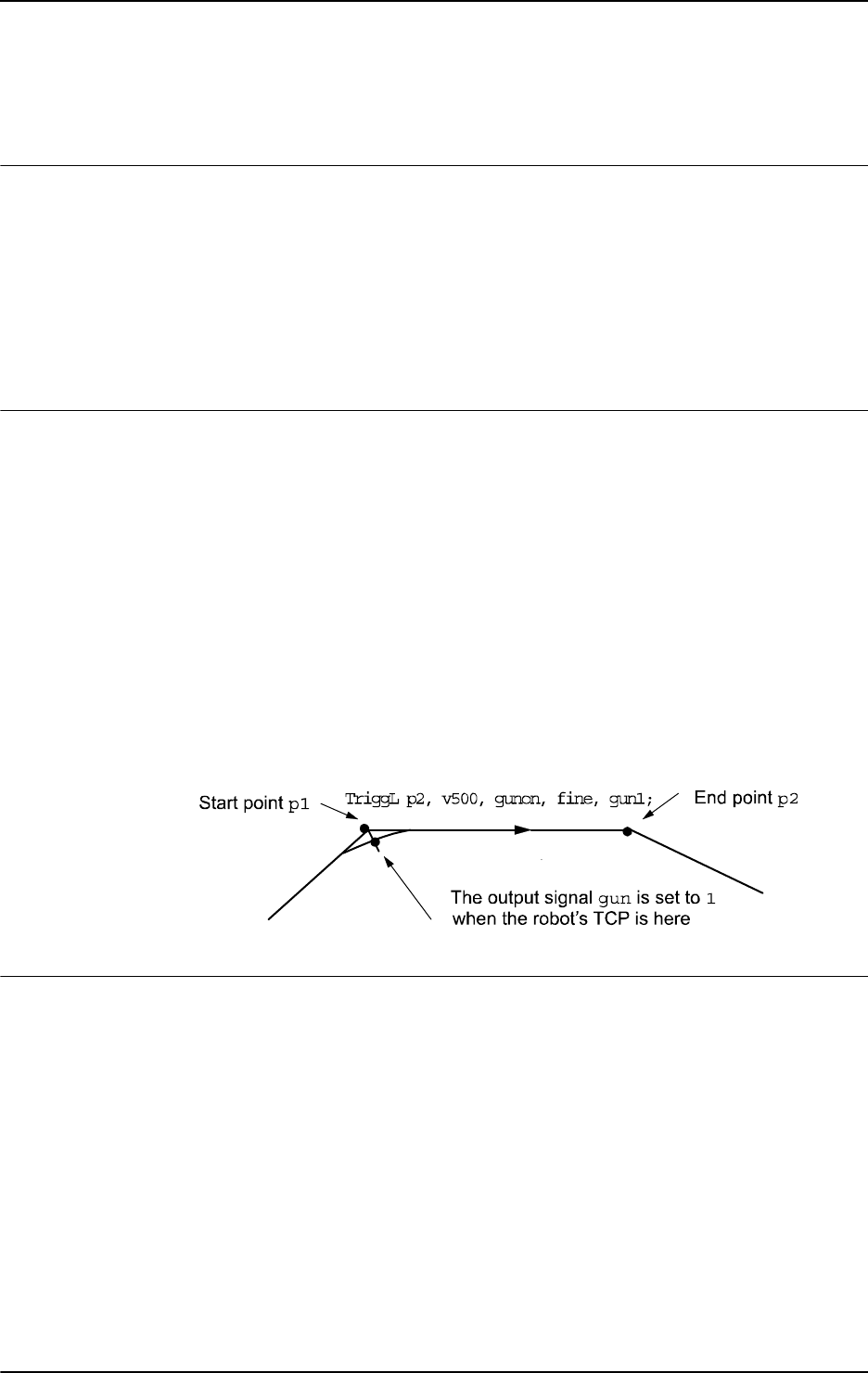
1 Instructions
1.212. TriggL - Linear robot movements with events
RobotWare - OS
6033HAC 16581-1 Revision: J
© Copyright 2004-2010 ABB. All rights reserved.
1.212. TriggL - Linear robot movements with events
Usage
TriggL (Trigg Linear) is used to set output signals and/or run interrupt routines at fixed
positions at the same time that the robot is making a linear movement.
One or more (max. 8) events can be defined using the instructions
TriggIO, TriggEquip,
TriggInt, TriggSpeed, TriggCheckIO, or TriggRampAO. Afterwards these definitions
are referred to in the instruction
TriggL.
This instruction can only be used in the main task
T_ROB1 or, if in a MultiMove system, in
Motion tasks.
Basic examples
Basic examples of the instruction
TriggL are illustrated below.
See also More examples on page 607.
Example 1
VAR triggdata gunon;
TriggIO gunon, 0 \Start \DOp:=gun, 1;
MoveJ p1, v500, z50, gun1;
TriggL p2, v500, gunon, fine, gun1;
The digital output signal gun is set when the robot’s TCP passes the midpoint of the corner
path of the point
p1.
The figure shows an example of fixed position I/O event.
xx0500002291
Arguments
TriggL [\Conc] ToPoint [\ID] Speed [\T] Trigg_1 [\T2] [\T3] [\T4]
[\T5] [\T6] [\T7] [\T8] Zone [\Inpos] Tool [\WObj] [\Corr]
[ \Conc ]
Concurrent
Data type:
switch
Subsequent instructions are executed while the robot is moving. The argument can be used to
avoid unwanted stops, caused by overloaded CPU, when using fly-by points. This is useful
when the programmed points are very close together at high speeds.
The argument is also useful when, for example, communicating with external equipment and
synchronization between the external equipment and robot movement is not required. It can
also be used to tune the execution of the robot path, to avoid warning 50024 Corner path
failure or error 40082 Deceleration limit.
Continues on next page

1 Instructions
1.212. TriggL - Linear robot movements with events
RobotWare - OS
3HAC 16581-1 Revision: J604
© Copyright 2004-2010 ABB. All rights reserved.
Using the argument \Conc, the number of movement instructions in succession is limited to
5. In a program section that includes
StorePath-RestoPath, movement instructions with
the argument
\Conc are not permitted.
If this argument is omitted and the
ToPoint is not a stop point then the subsequent instruction
is executed some time before the robot has reached the programmed zone.
This argument cannot be used in a coordinated synchronized movement in a MultiMove
System.
ToPoint
Data type: robtarget
The destination point of the robot and external axes. It is defined as a named position or stored
directly in the instruction (marked with an * in the instruction).
[ \ID ]
Synchronization id
Data type:
identno
This argument must be used in a MultiMove system, if it is a coordinated synchronized
movement, and is not allowed in any other cases.
The specified ID number must be the same in all cooperating program tasks. The ID number
gives a guarantee that the movements are not mixed up at runtime.
Speed
Data type: speeddata
The speed data that applies to movements. Speed data defines the velocity of the tool center
point, the external axes, and of the tool reorientation.
[ \T ]
Time
Data type:
num
This argument is used to specify the total time in seconds during which the robot moves. It is
then substituted for the corresponding speed data.
Trigg_1
Data type: triggdata
Variable that refers to trigger conditions and trigger activity defined earlier in the program
using the instructions
TriggIO, TriggEquip, TriggInt, TriggSpeed, TriggCheckIO or
TriggRampAO.
[ \T2 ]
Trigg 2
Data type:
triggdata
Variable that refers to trigger conditions and trigger activity defined earlier in the program
using the instructions
TriggIO, TriggEquip, TriggInt, TriggSpeed, TriggCheckIO,
or
TriggRampAO.
Continued
Continues on next page

1 Instructions
1.212. TriggL - Linear robot movements with events
RobotWare - OS
6053HAC 16581-1 Revision: J
© Copyright 2004-2010 ABB. All rights reserved.
[ \T3 ]
Trigg 3
Data type:
triggdata
Variable that refers to trigger conditions and trigger activity defined earlier in the program
using the instructions
TriggIO, TriggEquip, TriggInt, TriggSpeed, TriggCheckIO,
or
TriggRampAO.
[ \T4 ]
Trigg 4
Data type:
triggdata
Variable that refers to trigger conditions and trigger activity defined earlier in the program
using the instructions
TriggIO, TriggEquip, TriggInt, TriggSpeed, TriggCheckIO,
or
TriggRampAO.
[ \T5 ]
Trigg 5
Data type:
triggdata
Variable that refers to trigger conditions and trigger activity defined earlier in the program
using the instructions
TriggIO, TriggEquip, TriggInt, TriggSpeed, TriggCheckIO,
or
TriggRampAO.
[ \T6 ]
Trigg 6
Data type:
triggdata
Variable that refers to trigger conditions and trigger activity defined earlier in the program
using the instructions
TriggIO, TriggEquip, TriggInt, TriggSpeed, TriggCheckIO,
or
TriggRampAO.
[ \T7 ]
Trigg 7
Data type:
triggdata
Variable that refers to trigger conditions and trigger activity defined earlier in the program
using the instructions
TriggIO, TriggEquip, TriggInt, TriggSpeed, TriggCheckIO,
or
TriggRampAO.
[ \T8 ]
Trigg 8
Data type:
triggdata
Variable that refers to trigger conditions and trigger activity defined earlier in the program
using the instructions
TriggIO, TriggEquip, TriggInt, TriggSpeed, TriggCheckIO,
or
TriggRampAO.
Zone
Data type: zonedata
Zone data for the movement. Zone data describes the size of the generated corner path.
Continued
Continues on next page

1 Instructions
1.212. TriggL - Linear robot movements with events
RobotWare - OS
3HAC 16581-1 Revision: J606
© Copyright 2004-2010 ABB. All rights reserved.
[ \Inpos ]
In position
Data type:
stoppointdata
This argument is used to specify the convergence criteria for the position of the robot’s TCP
in the stop point. The stop point data substitutes the zone specified in the
Zone parameter.
Tool
Data type: tooldata
The tool in use when the robot moves. The tool center point is the point that is moved to the
specified destination position.
[ \WObj ]
Work Object
Data type:
wobjdata
The work object (coordinate system) to which the robot position in the instruction is related.
This argument can be omitted and if so then the position is related to the world coordinate
system. If, on the other hand, a stationary TCP or coordinated external axes are used then this
argument must be specified for a linear movement relative to the work object to be performed.
[ \Corr ]
Correction
Data type:
switch
Correction data written to a corrections entry by the instruction CorrWrite will be added to
the path and destination position if this argument is present.
Program execution
See the instruction
MoveL for information about linear movement.
As the trigger conditions are fulfilled when the robot is positioned closer and closer to the end
point, the defined trigger activities are carried out. The trigger conditions are fulfilled either
at a certain distance before the end point of the instruction, or at a certain distance after the
start point of the instruction, or at a certain point in time (limited to a short time) before the
end point of the instruction.
During stepping the execution forward, the I/O activities are carried out but the interrupt
routines are not run. During stepping the execution backwards, no trigger activities at all are
carried out.
Continued
Continues on next page

1 Instructions
1.212. TriggL - Linear robot movements with events
RobotWare - OS
6073HAC 16581-1 Revision: J
© Copyright 2004-2010 ABB. All rights reserved.
More examples
More examples of how to use the instruction
TriggL are illustrated below.
Example 1
VAR intnum intno1;
VAR triggdata trigg1;
...
CONNECT intno1 WITH trap1;
TriggInt trigg1, 0.1 \Time, intno1;
...
TriggL p1, v500, trigg1, fine, gun1;
TriggL p2, v500, trigg1, fine, gun1;
...
IDelete intno1;
The interrupt routine trap1 is run when the work point is at a position 0.1 s before the point
p1 or p2 respectively.
Error handling
If the programmed
ScaleValue argument for the specified analog output signal AOp in some
of the connected
TriggSpeed instructions results in out of limit for the analog signal
together with the programmed
Speed in this instruction, then the system variable ERRNO is
set to
ERR_AO_LIM.
If the programmed
DipLag argument in some of the connected TriggSpeed instructions is
too big in relation to the Event Preset Time used in System Parameters, then the system
variable
ERRNO is set to ERR_DIPLAG_LIM.
The system variable ERRNO can be set to ERR_NORUNUNIT if there is no contact with the
I/O unit when entering instruction and the used triggdata depends on a running I/O unit, i.e.
a signal is used in the triggdata.
These errors can be handled in the error handler.
Limitations
If the current start point deviates from the usual so that the total positioning length of the
instruction
TriggL is shorter than usual (e.g. at the start of TriggL with the robot position
at the end point) it may happen that several or all of the trigger conditions are fulfilled
immediately and at the same position. In such cases, the sequence in which the trigger
activities are carried out will be undefined. The program logic in the user program may not
be based on a normal sequence of trigger activities for an “incomplete movement”.
Continued
Continues on next page

1 Instructions
1.212. TriggL - Linear robot movements with events
RobotWare - OS
3HAC 16581-1 Revision: J608
© Copyright 2004-2010 ABB. All rights reserved.
Syntax
TriggL
[’\’ Conc ’,’]
[ ToPoint’ :=’ ] < expression (IN) of robtarget >
[ ’\’ ID ’:=’ < expression (IN) of identno >] ’,’
[ Speed ’:=’ ] < expression (IN) of speeddata >
[ ’\’ T ’:=’ < expression (IN) of num > ]’,’
[Trigg_1 ’:=’ ] < variable (VAR) of triggdata >
[ ’\’ T2 ’:=’ < variable (VAR) of triggdata > ]
[ ’\’ T3 ’:=’ < variable (VAR) of triggdata > ]
[ ’\’ T4 ’:=’ < variable (VAR) of triggdata > ]
[ ’\’ T5 ’:=’ < variable (VAR) of triggdata > ]
[ ’\’ T6 ’:=’ < variable (VAR) of triggdata > ]
[ ’\’ T7 ’:=’ < variable (VAR) of triggdata > ]
[ ’\’ T8 ’:=’ < variable (VAR) of triggdata > ] ´,’
[Zone ’:=’ ] < expression (IN) of zonedata >
[ ’\’ Inpos’ :=’ < expression (IN) of stoppointdata > ] ´,’
[ Tool ’:=’ ] < persistent (PERS) of tooldata >
[ ’\’ WObj’ :=’ < persistent (PERS) of wobjdata > ]
[ ’\’ Corr ] ’;’
Related information
For information about See
Circular movement with triggers TriggC - Circular robot movement with events on page
570
Joint movement with triggers TriggJ - Axis-wise robot movements with events on
page 597
Definition of triggers TriggIO - Define a fixed position or time I/O event near
a stop point on page 592
TriggEquip - Define a fixed position and time I/O event
on the path on page 582
TriggInt - Defines a position related interrupt on page
588
TriggCheckIO - Defines IO check at a fixed position on
page 577
TriggRampAO - Define a fixed position ramp AO event
on the path on page 616
TriggSpeed - Defines TCP speed proportional analog
output with fixed position-time scale event on page 622
Writes to a corrections entry CorrWrite - Writes to a correction generator on page 77
Linear movement Technical reference manual - RAPID overview, section
Motion and I/O principles - Positioning during program
execution
Definition of velocity speeddata - Speed data on page 1185
Definition of zone data zonedata - Zone data on page 1232
Definition of stop point data stoppointdata - Stop point data on page 1189
Definition of tools tooldata - Tool data on page 1207
Definition of work objects wobjdata - Work object data on page 1224
Continued
Continues on next page

1 Instructions
1.212. TriggL - Linear robot movements with events
RobotWare - OS
6093HAC 16581-1 Revision: J
© Copyright 2004-2010 ABB. All rights reserved.
Motion in general Technical reference manual - RAPID overview, section
Motion and I/O principles
For information about See
Continued
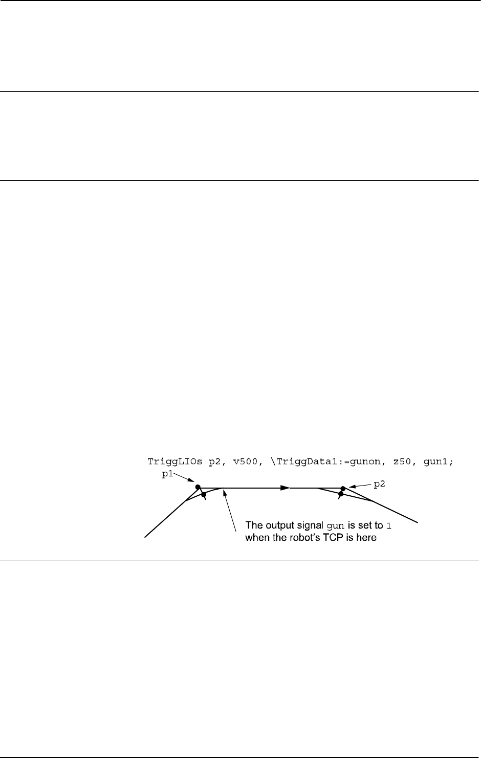
1 Instructions
1.213. TriggLIOs - Linear robot movements with I/O events
RobotWare - OS
3HAC 16581-1 Revision: J610
© Copyright 2004-2010 ABB. All rights reserved.
1.213. TriggLIOs - Linear robot movements with I/O events
Usage
TriggLIOs (Trigg Linear I/O) is used to set output signals at fixed positions at the same time
that the robot is making a linear movement.
The
TriggLIOs instruction is optimized to give good accuracy when using movements with
zones (compare with
TriggEquip/TriggL).
Basic examples
Basic examples of the instruction
TriggLIOs are illustrated below.
See also More examples on page 613.
Example 1
VAR triggios gunon{1};
gunon{1}.used:=TRUE;
gunon{1}.distance:=3;
gunon{1}.start:=TRUE;
gunon{1}.signalname:="gun";
gunon{1}.equiplag:=0;
gunon{1}.setvalue:=1;
MoveJ p1, v500, z50, gun1;
TriggLIOs p2, v500, \TriggData1:=gunon, z50, gun1;
MoveL p3, v500, z50, gun1;
The signal gun is set when the TCP is 3 mm after point p1.
The figure shows an example of a fixed position I/O event.
en0800000157
Arguments
TriggLIOs [\Conc] ToPoint [\ID] Speed [\T] [\TriggData1]
[\TriggData2] [\TriggData3] Zone [\Inpos] Tool [\WObj]
[\Corr]
[ \Conc ]
Concurrent
Data type:
switch
Subsequent instructions are executed while the robot is moving. The argument can be used to
avoid unwanted stops, caused by overloaded CPU, when using fly-by points. This is useful
when the programmed points are very close together at high speeds.
Continues on next page

1 Instructions
1.213. TriggLIOs - Linear robot movements with I/O events
RobotWare - OS
6113HAC 16581-1 Revision: J
© Copyright 2004-2010 ABB. All rights reserved.
The argument is also useful when, for example, communicating with external equipment and
synchronization between the external equipment and robot movement is not required. It can
also be used to tune the execution of the robot path, to avoid warning 50024 Corner path
failure or error 40082 Deceleration limit.
Using the argument
\Conc, the number of movement instructions in succession is limited to
5. In a program section that includes
StorePath-RestoPath, movement instructions with
the argument
\Conc are not permitted.
If this argument is omitted and the
ToPoint is not a stop point then the subsequent instruction
is executed some time before the robot has reached the programmed zone.
This argument cannot be used in a coordinated synchronized movement in a MultiMove
System.
ToPoint
Data type: robtarget
The destination point of the robot and external axes. It is defined as a named position or stored
directly in the instruction (marked with an * in the instruction).
[ \ID ]
Synchronization id
Data type:
identno
This argument must be used in a MultiMove system, if it is a coordinated synchronized
movement, and is not allowed in any other cases.
The specified ID number must be the same in all cooperating program tasks. The ID number
gives a guarantee that the movements are not mixed up at runtime.
Speed
Data type: speeddata
The speed data that applies to movements. Speed data defines the velocity of the tool center
point, the external axes, and of the tool reorientation.
[ \T ]
Time
Data type:
num
This argument is used to specify the total time in seconds during which the robot moves. It is
then substituted for the corresponding speed data.
[\TriggData1]
Data type: array of triggios
Variable (array) that refers to trigger conditions and trigger activity. When using this
argument, it is possible to set analog output signals, digital output signals and digital group
output signals. If using a digital group output signal there is a limitation on 23 signals in the
group.
Continued
Continues on next page

1 Instructions
1.213. TriggLIOs - Linear robot movements with I/O events
RobotWare - OS
3HAC 16581-1 Revision: J612
© Copyright 2004-2010 ABB. All rights reserved.
[\TriggData2]
Data type: array of triggstrgo
Variable (array) that refers to trigger conditions and trigger activity. When using this
argument, it is possible to set digital group output signals that consists of 32 signals in the
group and can have a maximum set value of 4294967295. Only digital group output signals
can be used.
[\TriggData3]
Data type: array of triggiosdnum
Variable (array) that refers to trigger conditions and trigger activity. When using this
argument, it is possible to set analog output signals, digital output signals and digital group
output signals that consists of 32 signals in the group and can have a maximum set value of
4294967295.
Zone
Data type: zonedata
Zone data for the movement. Zone data describes the size of the generated corner path.
[ \Inpos ]
In position
Data type:
stoppointdata
This argument is used to specify the convergence criteria for the position of the robot’s TCP
in the stop point. The stop point data substitutes the zone specified in the
Zone parameter.
Tool
Data type: tooldata
The tool in use when the robot moves. The tool center point is the point that is moved to the
specified destination position.
[ \WObj ]
Work Object
Data type:
wobjdata
The work object (coordinate system) to which the robot position in the instruction is related.
This argument can be omitted and if so then the position is related to the world coordinate
system. If, on the other hand, a stationary TCP or coordinated external axes are used then this
argument must be specified for a linear movement relative to the work object to be performed.
[ \Corr ]
Correction
Data type:
switch
Correction data written to a corrections entry by the instruction CorrWrite will be added to
the path and destination position if this argument is present.
Continued
Continues on next page

1 Instructions
1.213. TriggLIOs - Linear robot movements with I/O events
RobotWare - OS
6133HAC 16581-1 Revision: J
© Copyright 2004-2010 ABB. All rights reserved.
Program execution
See the instruction
MoveL for information about linear movement.
With the instruction
TriggLIOs it is possible to setup 1-50 different trigger activities on I/O
signals along a path from A to B. The signals that can be used are digital output signals, digital
group output signals and analog output signals. The trigger conditions are fulfilled either at a
certain distance before the end point of the instruction, or at a certain distance after the start
point of the instruction.
The instruction requires use of either
TriggData1, TriggData2 or TriggData3 argument
or all three of them. Use of any of the triggs is optional though. To inhibit use of a trigg the
component
used can be set to FALSE in the array element of the data types triggios/
triggstrgo/triggiosdnum. If no array element is in use, then the TriggLIOs instruction
will behave as a
MoveL, and no I/O activities will be carried out.
If stepping the program forward, the I/O activities are carried out. During stepping the
execution backwards, no I/O activities at all are carried out.
If setting component
EquipLag in TriggData1, TriggData2 or TriggData3 argument to
a negative time (delay), the I/O signal can be set after the destination point (
ToPoint).
If using the argument
TriggData2 or TriggData3 it is possible to use values up to
4294967295, which is the maximum value a group of digital signals can have (32 signals in
a group signal is max for the system).
More examples
More examples of how to use the instruction
TriggLIOs are illustrated below.
Example 1
VAR triggios mytriggios{3}:= [[TRUE, 3, TRUE, 0, "go1", 55, 0],
[TRUE, 15, TRUE, 0, "ao1", 10, 0], [TRUE, 3, FALSE, 0, "do1",
1, 0]];
...
MoveL p1, v500, z50, gun1;
TriggLIOs p2, v500, \TriggData1:=mytriggios, z50, gun1;
MoveL p3, v500, z50, gun1;
The digital group output signal go1 will be set to value 55 3 mm from p1. Analog output
signal will be set to value 10 15 mm from
p1. Digital output signal do1 will be set 3 mm from
ToPoint
p2.
Continued
Continues on next page

1 Instructions
1.213. TriggLIOs - Linear robot movements with I/O events
RobotWare - OS
3HAC 16581-1 Revision: J614
© Copyright 2004-2010 ABB. All rights reserved.
Example 2
VAR triggios mytriggios{3}:= [[TRUE, 3, TRUE, 0, "go1", 55, 0],
[TRUE, 15, TRUE, 0, "ao1", 10, 0], [TRUE, 3, FALSE, 0, "do1",
1, 0]];
VAR triggstrgo mytriggstrgo{3}:= [[TRUE, 3, TRUE, 0, "go2", "1",
0], [TRUE, 15, TRUE, 0, "go2", "800000", 0], [TRUE, 4, FALSE,
0, "go2", "4294967295", 0]];
VAR triggiosdnum mytriggiosdnum{3}:= [[TRUE, 10, TRUE, 0, "go3",
4294967295, 0], [TRUE, 10, TRUE, 0, "ao2", 5, 0], [TRUE, 10,
TRUE, 0, "do2", 1, 0]];
...
MoveL p1, v500, z50, gun1;
TriggLIOs p2, v500, \TriggData1:=mytriggios \TriggData2:=
mytriggstrgo \TriggData3:=mytriggiosdnum, z50, gun1;
MoveL p3, v500, z50, gun1;
The digital group output signal go1 will be set to value 55 3 mm from p1. Analog output
signal
ao1 will be set to value 10 15 mm from p1. Digital output signal do1 will be set 3 mm
from
ToPoint p2. Those position events is setup by variable mytriggios. The variable
mytriggstrgo sets up position events to occur 3 and 15 mm from p1. First the signal go2
is set to 1, then it is set to 800000. The signal will be set to value 4294967295 4 mm from the
ToPoint p2. This is the maximum value for a 32 bits digital output signal. The variable
mytriggiosdnum sets up three position events to occur 10 mm from p1. First the signal go3
is set to 4294967295, then
ao2 is set to 5 and last do2 is set to 1.
Error handling
The following recoverable error can be generated. The error can be handled in an error
handler. The system variable
ERRNO will be set to:
ERR_NORUNUNIT
if there is no contact with the I/O unit.
ERR_GO_LIM
if the programmed setvalue argument for the specified digital group output signal
signalname is outside limits. (Declared in TriggData1, TriggData2 or TriggData3)
ERR_AO_LIM
if the programmed setvalue argument for the specified analog output signal signalname
is outside limits. (Declared in
TriggData1 or TriggData3)
Limitations
If the current start point deviates from the usual so that the total positioning length of the
instruction
TriggLIOs is shorter than usual (e.g. at the start of TriggLIOs with the robot
position at the end point) it may happen that several or all of the trigger conditions are fulfilled
immediately and at the same position. In such cases, the sequence in which the trigger
activities are carried out will be undefined. The program logic in the user program may not
be based on a normal sequence of trigger activities for an “incomplete movement”.
Continued
Continues on next page

1 Instructions
1.213. TriggLIOs - Linear robot movements with I/O events
RobotWare - OS
6153HAC 16581-1 Revision: J
© Copyright 2004-2010 ABB. All rights reserved.
The limitation of the number of triggs in the instruction TriggLIOs is 50 for each
programmed instruction. However, if those triggs is supposed to happen in a close distance,
the system might not be able to handle that. That depends on how the movement is done, TCP
speed used and how close the triggs are programmed. Those limitations exists, but it is hard
to predict when those problems will occur.
Syntax
TriggLIOs
[’\’ Conc ’,’]
[ ToPoint’ :=’ ] < expression (IN) of robtarget >
[ ’\’ ID ’:=’ < expression (IN) of identno >] ’,’
[ Speed ’:=’ ] < expression (IN) of speeddata >
[ ’\’ T ’:=’ < expression (IN) of num > ]’,’
[ ’\’ TriggData1’ :=’ ] < array {*} (VAR) of triggios >
[ ’\’ TriggData2’ :=’ ] < array {*} (VAR) of triggstrgo >
[ ’\’ TriggData3’ :=’ ] < array {*} (VAR) of triggiosdnum >
[Zone ’:=’ ] < expression (IN) of zonedata >
[ ’\’ Inpos’ :=’ < expression (IN) of stoppointdata > ] ´,’
[ Tool ’:=’ ] < persistent (PERS) of tooldata >
[ ’\’ WObj’ :=’ < persistent (PERS) of wobjdata > ]
[ ’\’ Corr ] ’;’
Related information
For information about See
Storage of trigg conditions and trigger activity triggios - Positioning events, trigg on page
1214
Storage of trigg conditions and trigger activity
for digital signal group consisting of 32
signals
triggstrgo - Positioning events, trigg on page
1219
Storage of trigg conditions and trigger activity triggiosdnum - Positioning events, trigg on
page 1217
Linear movement Technical reference manual - RAPID
overview, section Motion and I/O principles -
Positioning during program execution
Motion in general Technical reference manual - RAPID
overview, section Motion and I/O principles
Continued

1 Instructions
1.214. TriggRampAO - Define a fixed position ramp AO event on the path
RobotWare - OS
3HAC 16581-1 Revision: J616
© Copyright 2004-2010 ABB. All rights reserved.
1.214. TriggRampAO - Define a fixed position ramp AO event on the path
Usage
TriggRampAO (Trigg Ramp Analog Output) is used to define conditions and actions for
ramping up or down analog output signal value at a fixed position along the robot’s movement
path with possibility to do time compensation for the lag in the external equipment.
The data defined is used for implementation in one or more subsequent
TriggL, TriggC, or
TriggJ instructions. Beside these instructions, TriggRampAO can also be used in CapL or
CapC instructions.
The type of trig actions connected to the same
TriggL/C/J instruction can be TriggRampAO
or any of
TriggIO, TriggEquip, TriggSpeed, TriggInt, or TriggCheckIO
instructions. Any type of combination is allowed except that only one
TriggSpeed action on
the same signal in the same
TriggL/C/J instruction is allowed.
This instruction can only be used in the main task
T_ROB1 or, if in a MultiMove system, in
Motion tasks.
Basic examples
Basic examples of the instruction
TriggRampAO are illustrated below.
See also More examples on page 620.
Example 1
VAR triggdata ramp_up;
...
TriggRampAO ramp_up, 0 \Start, 0.1, aolaser1, 8, 15;
MoveL p1, v200, z10, gun1;
TriggL p2, v200, ramp_up, z10, gun1;
The analog signal aolaser1 will start ramping up its logical value from current value to the
new value
8, when the TCP of the tool gun1 is 0,1 s before the centre of the corner path at
p1. The whole ramp-up will be done while the robot moves 15 mm.
Example 2
VAR triggdata ramp_down;
...
TriggRampAO ramp_down, 15, 0.1, aolaser1, 2, 10;
MoveL p3, v200, z10, gun1;
TriggL p4, v200, ramp_down, z10, gun1;
The analog signal aolaser1 will start ramping down its logical value from current value to
the new value
2, when the TCP of the tool gun1 is 15 mm plus 0,1 s before the centre of the
corner path at
p4. The whole ramp-down will be done while the robot moves 10 mm.
Continues on next page
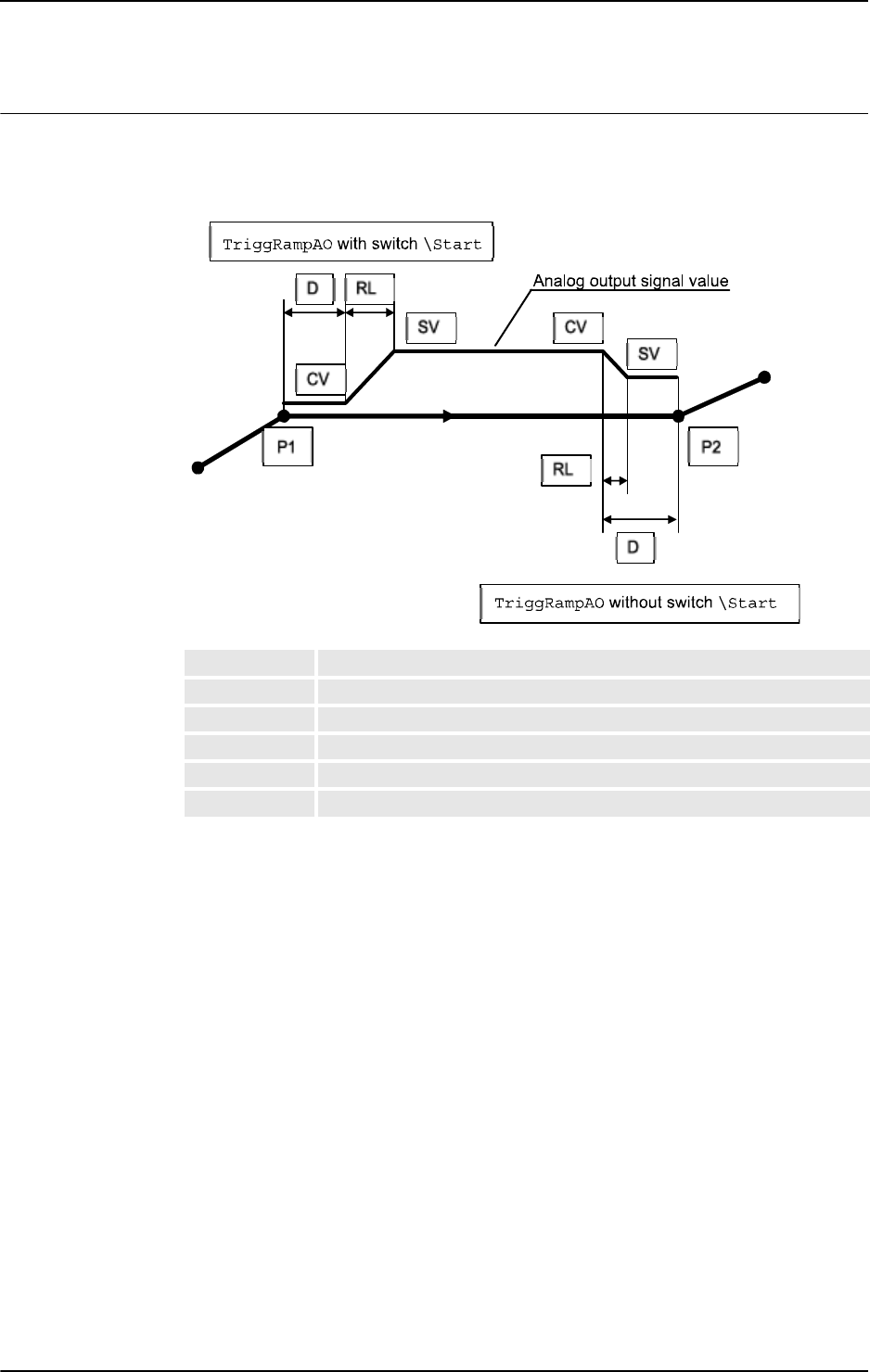
1 Instructions
1.214. TriggRampAO - Define a fixed position ramp AO event on the path
RobotWare - OS
6173HAC 16581-1 Revision: J
© Copyright 2004-2010 ABB. All rights reserved.
Arguments
TriggRampAO TriggData Distance [\Start] EquipLag AOutput SetValue
RampLength [\Time]
xx0600003433
TriggData
Data type: triggdata
Variable for storing of the triggdata returned from this instruction. These triggdata can
then be used in the subsequent
TriggL, TriggC , TriggJ, CapL, or CapC instructions.
Distance
Data type: num
Defines the distance from the centre of the corner path where the ramp of the analog output
shall start.
Specified as the distance in mm (positive value) from the end point (
ToPoint) of the
movement path (applicable if the argument
\Start is not set).
See the section Program Execution for further details.
[\Start]
Data type: switch
Used when the distance for the argument Distance is related to the movement start point
(preceding
ToPoint) instead of the end point.
D Parameter Distance
RL Parameter RampLength
CV Current analog signal Value
SV Parameter SetValue for the analog signal value
P1 ToPoint for preceding move instruction
P2 ToPoint for actual TrigL/C/J instruction
Continued
Continues on next page
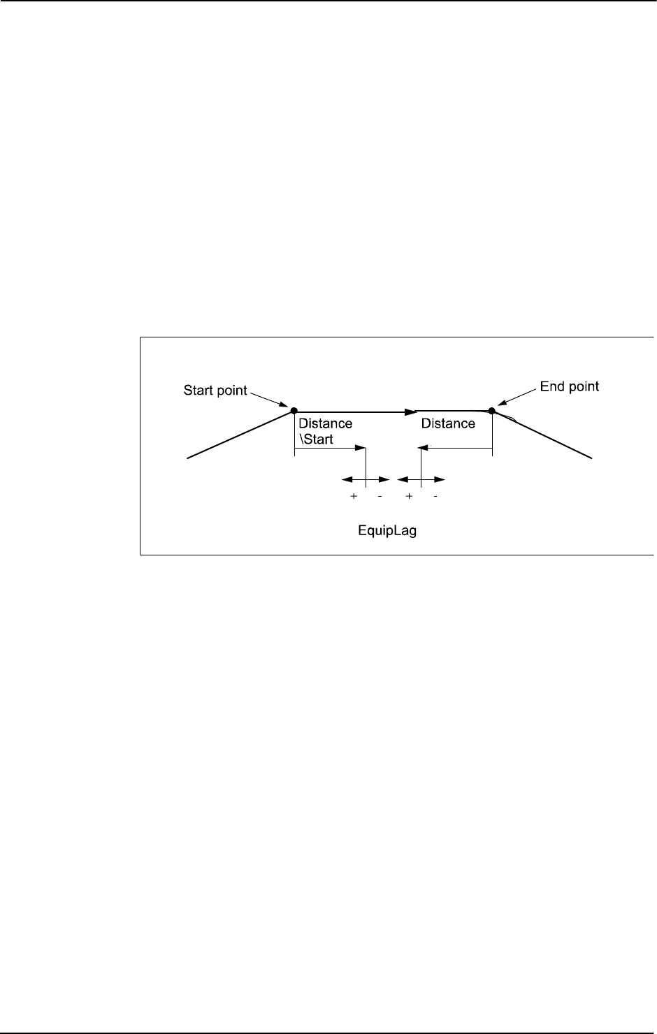
1 Instructions
1.214. TriggRampAO - Define a fixed position ramp AO event on the path
RobotWare - OS
3HAC 16581-1 Revision: J618
© Copyright 2004-2010 ABB. All rights reserved.
EquipLag
Equipment Lag
Data type:
num
Specify the lag for the external equipment in s.
For compensation of external equipment lag, use positive argument value. Positive argument
value means that the start of the ramping of the
AO signal is done by the robot system at a
specified time before the
TCP physically reaches the specified distance point in relation to the
movement start or end point.
Negative argument value means that starting the ramping of the
AO signal is done by the robot
system at a specified time. After that, the
TCP has physically passed the specified distance
point in relation to the movement start or end point.
The figure shows use of argument
EquipLag.
xx0500002262
AOutput
Analog Output
Data type:
signalao
The name of the analog output signal.
SetValue
Data type: num
The value to which the analog output signal should be ramped up or down to (must be within
the allowed logical range value for the signal). The ramping is started with the current value
of the analog output signal.
RampLength
Data type: num
The ramping length in mm along the TCP movement path.
[\Time]
Data type: switch
Used then the RampLength specifies the ramp time in s instead of ramping length.
Must be used, if subsequent
TriggL, TriggC, or TriggJ specifies that the total movement
should be done on time (argument
\T) instead of speed.
Continued
Continues on next page
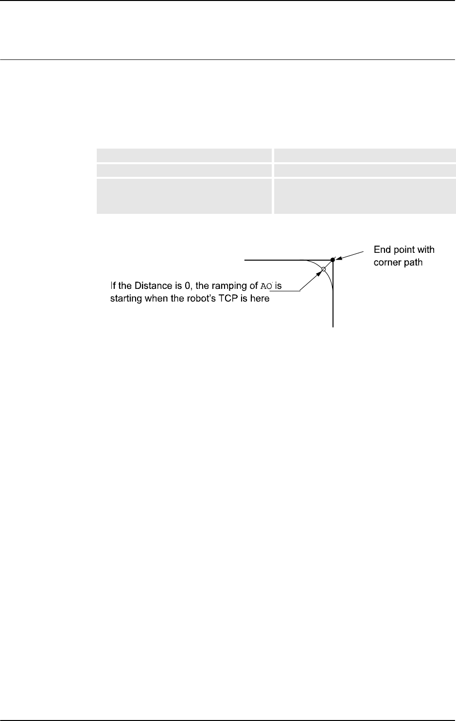
1 Instructions
1.214. TriggRampAO - Define a fixed position ramp AO event on the path
RobotWare - OS
6193HAC 16581-1 Revision: J
© Copyright 2004-2010 ABB. All rights reserved.
Program execution
When running the instruction
TriggRampAO, the trigger condition is stored in the specified
variable for the argument
TriggData.
Afterwards, when one of the instructions
TriggL, TriggC or TriggJ is executed, the
following are applicable with regard to the definitions in
TriggRampAO:
The table describes the distance specified in the argument
Distance:
The figure shows ramping of
AO in a corner path.
xx0600003439
Program execution characteristics of TriggRampAO connected to any TriggL/C/J:
• The ramping of the AO is started when the robot reaches the specified Distance point
on the robot path (with compensation for the specified
EquipLag)
• The ramping function will be performed during a time period calculated from
specified
RampLength and the programmed TCP speed. The calculation takes into
cosideration
VelSet, manual speed override, and max. 250 mm/s in MAN mode but not
any other speed limitations.
• Updating of the AO signal value from start (current read) value to specified SetValue
will be done each 10 ms resulting in a staircase form. If the calculated ramp time or
specified ramp time is greater than 0.5 s then the ramping frequency will slow down:
• <= 0,5s gives max. 50 step each 10 ms
• <= 1s gives max. 50 steps each 20 ms
• <= 1,5s gives max. 50 steps each 30 ms and so on
The
TriggRampAO action is also done in FWD step but not in BWD step mode.
At any type of stop (ProgStop, Emergency Stop …) if the ramping function is active for the
occasion:
- if ramping up, the
AO is set to an old value momentarily.
- if ramping down, the
AO is set to the new SetValue momentarily.
Linear movement The straight line distance
Circular movement The circle arc length
Non-linear movement The approximate arc length along the path (to
obtain adequate accuracy, the distance should
not exceed one half of the arc length).
Continued
Continues on next page

1 Instructions
1.214. TriggRampAO - Define a fixed position ramp AO event on the path
RobotWare - OS
3HAC 16581-1 Revision: J620
© Copyright 2004-2010 ABB. All rights reserved.
More examples
More examples of how to use the instruction
TriggRampAO are illustrated below.
Example 1
VAR triggdata ramp_up;
VAR triggdata ramp_down;
...
TriggRampAO ramp_up, 0 \Start, 0.1, aolaser1, 8, 15;
TriggRampAO ramp_down, 15, 0.1, aolaser1, 2, 10;
MoveL p1, v200, z10, gun1;
TriggL p2, v200, ramp_up, \T2:=ramp_down, z10, gun1;
In this example both the ramp-up and ramp-down of the AO is done in the same TriggL
instruction on the same movement path. It works without any interference of the
AO settings
if the movement path is long enough.
The analog signal
aolaser1 will start ramping up its logical value from the current value to
the new value
8 when the TCP of the tool gun1 is 0,1 s before the centre of the corner path at
p1. The whole ramp-up will be done while the robot moves 15 mm.
The analog signal
aolaser1 will start ramping down its logical value from the current value
8
to the new value 2 when the TCP of the tool gun1 is 15 mm plus 0,1 s before the centre
of the corner path at
p2. The whole ramp-up will be done while the robot moves 10 mm.
Error handling
If the programmed
SetValue argument for the specified analog output signal AOutput is
out of limit then the system variable
ERRNO is set to ERR_AO_LIM. This error can be handled
in the error handler.
Limitations
The analog output signal value will not be compensated for lower
TCP-speed in corner path
or during other acceleration or deceleration phases (the
AO is not TCP speed proportional).
Only the start point of the
AO ramping will be done at the specified position on the path. The
ramping up or down will be done with “dead calculation”, with high accuracy:
• At constant speed the deviation for the end of the AO ramping compared with the
specified will be low.
• During acceleration or deceleration phases, such as near stop points, the deviation will
be higher.
• Recommendation: use corner paths before ramp up and after ramp down.
If use of two or several
TriggRampAO on the same analog output signal and connected to the
same
TriggL/C/J instrucion and both or several RampLength are located on the same part
of the robot path then the
AO settings will interact with each other.
The position (+/- time) related ramp
AO event will start when the previous ToPoint is passed
if the specified
Distance from the actual ToPoint is not within the length of movement for
the current
TriggL/C/J instruction. The position (+/- time) related ramp AO event will start
when the actual
ToPoint is passed if the specified Distance from the previous ToPoint is
not within the length of movement for the current
TriggL/C/J instruction (with argument
\Start
).
Continued
Continues on next page

1 Instructions
1.214. TriggRampAO - Define a fixed position ramp AO event on the path
RobotWare - OS
6213HAC 16581-1 Revision: J
© Copyright 2004-2010 ABB. All rights reserved.
No support for restart of the ramping AO function after any type of stop (ProgStop, Emergency
Stop …).
At Power Fail Restart the
TriggL/C/J instruction is started from the beginning of the current
Power Fail position.
Syntax
TriggRampAO
[ TriggData ’:=’ ] < variable (VAR) of triggdata > ‘,‘
[ Distance‘ :=’ ] < expression (IN) of num >
[ ‘\’ Start ]‘ ,’
[ EquipLag’ :=’ ] < expression (IN) of num > ‘,‘
[ AOutput ‘:=’ ] < variable (VAR) of signalao>‘ ,’
[ SetValue ‘:=’ ] < expression (IN) of num>‘ ,‘
[ RampLength ‘:=’ ] < expression (IN) of num>‘ ,‘
[ ‘\’ Time ]‘ ;’
Related information
For information about See
Use of triggers TriggL - Linear robot movements with events
on page 603
TriggC - Circular robot movement with events
on page 570
TriggJ - Axis-wise robot movements with
events on page 597
Definition of other triggs TriggEquip - Define a fixed position and time
I/O event on the path on page 582
Storage of triggdata triggdata - Positioning events, trigg on page
1213
Set of analog output signal SetAO - Changes the value of an analog
output signal on page 431
signalxx - Digital and analog signals on page
1181
Configuration of event preset time Technical reference manual - System
parameters, section Motion
Continued
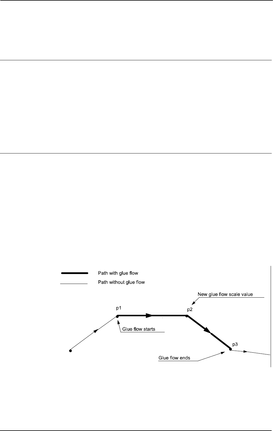
1 Instructions
1.215. TriggSpeed - Defines TCP speed proportional analog output with fixed position-time scale event
RobotWare - OS
3HAC 16581-1 Revision: J622
© Copyright 2004-2010 ABB. All rights reserved.
1.215. TriggSpeed - Defines TCP speed proportional analog output with fixed
position-time scale event
Usage
TriggSpeed is used to define conditions and actions for control of an analog output signal
with output value proportional to the actual TCP speed. The beginning, scaling, and ending
of the analog output can be specified at a fixed position-time along the robot’s movement
path. It is possible to use time compensation for the lag in the external equipment for the
beginning, scaling, and ending of the analog output and also for speed dips of the robot.
The data defined is used in one or more subsequent
TriggL, TriggC, or TriggJ
instructions.
This instruction can only be used in the main task
T_ROB1, if in a MultiMove System, in
Motion tasks.
Basic examples
Basic examples of the instruction
TriggSpeed are illustrated below.
See also More examples on page 626.
Example 1
VAR triggdata glueflow;
TriggSpeed glueflow, 0, 0.05, glue_ao, 0.8\DipLag=:0.04
\ErrDO:=glue_err;
TriggL p1, v500, glueflow, z50, gun1;
TriggSpeed glueflow, 10, 0.05, glue_ao, 1;
TriggL p2, v500, glueflow, z10, gun1;
TriggSpeed glueflow, 0, 0.05, glue_ao, 0;
TriggL p3, v500, glueflow, z50, gun1;
The figure below illustrates an example of TriggSpeed sequence
xx0500002329
The glue flow (analog output glue_ao) with scale value 0.8 starts when TCP is 0.05 s
before point
p1, new glue flow scale value 1 when TCP is 10 mm plus 0.05 s before point
p2, and the glue flow ends (scale value 0) when TCP is 0.05 s before point p3.
Any speed dip by the robot is time compensated in such a way that the analog output signal
glue_ao is affected 0.04 s before the TCP speed dip occurs.
Continues on next page

1 Instructions
1.215. TriggSpeed - Defines TCP speed proportional analog output with fixed position-time scale event
RobotWare - OS
6233HAC 16581-1 Revision: J
© Copyright 2004-2010 ABB. All rights reserved.
If overflow of the calculated logical analog output value in glue_ao then the digital output
signal
glue_err is set. If there is no more overflow then glue_err is reset.
Arguments
TriggSpeed TriggData Distance [\Start] ScaleLag AOp ScaleValue
[\DipLag] [\ErrDO] [\Inhib]
TriggData
Data type: triggdata
Variable for storing the triggdata returned from this instruction. These triggdata are
then used in the subsequent
TriggL, TriggC, or TriggJ instructions.
Distance
Data type: num
Defines the position on the path for change of the analog output value.
Specified as the distance in mm (positive value) from the end point of the movement path
(applicable if the argument \
Start is not set).
See Program execution on page 625 for further details.
[ \Start ]
Data type: switch
Used when the distance for the argument Distance starts at the movement’s start point
instead of the end point.
ScaleLag
Data type: num
Specify the lag as time in s (positive value) in the external equipment for change of the analog
output value (starting, scaling, and ending).
For compensation of external equipment lag, this argument value means that the analog
output signal is set by the robot at a specified time before the TCP physically reaches the
specified distance in relation to the movement’s start or end point.
The argument can also be used to extend the analog output beyond the end point. Set the time
in seconds that the robot shall keep the analog output. Set the time with a negative sign. The
limit is -0.10 seconds.
The figure below illustrates the use of argument
ScaleLag
xx0500002330
Continued
Continues on next page

1 Instructions
1.215. TriggSpeed - Defines TCP speed proportional analog output with fixed position-time scale event
RobotWare - OS
3HAC 16581-1 Revision: J624
© Copyright 2004-2010 ABB. All rights reserved.
AOp
Analog Output
Data type:
signalao
The name of the analog output signal.
ScaleValue
Data type: num
The scale value for the analog output signal.
The physical output value for the analog signal is calculated by the robot:
• Logical output value = Scale value * Actual TCP speed in mm/s.
• Physical output value = According definition in configuration for actual analog output
signal with above Logical output value as input.
[ \DipLag ]
Data type: num
Specify the lag as time in s (positive value) for the external equipment when changing of the
analog output value due to robot speed dips.
For compensation of external equipment lag, this argument value means that the analog
output signal is set by the robot at a specified time before the TCP speed dip occurs.
This argument can only be used by the robot for the first
TriggSpeed (in combination with
one of
TriggL, TriggC, or TriggJ) in a sequence of several TriggSpeed instructions. The
first specified argument value is valid for all the following
TriggSpeed in the sequence.
[ \ErrDO ]
Error Digital Output
Data type:
signaldo
The name of the digital output signal for reporting analog value overflow.
If during movement the calculation of the logical analog output value for signal in argument
AOp results in overflow due to overspeed then this signal is set and the physical analog output
value is reduced to the maximum value. If there is no more overflow then the signal is reset.
This argument can only be used by the robot for the 1st
TriggSpeed (in combination with
one of
TriggL, TriggC, or TriggJ) in a sequence of several TriggSpeed instructions. The
1st given argument value is valid for all the following
TriggSpeed in the sequence.
[ \Inhib ]
Inhibit
Data type:
bool
The name of a persistent variable flag for inhibiting the setting of the analog signal at runtime.
If this optional argument is used and the actual value of the specified flag is
TRUE at the time
for setting the analog signal then the specified signal
AOp will be set to 0 instead of a
calculated value.
This argument can only be used by the robot for the 1st
TriggSpeed (in combination with
one of
TriggL, TriggC, or TriggJ) in a sequence of several TriggSpeed instructions. The
1st given argument value is valid for all the following
TriggSpeed in the sequence.
Continued
Continues on next page
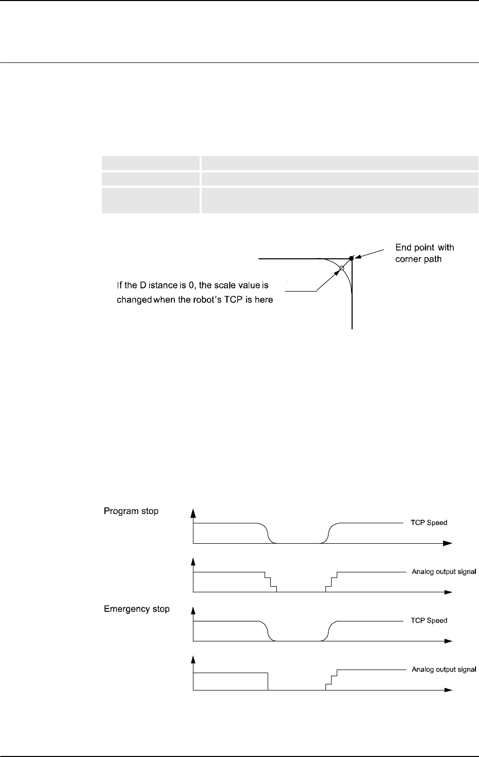
1 Instructions
1.215. TriggSpeed - Defines TCP speed proportional analog output with fixed position-time scale event
RobotWare - OS
6253HAC 16581-1 Revision: J
© Copyright 2004-2010 ABB. All rights reserved.
Program execution
When running the instruction
TriggSpeed the trigger condition is stored in the specified
variable for the argument
TriggData.
Afterwards, when one of the instructions
TriggL, TriggC, or TriggJ is executed then the
following are applicable with regard to the definitions in
TriggSpeed:
For the distance specified in the argument
Distance, see the table below.:
The figure below illustrates the fixed position-time scale value event on a corner path.
xx0500002331
The position-time related scale value event will be generated when the start point (end point)
is passed if the specified distance from the end point (start point) is not within the length of
the movement of the current instruction (
TriggL, TriggC, or TriggJ).
The 1:st
TriggSpeed used by one of TriggL, TriggC, or TriggJ instruction will internally
in the system create a process with the same name as the analog output signal. The same
process will be used by all succeeding
TriggL, TriggC, or TriggJ which refers to same
signal name and setup by a
TriggSpeed instruction.
The process will immediately set the analog output to 0, in the event of a program emergency
stop. In the event of a program stop, the analog output signal will stay TCP-speed
proportional until the robot stands still. The process keeps “alive” and ready for a restart.
When the robot restarts, the signal is TCP-speed proportional directly from the start.
xx0500002332
The process will “die” after handling a scale event with value 0 if no succeeding TriggL,
TriggC, or TriggJ is in the queue at the time.
Linear movement The straight line distance
Circular movement The circle arc length
Non-linear movement The approximate arc length along the path (to obtain adequate
accuracy, the distance should not exceed one half of the arc length).
Continued
Continues on next page
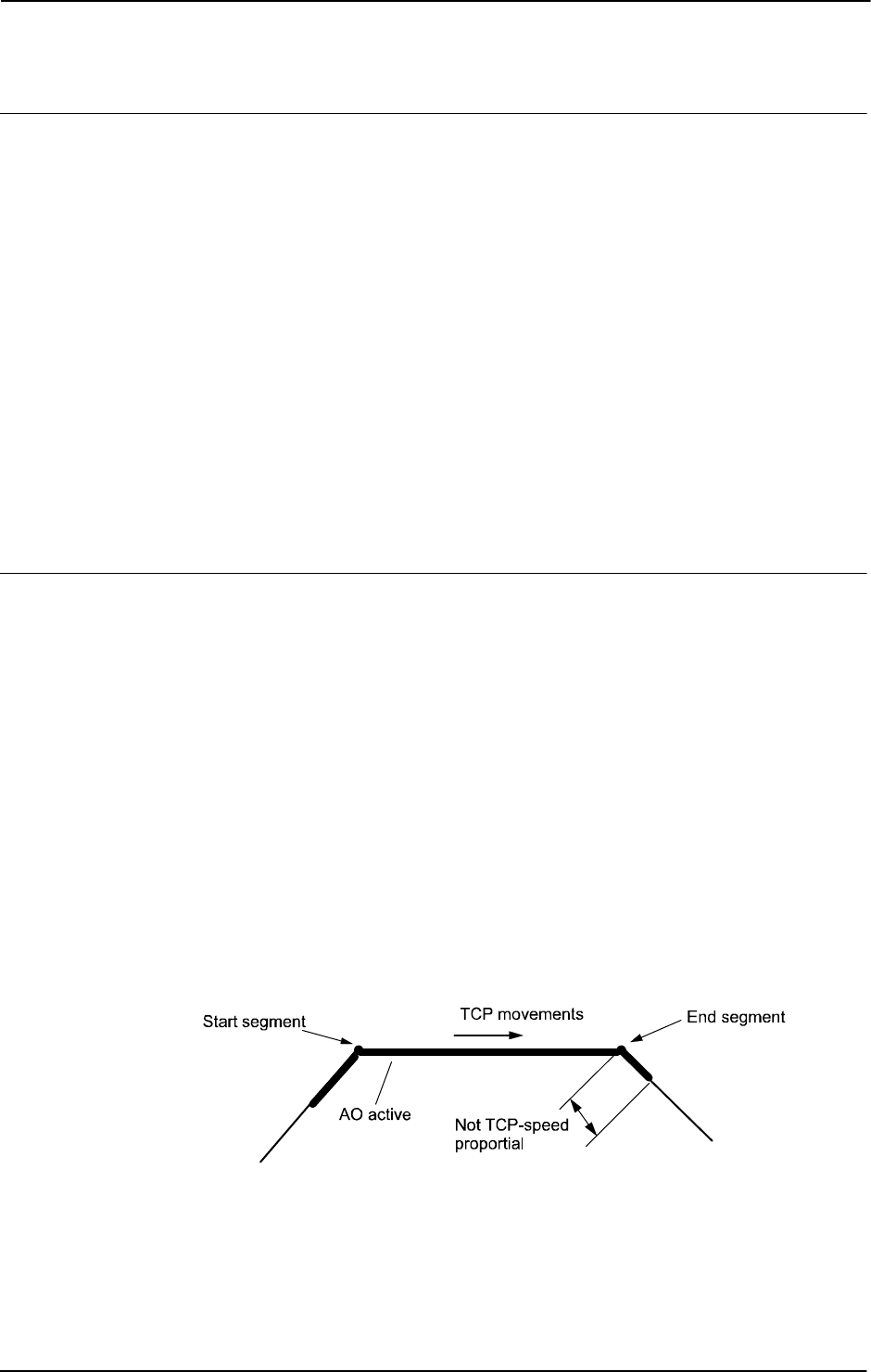
1 Instructions
1.215. TriggSpeed - Defines TCP speed proportional analog output with fixed position-time scale event
RobotWare - OS
3HAC 16581-1 Revision: J626
© Copyright 2004-2010 ABB. All rights reserved.
More examples
More examples of the instruction
TriggSpeed are illustrated below.
Example 1
VAR triggdata flow;
TriggSpeed flow, 10 \Start, 0.05, flowsignal, 0.5 \DipLag:=0.03;
MoveJ p1, v1000, z50, tool1;
TriggL p2, v500, flow, z50, tool1;
The analog output signal flowsignal is set to a logical value = (0.5 * actual TCP speed in
mm/s)
0.05 s before the TCP passes a point located 10 mm after the start point p. The
output value is adjusted to be proportional to the actual TCP speed during the movement to
p2.
...
TriggL p3, v500, flow, z10, tool1;
The robot moves from p2 to p3 with the analog output value proportional to the actual TCP
speed. The analog output value will be decreased at time
0.03 s before the robot reduces the
TCP speed during the passage of the corner path
z10.
Limitations
The limitations for the instruction
TriggSpeed are illustrated below.
Accuracy of position-time related scale value event
Typical absolute accuracy values for scale value events ±5 ms.
Typical repeat accuracy values for scale value events ±2 ms.
Accuracy of TCP speed dips adaptation (deceleration - acceleration phases)
Typical absolute accuracy values for TCP speed dips adaptation ±5 ms.
Typical repeat accuracy values for TCP speed dips adaptation ±2ms (the value depends of the
configured Path resolution).
Negative ScaleLag
If a negative value on parameter ScaleLag is used to move the zero scaling over to the next
segment then the analog output signal will not be reset if a program stop occurs. An
emergency stop will always reset the analog signal.
The analog signal is no longer TCP-speed proportional after the end point on the segment.
xx0500002333
Continued
Continues on next page
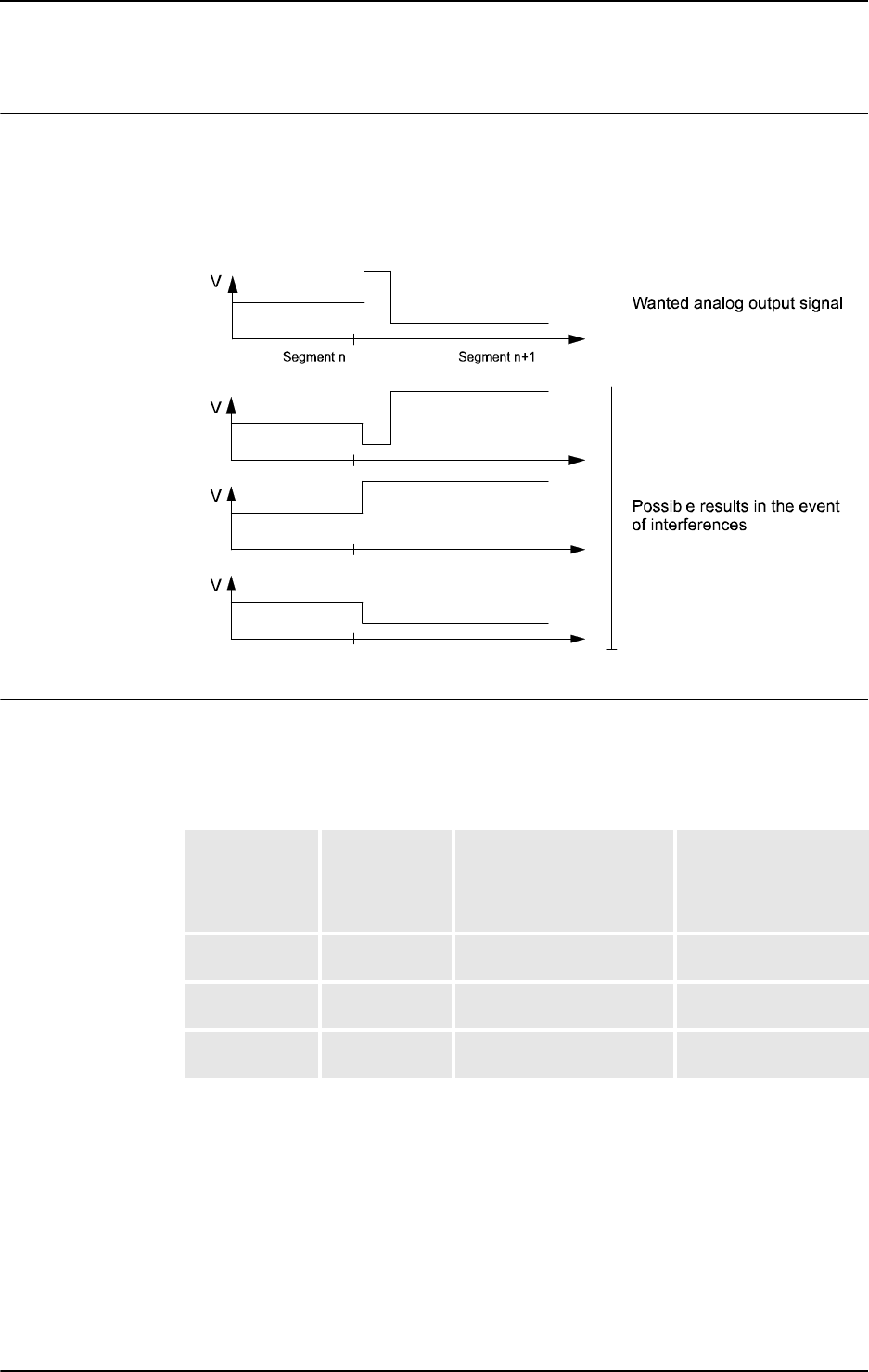
1 Instructions
1.215. TriggSpeed - Defines TCP speed proportional analog output with fixed position-time scale event
RobotWare - OS
6273HAC 16581-1 Revision: J
© Copyright 2004-2010 ABB. All rights reserved.
Error handling
Given two consecutive segments with
TriggL/TriggSpeed instructions. A negative value
in parameter
ScaleLag makes it possible to move the scale event from the first segment to
the beginning of the second segment. If the second segment scales at the beginning then there
is no control if the two scales interfere.
xx0500002334
Related system parameters
The system parameter Event Preset Time is used to delay the robot to make it possible to
activate/control the external equipment before the robot runs through the position.
The table below illustrates the recommendation for setup of system parameter Event Preset
Time, where typical Servo Lag is 0.040 s..
ScaleLag DipLag
Required Event Preset
Time to avoid runtime
execution error
Recommended
Event Preset Time to
obtain best accu-
racy
ScaleLag >
DipLag
Always DipLag,
if DipLag > Servo Lag
ScaleLag in s plus
0.090 s
ScaleLag <
DipLag
DipLag <
Servo Lag
- " - 0.090 s
- " - DipLag
>Servo Lag
- " - DipLag in s plus 0.030 s
Continued
Continues on next page

1 Instructions
1.215. TriggSpeed - Defines TCP speed proportional analog output with fixed position-time scale event
RobotWare - OS
3HAC 16581-1 Revision: J628
© Copyright 2004-2010 ABB. All rights reserved.
Syntax
TriggSpeed
[ TriggData ’:=’ ] < variable (VAR) of triggdata>´,’
[ Distance’ :=’ ] < expression (IN) of num>
[ ’\’ Start ] ´,’
[ ScaleLag’:=’ ] < expression (IN) of num> ´,’
[ AOp ’:=’] < variable (VAR) of signalao> ´,’
[ ScaleValue’ :=’ ] < expression (IN) of num>
[ ’\’ DipLag’ :=’ < expression (IN) of num> ]
[ ’\’ ErrDO’ :=’ < variable (VAR ) of signaldo> ]
[ ’\’ Inhib’ :=’ < persistent (PERS ) of bool >] ´;’
Related information
For information about See
Use of triggers TriggL - Linear robot movements with events on page
603
TriggC - Circular robot movement with events on page
570
TriggJ - Axis-wise robot movements with events on
page 597
Definition of other triggs TriggIO - Define a fixed position or time I/O event near
a stop point on page 592
TriggInt - Defines a position related interrupt on page
588
TriggEquip - Define a fixed position and time I/O event
on the path on page 582
Storage of triggs triggdata - Positioning events, trigg on page 1213
Configuration of Event preset time Technical reference manual - System parameters,
section Motion - Motion Planner - Event Preset Time
Continued

1 Instructions
1.216. TriggStopProc - Generate restart data for trigg signals at stop
RobotWare - OS
6293HAC 16581-1 Revision: J
© Copyright 2004-2010 ABB. All rights reserved.
1.216. TriggStopProc - Generate restart data for trigg signals at stop
Usage
The instruction
TriggStopProc creates an internal supervision process in the system for
zero setting of specified process signals and the generation of restart data in a specified
persistent variable at every program stop (
STOP) or emergency stop (QSTOP) in the system.
TriggStopProc and the data type restartdata are intended to be used for restart after
program stop (
STOP) or emergency stop (QSTOP) of own process instructions defined in
RAPID (
NOSTEPIN routines).
It is possible in a user defined
RESTART event routine to analyze the current restart data, step
backwards on the path with instruction
StepBwdPath, and activate suitable process signals
before the movement restarts.
This instruction can only be used in the main task
T_ROB1 or, if in a MultiMove system, in
any motion tasks.
Note for MultiMove system that only one
TriggStopProc support process with the
specified shadow signal name (argument
ShadowDO) can be active in the system at the same
time. It means that
TriggStopProc supervises program stop or emergency stop in the
program task where it was last executed.
Arguments
TriggStopProc RestartRef [\DO] [\GO1] [\GO2] [\GO3] [\GO4]
ShadowDO
RestartRef
Restart Reference
Data type:
restartdata
The persistent variable in which restart data will be available after every stop of program
execution.
[\DO1]
Digital Output 1
Data type:
signaldo
The signal variable for a digital process signal to be set to zero and supervised in restart data
when program execution is stopped.
[\GO1]
Group Output 1
Data type:
signalgo
The signal variable for a digital group process signal to be set to zero and supervised in restart
data when program execution is stopped.
[\GO2]
Group Output 2
Data type:
signalgo
The signal variable for a digital group process signal to be set to zero and supervised in restart
data when program execution is stopped.
Continues on next page

1 Instructions
1.216. TriggStopProc - Generate restart data for trigg signals at stop
RobotWare - OS
3HAC 16581-1 Revision: J630
© Copyright 2004-2010 ABB. All rights reserved.
[\GO3]
Group Output 3
Data type:
signalgo
The signal variable for a digital group process signal to be set to zero and supervised in restart
data when program execution is stopped.
[\GO4]
Group Output 4
Data type:
signalgo
The signal variable for a digital group process signal to be set to zero and supervised in restart
data when program execution is stopped.
At least one of the option parameters
D01, GO1 ... GO4 must be used.
ShadowDO
Shadow Digital Output
Data type:
signaldo
The signal variable for the digital signal, which must mirror whether or not the process is
active along the robot path.
This signal will not be set to zero by the process
TriggStopProc at STOP or QSTOP, but its
values will be mirrored in
restartdata.
Program execution
Setup and execution of TriggStopProc
TriggStopProc
must be called from both:
• the START event routine or in the unit part of the program (set PP to main, kill the
internal process for
TriggStopProc)
• the POWERON event routine (power off, kill the internal process for TriggStopProc)
The internal name of the process for
TriggStopProc is the same as the signal name in the
argument
ShadowDO. If TriggStopProc, with the same signal name in argument
ShadowDO, is executed twice from the same or another program task then only the last
executed
TriggStopProc will be active.
Execution of
TriggStopProc only starts the supervision of I/O signals at STOP and QSTOP.
Program stop STOP
The process TriggStopProc comprises the following steps:
• Wait until the robot stands still on the path.
• Store the current value (prevalue according to restartdata) of all used process
signals. Zero sets all used process signals except
ShadowDO.
• Do the following during the next time slot, about 500 ms: - If some process signals
change their value during this time: - Store the current value again (postvalue
according to
restatdata) - Set that signal to zero except ShadowDO - Count the
number of value transitions (flanks) of the signal
ShadowDO
• Update the specified persistent variable with restart data.
Continued
Continues on next page

1 Instructions
1.216. TriggStopProc - Generate restart data for trigg signals at stop
RobotWare - OS
6313HAC 16581-1 Revision: J
© Copyright 2004-2010 ABB. All rights reserved.
Emergency stop (QSTOP)
The process TriggStopProc comprises the following steps:
• Do the next step as soon as possible.
• Store the current value (prevalue according to restartdata) of all used process
signals. Set to zero all used process signals except
ShadowDO.
• Do the following during the next time slot, about 500 ms: - If some process signal
changes its value during this time: - Store its current value again (postvalue according
to
restatdata) - Set to zero that signal except ShadowDO - Count the number of
value transitions (flanks) of the signal
ShadowDO
• Update the specified persistent variable with restart data.
Critical area for process restart
Both the robot servo and the external equipment have some lags. All the instructions in the
Trigg family are designed so that all signals will be set at suitable places on the robot path,
independently of different lags in external equipment, to obtain process results that are as
good as possible. Because of this, the settings of I/O signals can be delayed between 0 - 80 ms
internally in the system after the robot stands still at program stop (
STOP) or after registration
of an emergency stop (
QSTOP). Because of this disadvantage for the restart functionality, both
the prevalue, postvalue, and the shadow flanks are introduced in restart data.
If this critical timeslot of 0 - 80 ms coincides with the following application process cases
then it is difficult to perform a good process restart:
• At the start of the application process
• At the end of the application process
• During a short application process
• During a short interrupt in the application process
Continued
Continues on next page
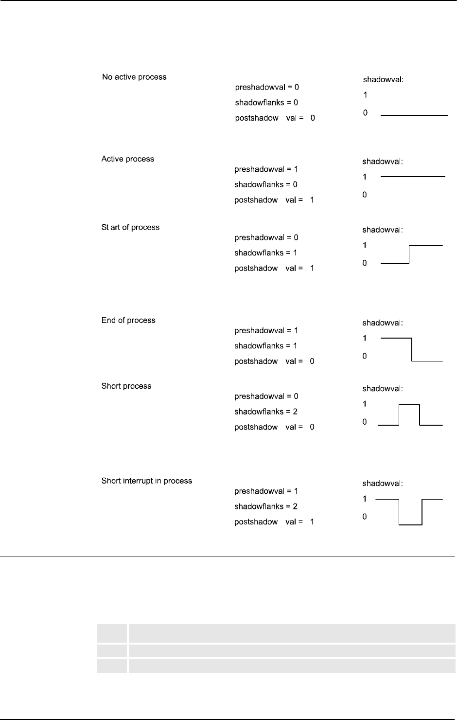
1 Instructions
1.216. TriggStopProc - Generate restart data for trigg signals at stop
RobotWare - OS
3HAC 16581-1 Revision: J632
© Copyright 2004-2010 ABB. All rights reserved.
The figure below illustrates process phases at STOP or QSTOP within critical time slot 0-80 ms
xx0500002326
Performing a restart
A restart of process instructions (
NOSTEPIN routines) along the robot path must be done in a
RESTART event routine.
The
RESTART event routine can consist of the following steps:
Action
1. After QSTOP the regain to path is done at program start.
2. Analyze the restart data from the latest STOP or QSTOP.
Continued
Continues on next page

1 Instructions
1.216. TriggStopProc - Generate restart data for trigg signals at stop
RobotWare - OS
6333HAC 16581-1 Revision: J
© Copyright 2004-2010 ABB. All rights reserved.
If waiting in any STOP or QSTOP event routine until the TriggStopProc process is ready
with e.g.
WaitUntil (myproc.restartstop=TRUE), \MaxTime:=2; , the user must
always reset the flag in the
RESTART event routine with e.g.
myproc.restartstop:=FALSE. After that the restart is ready.
Error handling
If there is no contact with the I/O unit, the system variable
ERRNO is set to ERR_NORUNUNIT
and the execution continues in the error handler.
Limitation
No support for restart of process instructions after a power failure.
Syntax
TriggStopProc
[ RestartRef ’:=’ ] < persistent (PERS) of restartdata>
[ ’\’ DO1’:=’ < variable (VAR) of signaldo>
[ ’\’ GO1’:=’ < variable (VAR) of signalgo> ]
[ ’\’ GO2’:=’ < variable (VAR) of signalgo> ]
[ ’\’ GO3’:=’ < variable (VAR) of signalgo> ]
[ ’\’ GO4’:=’ < variable (VAR) of signalgo> ] ’,’
[ ShadowDO’:=’ ] < variable (VAR) of signaldo> ’;’
Related information
3. Determine the strategy for process restart from the result of the analysis such as:
- Process active, do process restart
- Process inactive, do not process restart
- Do suitable actions depending on type of process application:
• Start of process
• End of process
• Short process
• Short interrupt in process
4. Step backwards on the path.
5. Continue the program results in movement restart.
Action
For information about See
Process instructions TriggL - Linear robot movements with events on
page 603
TriggC - Circular robot movement with events on
page 570
Restart data restartdata - Restart data for trigg signals on page
1167
Step backward on path StepBwdPath - Move backwards one step on path
on page 499
Continued

1 Instructions
1.217. TryInt - Test if data object is a valid integer
RobotWare - OS
3HAC 16581-1 Revision: J634
© Copyright 2004-2010 ABB. All rights reserved.
1.217. TryInt - Test if data object is a valid integer
Usage
TryInt is used to test if a given data object is a valid integer.
Basic examples
Basic examples of the instruction
TryInt are illustrated below.
Example 1
VAR num myint := 4;
...
TryInt myint;
The value of myint will be evaluated and since 4 is a valid integer, the program execution
continues.
Example 2
VAR dnum mydnum := 20000000;
...
TryInt mydnum;
The value of mydnum will be evaluated and since 20000000 is a valid dnum integer, the
program execution continues.
Example 3
VAR num myint := 5.2;
...
TryInt myint;
...
ERROR
IF ERRNO = ERR_INT_NOTVAL THEN
myint := Round(myint);
RETRY;
ENDIF
The value of myint will be evaluated and since 5.2 is not a valid integer, an error will be
raised. In the error handler,
myint will be rounded to 5 and the instruction TryInt is
executed one more time.
Arguments
TryInt DataObj | DataObj2
DataObj
Data Object
Data type:
num
The data object to test if it is a valid integer.
DataObj2
Data Object 2
Data type:
dnum
The data object to test if it is a valid integer.
Continues on next page

1 Instructions
1.217. TryInt - Test if data object is a valid integer
RobotWare - OS
6353HAC 16581-1 Revision: J
© Copyright 2004-2010 ABB. All rights reserved.
Program execution
The given data object is tested:
• If it is a valid integer, the execution continues with the next instruction.
• If it is not a valid integer, the execution continues in the error handler in an actual
procedure.
Error handling
If
DataObj contains a decimal value then the variable ERRNO will be set to
ERR_INT_NOTVAL.
If the value of
DataObj is larger or smaller then the integer value range of data type num then
the variable
ERRNO will be set to ERR_INT_MAXVAL.
If the value of
DataObj2 is larger or smaller then the integer value range of data type dnum
then the variable
ERRNO will be set to ERR_INT_MAXVAL.
These errors can be handled in the error handler.
Note that a value of
3.0 is evaluated as an integer, since.0 can be ignored.
Syntax
TryInt
[ DataObj ‘:=’ ] < expression (IN) of num>
| [ DataObj2 ‘:=’ ] < expression (IN) of dnum>’ ;’
Related information
For information about See
Data type num num - Numeric values on page 1146
Continued

1 Instructions
1.218. TRYNEXT - Jumps over an instruction which has caused an error
RobotWare-OS
3HAC 16581-1 Revision: J636
© Copyright 2004-2010 ABB. All rights reserved.
1.218. TRYNEXT - Jumps over an instruction which has caused an error
Usage
The TRYNEXT instruction is used to resume execution after an error, starting with the
instruction following the instruction that caused the error.
Basic examples
Basic examples of the instruction
TryNext are illustrated below.
Example 1
reg2 := reg3/reg4;
...
ERROR
IF ERRNO = ERR_DIVZERO THEN
reg2:=0;
TRYNEXT;
ENDIF
An attempt is made to divide reg3 by reg4. If reg4 is equal to 0 (division by zero) then a
jump is made to the error handler where
reg2 is assigned to 0. The TRYNEXT instruction is
then used to continue with the next instruction.
Program execution
Program execution continues with the instruction subsequent to the instruction that caused
the error.
Limitations
The instruction can only exist in a routine’s error handler.
Syntax
TRYNEXT’;’
Related information
For information about See
Error handlers Technical reference manual - RAPID overview,
section Basic Characteristics- Error Recovery

1 Instructions
1.219. TuneReset - Resetting servo tuning
RobotWare - OS
6373HAC 16581-1 Revision: J
© Copyright 2004-2010 ABB. All rights reserved.
1.219. TuneReset - Resetting servo tuning
Usage
TuneReset is used to reset the dynamic behavior of all robot axes and external mechanical
units to their normal values.
This instruction can only be used in the main task
T_ROB1 or, if in a MultiMove system, in
Motion tasks.
Basic examples
Basic examples of the instruction
TuneReset are illustrated below.
Example 1
TuneReset;
Resetting tuning values for all axes to 100%.
Program execution
The tuning values for all axes are reset to 100%.
The default servo tuning values for all axes are automatically set by executing instruction
TuneReset
• at a cold start-up.
• when a new program is loaded.
• when starting program execution from the beginning.
Syntax
TuneReset ’;’
Related information
For information about See
Tuning servos TuneServo - Tuning servos on page 638

1 Instructions
1.220. TuneServo - Tuning servos
RobotWare - OS
3HAC 16581-1 Revision: J638
© Copyright 2004-2010 ABB. All rights reserved.
1.220. TuneServo - Tuning servos
Usage
TuneServo is used to tune the dynamic behavior of separate axes on the robot. It is not
necessary to use
TuneServo under normal circumstances, but sometimes tuning can be
optimized depending on the robot configuration and the load characteristics. For external
axes
TuneServo can be used for load adaptation.
Avoid doing
TuneServo commands at the same time that the robot is moving. It can result
in momentary high CPU loads causing error indication and stops.
Note! To obtain optimal tuning it is essential that the correct load data is used. Check this
before using
TuneServo.
Generally, optimal tuning values often differ between different robots. Optimal tuning may
also change with time.
This instruction can only be used in the main task
T_ROB1 or, if in a MultiMove system, in
Motion tasks.
WARNING!
Incorrect use of the
TuneServo can cause oscillating movements or torques that can damage
the robot. You must bear this in mind and be careful when using the
TuneServo.
Improving path accuracy
For robots running at lower speeds, TuneServo can be used to improve the path accuracy by:
• Tuning TUNE_KV and TUNE_TI (see the tune types description below).
• Tuning friction compensation parameters (see below).
These two methods can be combined.
Other possibilities to improve the path accuracy:
• Decreasing path resolution can improve the path. Note: a value of path resolution
which is too low will cause CPU load problems.
• The accuracy of straight lines can be improved by decreasing acceleration using
AccSet. Example: AccSet 20, 10.
Continues on next page

1 Instructions
1.220. TuneServo - Tuning servos
RobotWare - OS
6393HAC 16581-1 Revision: J
© Copyright 2004-2010 ABB. All rights reserved.
Description
Reduce overshoots - TUNE_DF
TUNE_DF
is used for reducing overshoots or oscillations along the path.
There is always an optimum tuning value that can vary depending on position and movement
length. This optimum value can be found by changing the tuning in small steps (1 - 2%) on
the axes that are involved in this unwanted behavior. Normally the optimal tuning will be
found in the range 70% - 130%. Too low or too high tuning values have a negative effect and
will impair movements considerably.
When the tuning value at the start point of a long movement differs considerably from the
tuning value at the end point, it can be advantageous in some cases to use an intermediate
point with a corner zone to define where the tuning value will change.
Some examples of the use of
TuneServo to optimize tuning follow below:
• IRB 6400, in a press service application (extended and flexible load), axes 4 - 6:
Reduce the tuning value for the current wrist axis until the movement is acceptable. A
change in the movement will not be noticeable until the optimum value is approached.
A low value will impair the movement considerably. Typical tuning value is 25%.
• IRB 6400, upper parts of working area. Axis 1 can often be optimized with a tuning
value of 85% - 95%.
• IRB 6400, short movement (< 80 mm). Axis 1 can often be optimized with a tuning
value of 94% - 98%.
• IRB 2400, with track motion. In some cases axes 2 - 3 can be optimized with a tuning
value of 110% - 130%. The movement along the track can require a different tuning
value compared with movement at right angles to the track.
• Overshoots and oscillations can be reduced by decreasing the acceleration or the
acceleration ramp (
AccSet), which will however increase the cycle time. This is an
alternative method to the use of
TuneServo.
Reduce overshoots - TUNE_DG
TUNE_DG
can reduce overshoots on rare occasions. Normally it should not be used.
TUNE_DF should always be tried first in cases of overshooting.
Tuning of
TUNE_DG can be performed with large steps in tune value (e.g. 50%, 100%, 200%,
400%).
Never use
TUNE_DG when the robot is moving.
Continued
Continues on next page

1 Instructions
1.220. TuneServo - Tuning servos
RobotWare - OS
3HAC 16581-1 Revision: J640
© Copyright 2004-2010 ABB. All rights reserved.
Reduces vibrations with heavy loads - TUNE_DH
TUNE_DH
can be used for reducing vibrations and overshooting (e.g. large flexible load).
Tune value must always be lower than 100.
TUNE_DH increases path deviation and normally
also increases cycle time.
Example:
• IRB6400 with large flexible loads which vibrates when the robot has stopped. Use
TUNE_DH with tune value 15.
TUNE_DH should only be executed for one axis. All axes in the same mechanical unit
automatically get the same
TuneValue.
Never use
TUNE_DH when the robot is moving.
Reduce path errors - TUNE_DI
TUNE_DI
can be used for reducing path deviation at high speeds.
A tune value in the range 50 - 80 is recommended for reducing path deviation. Overshooting
can increase (lower tune value means larger overshoot).
A higher tune value than 100 can reduce overshooting (but increases path deviation at high
speed).
TUNE_DI should only be executed for one axis. All axes in the same mechanical unit
automatically get the same
TuneValue.
Only for ABB internal use - TUNE_DK, TUNE_DL
-
WARNING!
Only for ABB internal use. Do not use these tune types. Incorrect use can cause oscillating
movements or torques that can damage the robot.
Tuning external axes - TUNE_KP, TUNE_KV, TUNE_TI
These tune types affect position control gain (kp), speed control gain (kv), and speed control
integration time (ti) for external axes. These are used for adapting external axes to different
load inertias. Basic tuning of external axes can also be simplified by using these tune types.
Tuning robot axes - TUNE_KP, TUNE_KV, TUNE_TI
For robot axes, these tune types have another significance and can be used for reducing path
errors at low speeds (< 500 mm/s).
Recommended values:
TUNE_KV 100 - 180%, TUNE_TI 50 - 100%. TUNE_KP should not be
used for robot axes. Values of
TUNE_KV/TUNE_TI which are too high or too low will cause
vibrations or oscillations. Be careful if trying to exceed these recommended values. Make
changes in small steps and avoid oscillating motors.
Always tune one axis at a time. Change the tuning values in small steps. Try to improve the
path where this specific axis changes its direction of movement or where it accelerates or
decelerates.
Never use these tune types at high speeds or when the required path accuracy is fulfilled.
Continued
Continues on next page
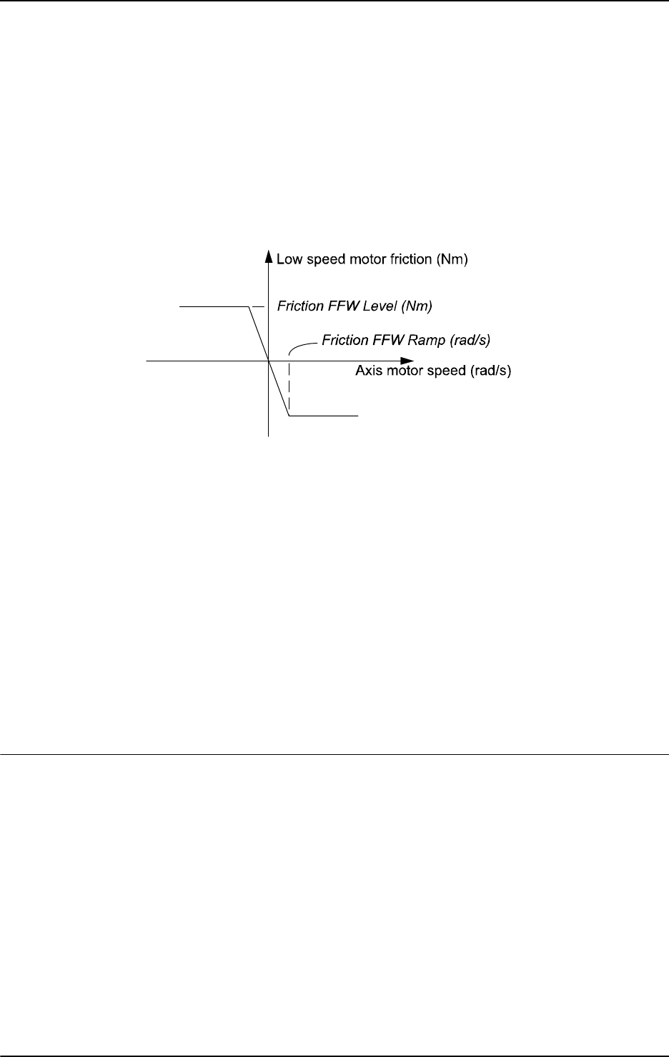
1 Instructions
1.220. TuneServo - Tuning servos
RobotWare - OS
6413HAC 16581-1 Revision: J
© Copyright 2004-2010 ABB. All rights reserved.
Friction compensation - TUNE_FRIC_LEV, TUNE_FRIC_RAMP
These tune types can be used to reduce robot path errors caused by friction and backlash at
low speeds (10 - 200 mm/s). These path errors appear when a robot axis changes direction of
movement. Activate friction compensation for an axis by setting the system parameter
Motion/Control Parameters/Friction FFW On to Yes.
The friction model is a constant level with opposite sign of the axis speed direction. Friction
FFW Level (Nm) is the absolute friction level at (low) speeds and is greater than Friction
FFW Ramp (rad/s). See the figure below, which shows a friction model.
xx0500002188
TUNE_FRIC_LEV overrides the value of the system parameter Friction FFW Level.
Tuning Friction FFW Level (using
TUNE_FRIC_LEV) for each robot axis can improve the
robot’s path accuracy considerably in the speed range 20 - 100 mm/s. For larger robots
(especially the IRB6400 family) the effect will, however, be minimal as other sources of
tracking errors dominate these robots.
TUNE_FRIC_RAMP overrides the value of the system parameter Friction FFW Ramp. In most
cases there is no need to tune the Friction FFW Ramp. The default setting will be appropriate.
Tune one axis at a time. Change the tuning value in small steps and find the level that
minimizes the robot path error at positions on the path where this specific axis changes
direction of movement. Repeat the same procedure for the next axis etc.
The final tuning values can be transferred to the system parameters. Example:
Friction FFW Level = 1. Final tune value (
TUNE_FRIC_LEV) = 150%.
Set Friction FFW Level = 1.5 and tune value = 100% (default value) which is equivalent.
Arguments
TuneServo MecUnit Axis TuneValue [\Type]
MecUnit
Mechanical Unit
Data type:
mecunit
The name of the mechanical unit.
Axis
Data type: num
The number of the current axis for the mechanical unit (1 - 6).
Continued
Continues on next page

1 Instructions
1.220. TuneServo - Tuning servos
RobotWare - OS
3HAC 16581-1 Revision: J642
© Copyright 2004-2010 ABB. All rights reserved.
TuneValue
Data type: num
Tuning value in percent (1 - 500). 100% is the normal value.
[ \Type ]
Data type: tunetype
Type of servo tuning. Available types are TUNE_DF, TUNE_KP, TUNE_KV, TUNE_TI,
TUNE_FRIC_LEV, TUNE_FRIC_RAMP, TUNE_DG, TUNE_DH, TUNE_DI
. Type TUNE_DK
and
TUNE_DL only for ABB internal use.
This argument can be omitted when using tuning type
TUNE_DF.
Basic examples
Basic examples of the instruction
TuneServo are illustrated below.
Example 1
TuneServo MHA160R1, 1, 110 \Type:= TUNE_KP;
Activating of tuning type TUNE_KP with the tuning value 110% on axis 1 in the mechanical
unit
MHA160R1.
Program execution
The specified tuning type and tuning value are activated for the specified axis. This value is
applicable for all movements until a new value is programmed for the current axis, or until
the tuning types and values for all axes are reset using the instruction
TuneReset.
The default servo tuning values for all axes are automatically set by executing instruction
TuneReset
• at a cold start-up.
• when a new program is loaded.
• when starting program execution from the beginning.
Limitations
Any active servo tuning are always set to default values at power fail.
This limitation can be handled in the user program at restart after power failure.
Syntax
TuneServo
[MecUnit ’:=’ ] < variable (VAR) of mecunit>’ ,’
[Axis ’:=’ ] < expression (IN) of num> ’,’
[TuneValue’ :=’ ] < expression (IN) of num>
[’\’ Type’ :=’ <expression (IN) of tunetype>]’;’
Continued
Continues on next page

1 Instructions
1.220. TuneServo - Tuning servos
RobotWare - OS
6433HAC 16581-1 Revision: J
© Copyright 2004-2010 ABB. All rights reserved.
Related information
For information about See
Other motion settings Technical reference manual - RAPID overview, section
RAPID summary - Motion settings
Types of servo tuning tunetype - Servo tune type on page 1222
Reset of all servo tunings TuneReset - Resetting servo tuning on page 637
Tuning of external axes Application manual - Additional axes and stand alone
controller
Friction compensation Technical reference manual - System parameters, section
Motion - Friction Compensation
Continued

1 Instructions
1.221. UIMsgBox - User Message Dialog Box type basic
RobotWare - OS
3HAC 16581-1 Revision: J644
© Copyright 2004-2010 ABB. All rights reserved.
1.221. UIMsgBox - User Message Dialog Box type basic
Usage
UIMsgBox (User Interaction Message Box) is used to communicate with the user of the robot
system on available user device, such as the FlexPendant. A message is written to the
operator, who answers by selecting a button. The user selection is then transferred back to the
program.
Basic examples
Basic examples of the instruction
UIMsgBox are illustrated below.
See also More examples on page 648.
Example 1
UIMsgBox Continue the program ?;
The message "Continue the program ?" is displayed. The program proceeds when the
user presses the default button OK.
Example 2
VAR btnres answer;
...
UIMsgBox
\Header:="UIMsgBox Header",
"Message Line 1"
\MsgLine2:="Message Line 2"
\MsgLine3:="Message Line 3"
\MsgLine4:="Message Line 4"
\MsgLine5:="Message Line 5"
\Buttons:=btnOKCancel
\Icon:=iconInfo
\Result:=answer;
IF answer = resOK my_proc;
Continues on next page
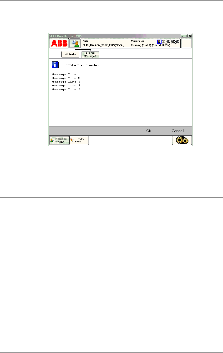
1 Instructions
1.221. UIMsgBox - User Message Dialog Box type basic
RobotWare - OS
6453HAC 16581-1 Revision: J
© Copyright 2004-2010 ABB. All rights reserved.
xx0500002432
Above message box with icon, header, message line 1 to 5, and push buttons is written on the
FlexPendant display. Program execution waits until OK or Cancel is pressed. In other words,
answer will be assigned 1 (OK) or 5 (Cancel) depending on which of the buttons is pressed.
If answer is OK then
my_proc will be called.
Note that Message Line 1 ... Message Line 5 are displayed on separate lines 1 to 5 (the switch
\Wrap is not used).
Arguments
UIMsgBox [\Header] MsgLine1 [\MsgLine2] [\MsgLine3] [\MsgLine4]
[\MsgLine5] [\Wrap] [\Buttons] [\Icon] [\Image] [\Result]
[\MaxTime] [\DIBreak] [\DOBreak] [\BreakFlag]
[\Header]
Data type: string
Header text to be written at the top of the message box. Max. 40 characters.
MsgLine1
Message Line 1
Data type:
string
Text line 1 to be written on the display. Max. 55 characters.
[\MsgLine2]
Message Line 2
Data type:
string
Additional text line 2 to be written on the display. Max. 55 characters.
[\MsgLine3]
Message Line 3
Data type:
string
Additional text line 3 to be written on the display. Max. 55 characters.
Continued
Continues on next page

1 Instructions
1.221. UIMsgBox - User Message Dialog Box type basic
RobotWare - OS
3HAC 16581-1 Revision: J646
© Copyright 2004-2010 ABB. All rights reserved.
[\MsgLine4]
Message Line 4
Data type:
string
Additional text line 4 to be written on the display. Max. 55 characters.
[\MsgLine5]
Message Line 5
Data type:
string
Additional text line 5 to be written on the display. Max. 55 characters.
[\Wrap]
Data type: switch
If selected, all the strings
MsgLine1 ... MsgLine5 will be concatenated to one string with
a single space between each individual string and spread out on as few lines as possible.
Default, each message string MsgLine1 ... MsgLine5 will be on separate lines on the display.
[\Buttons]
Data type: buttondata
Defines the push buttons to be displayed. Only one of the predefined buttons combination of
type
buttondata can be used. See Predefined data on page 648.
Default, the system displays the OK button. (
\Buttons:=btn OK).
[\Icon]
Data type: icondata
Defines the icon to be displayed. Only one of the predefined icons of type icondata can be
used. See Predefined data on page 648.
Default no icon.
[\Image]
Data type: string
The name of the image that should be used. To launch your own images, the images have to
be placed in the
HOME: directory in the active system or directly in the active system.
The recommendation is to place the files in the
HOME: directory so that they are saved if a
Backup and Restore is done.
A warmstart is required and then the FlexPendant will load the images.
A demand on the system is that the RobotWare option FlexPendant Interface is used.
The image that will be showed can have the width of 185 pixels and the height of 300 pixels.
If the image is bigger, only 185 * 300 pixels of the image will be shown starting at the top left
of the image.
No exact value can be specified on the size that an image can have or the amount of images
that can be loaded to the FlexPendant. It depends on the size of other files loaded to the
FlexPendant. The program execution will just continue if an image is used that has not been
loaded to the FlexPendant.
Continued
Continues on next page

1 Instructions
1.221. UIMsgBox - User Message Dialog Box type basic
RobotWare - OS
6473HAC 16581-1 Revision: J
© Copyright 2004-2010 ABB. All rights reserved.
[\Result]
Data type: btnres
The variable for which, depending on which button is pressed, the numeric value 0..7 is
returned. Only one of the predefined constants of type
btnres can be used to test the user
selection. See Predefined data on page 648.
If any type of system break such as
\MaxTime, \DIBreak, or \DOBreak or if
\Buttons:=btnNone, resUnkwn equal to 0 is returned.
[\MaxTime]
Data type: num
The maximum amount of time in seconds that program execution waits. If no button is
selected within this time then the program continues to execute in the error handler unless the
BreakFlag is used (see below). The constant ERR_TP_MAXTIME can be used to test whether
or not the maximum time has elapsed.
[\DIBreak]
Digital Input Break
Data type:
signaldi
The digital input signal that may interrupt the operator dialog. If no button is selected when
the signal is set to 1 (or is already 1), the program continues to execute in the error handler,
unless the
BreakFlag is used (see below). The constant ERR_TP_DIBREAK can be used to
test whether or not this has occurred.
[\DOBreak]
Digital Output Break
Data type:
signaldo
The digital output signal that may interrupt the operator dialog. If no button is selected when
the signal is set to 1 (or is already 1) then the program continues to execute in the error handler
unless the
BreakFlag is used (see below). The constant ERR_TP_DOBREAK can be used to
test whether or not this has occurred.
[\BreakFlag]
Data type: errnum
A variable (before used it is set to 0 by the system) that will hold the error code if \MaxTime,
\DIBreak, or \DOBreak is used. The constants ERR_TP_MAXTIME, ERR_TP_DIBREAK, and
ERR_TP_DOBREAK can be used to select the reason. If this optional variable is omitted then
the error handler will be executed.
Program execution
The message box with icon, header, message lines, image, and buttons are displayed
according to the programmed arguments. Program execution waits until the user selects one
button or the message box is interrupted by time-out or signal action. The user selection and
interrupt reason are transferred back to the program.
New message box on TRAP level takes the focus from the message box on the basic level.
Continued
Continues on next page

1 Instructions
1.221. UIMsgBox - User Message Dialog Box type basic
RobotWare - OS
3HAC 16581-1 Revision: J648
© Copyright 2004-2010 ABB. All rights reserved.
Predefined data
!Icons:
CONST icondata iconNone := 0;
CONST icondata iconInfo := 1;
CONST icondata iconWarning := 2;
CONST icondata iconError := 3;
!Buttons:
CONST buttondata btnNone := -1;
CONST buttondata btnOK := 0;
CONST buttondata btnAbrtRtryIgn := 1;
CONST buttondata btnOKCancel := 2;
CONST buttondata btnRetryCancel := 3;
CONST buttondata btnYesNo := 4;
CONST buttondata btnYesNoCancel := 5;
!Results:
CONST btnres resUnkwn := 0;
CONST btnres resOK := 1;
CONST btnres resAbort := 2;
CONST btnres resRetry := 3;
CONST btnres resIgnore := 4;
CONST btnres resCancel := 5;
CONST btnres resYes := 6;
CONST btnres resNo := 7;
More examples
More examples of how to use the instruction
UIMsgBox are illustrated below.
Example 1
VAR errnum err_var;
...
UIMsgBox \Header:= "Example 1", "Waiting for a break condition..."
\Buttons:=btnNone \Icon:=iconInfo \MaxTime:=60 \DIBreak:=di5
\BreakFlag:=err_var;
TEST err_var
CASE ERR_TP_MAXTIME:
! Time out break, max time 60 seconds has elapsed
CASE ERR_TP_DIBREAK:
! Input signal break, signal di5 has been set to 1
DEFAULT:
! Not such case defined
ENDTEST
The message box is displayed until a break condition has become true. The operator can not
answer or remove the message box because
btnNone is set for the argument \Buttons. The
message box is removed when
di5 is set to 1 or at time out (after 60 seconds).
Continued
Continues on next page

1 Instructions
1.221. UIMsgBox - User Message Dialog Box type basic
RobotWare - OS
6493HAC 16581-1 Revision: J
© Copyright 2004-2010 ABB. All rights reserved.
Error handling
If parameter
\BreakFlag is not used then these situations can then be dealt with by the error
handler:
• If there is a time-out (parameter \MaxTime) before an input from the operator then the
system variable
ERRNO is set to ERR_TP_MAXTIME and the execution continues in the
error handler.
• If digital input is set (parameter \DIBreak) before an input from the operator then the
system variable
ERRNO is set to ERR_TP_DIBREAK and the execution continues in the
error handler.
• If a digital output is set (parameter \DOBreak) before an input from the operator then
the system variable
ERRNO is set to ERR_TP_DOBREAK and the execution continues in
the error handler.
This situation can only be dealt with by the error handler:
• If there is no client, e.g. a FlexPendant, to take care of the instruction then the system
variable
ERRNO is set to ERR_TP_NO_CLIENT and the execution continues in the error
handler.
Limitations
Avoid using too small of a value for the time-out parameter
\MaxTime when UIMsgBox is
frequently executed, like in a loop. It can result in an unpredictable behavior of the system
performance, like slow response of the FlexPendant.
Syntax
UIMsgBox
[´\´Header´:=´ <expression (IN) of string>´,´]
[MsgLine1´:=´] <expression (IN) of string>
[´\´MsgLine2´:=´<expression (IN) of string>]
[´\´MsgLine3´:=´<expression (IN) of string>]
[´\´MsgLine4´:=´<expression (IN) of string>]
[´\´MsgLine5´:=´<expression (IN) of string>]
[´\´Wrap]
[´\´Buttons´:=´ <expression (IN) of buttondata>]
[´\´Icon´:=´ <expression (IN) of icondata>]
[‘\’Image´:=´<expression (IN) of string>]
[´\´Result´:=´< var or pers (INOUT) of btnres>]
[´\´MaxTime´:=´ <expression (IN) of num>]
[´\´DIBreak´:=´ <variable (VAR) of signaldi>]
[´\´DOBreak´:=´ <variable (VAR) of signaldo>]
[´\´BreakFlag´:=´ <var or pers (INOUT) of errnum>]´;´
Continued
Continues on next page

1 Instructions
1.221. UIMsgBox - User Message Dialog Box type basic
RobotWare - OS
3HAC 16581-1 Revision: J650
© Copyright 2004-2010 ABB. All rights reserved.
Related information
For information about See
Icon display data icondata - Icon display data on page 1121
Push button data buttondata - Push button data on page 1089
Push button result data btnres - Push button result data on page 1086
User Interaction Message Box type
advanced
UIMessageBox - User Message Box type
advanced on page 1057
User Interaction Number Entry UINumEntry - User Number Entry on page
1064
User Interaction Number Tune UINumTune - User Number Tune on page
1070
User Interaction Alpha Entry UIAlphaEntry - User Alpha Entry on page 1032
User Interaction List View UIListView - User List View on page 1050
System connected to FlexPendant etc. UIClientExist - Exist User Client on page 1037
FlexPendant interface Product Specification - Controller Software
IRC5, RobotWare 5.0, section Communication
- FlexPendant Interface
Clean up the Operator window TPErase - Erases text printed on the
FlexPendant on page 556
Continued

1 Instructions
1.222. UIShow - User Interface show
6513HAC 16581-1 Revision: J
© Copyright 2004-2010 ABB. All rights reserved.
1.222. UIShow - User Interface show
Usage
UIShow (User Interface Show) is used to communicate with the user of the robot system on
the available User Device such as the FlexPendant. With
UIShow both individually written
applications and standard applications can be launched from a RAPID program.
Basic examples
Basic examples of the instruction
UIShow are illustrated below.
Example 1 and example 2 only works if the files
TpsViewMyAppl.dll and
TpsViewMyAppl.gtpu.dll is present in the HOME: directory, and a warmstart has been
performed.
Example 1
CONST string Name:="TpsViewMyAppl.gtpu.dll";
CONST string Type:="ABB.Robotics.SDK.Views.TpsViewMyAppl";
CONST string Cmd1:="Init data string passed to the view";
CONST string Cmd2:="New init data string passed to the view";
PERS uishownum myinstance:=0;
VAR num mystatus:=0;
...
! Launch one view of my application MyAppl
UIShow Name, Type \InitCmd:=Cmd1 \InstanceID:=myinstance
\Status:=mystatus;
! Update the view with new init command
UIShow Name, Type \InitCmd:=Cmd2 \InstanceID:=myinstance
\Status:=mystatus;
The code above will launch the view TpsViewMyAppl with init command Cmd1, and then
update the view with
Cmd2.
Example 2
CONST string Name:="TpsViewMyAppl.gtpu.dll";
CONST string Type:="ABB.Robotics.SDK.Views.TpsViewMyAppl";
CONST string Cmd1:="Init data string passed to the view";
CONST string Cmd2:="New init data string passed to the view";
PERS uishownum myinstance:=0;
VAR num mystatus:=0;
...
! Launch one view of my application MyAppl
UIShow Name, Type \InitCmd:=Cmd1 \Status:=mystatus;
! Launch another view of the application MyAppl
UIShow Name, Type \InitCmd:=Cmd2 \InstanceID:=myinstance
\Status:=mystatus;
The code above will launch the view TpsViewMyAppl with init command Cmd1. Then it
launches another view with init command
Cmd2.
Continues on next page

1 Instructions
1.222. UIShow - User Interface show
3HAC 16581-1 Revision: J652
© Copyright 2004-2010 ABB. All rights reserved.
Example 3
CONST string Name:="tpsviewbackupandrestore.dll";
CONST string
Type:="ABB.Robotics.Tps.Views.TpsViewBackupAndRestore";
VAR num mystatus:=0;
...
UIShow Name, Type \Status:=mystatus;
Launch standard application Backup and Restore.
Arguments
UIShow AssemblyName TypeName [\InitCmd] [\InstanceId] [\Status]
[\NoCloseBtn]
AssemblyName
Data type: string
The name of the assembly that contains the view.
TypeName
Data type: string
This is the name of the view (the type to create). This is the fully qualified name of the type,
i.e. its namespace is included.
[\InitCmd]
Init Command
Data type:
string
A init data string passed to the view.
[\InstanceId]
Data type: uishownum
A parameter that represents a token used to identify a view. If a view is shown after the call
to
UIShow then a value that identifies the view is passed back. This token can then be used
in other calls to
UIShow to activate an already running view. If the value identifies an existing
(running) view then the view will be activated. If it does not exist then a new instance will be
created. This means that this parameter can be used to determine if a new instance will be
launched or not. If its value identifies an already started view then this view will be activated
regardless of the values of all other parameters. A recommendation is to use an unique
InstanceId variable for each new application that is going to be launched with the UIShow
instruction.
The parameter must be a persistent variable and the reason for this is that this variable should
keep its value, even if the program pointer is moved to main. If executing the same
UIShow
as earlier and using the same variable then the same view will be activated if it is still open.
If the view has been closed then a new view will be launched.
Continued
Continues on next page

1 Instructions
1.222. UIShow - User Interface show
6533HAC 16581-1 Revision: J
© Copyright 2004-2010 ABB. All rights reserved.
[\Status]
Data type: num
Status
indicates if the operation was successful or not. Note that if this option is used then
the RAPID execution will be waiting until the instruction is completed, i.e. the view is
launched.
This optional parameter is primary used for debugging purpose. (See Error handling)
[\NoCloseBtn]
No Close Button
Data type:
switch
NoCloseBtn
disables the close button of the view.
Program execution
The
UIShow instruction is used to launch individual applications on the FlexPendant. To
launch individual applications, the assemblies have to be placed in the
HOME: directory in the
active system, or directly in the active system, or in an additional option. The
recommendation is to place the files in the
HOME: directory so that they are saved if a Backup
and Restore is done. A warmstart is required and then the FlexPendant loads the new
assemblies. A demand on the system is that the RobotWare option FlexPendant Interface is
used.
It is also possible to launch standard applications such as Backup and Restore. Then there is
no demand to have the RobotWare option FlexPendant Interface.
If using the parameter
\Status then the program execution will wait until the application is
launched. If errors in the application are not handled then it is only the result of the launch
that is supervised. Without the
\Status parameter, the FlexPendant is ordered to launch the
application but there is no check to determine if it is possible to launch it or not.
Status Description
0 OK
-1 No space left on the FlexPendant for the new view. Maximum 6
views can be open at the same time on the FlexPendant.
-2 Assembly could not be found, does not exist
-3 File was found, but could not be loaded
-4 Assembly exist, but no new instance could be created
-5 The typename is invalid for this assembly
-6 InstanceID does not match assembly to load
Continued
Continues on next page

1 Instructions
1.222. UIShow - User Interface show
3HAC 16581-1 Revision: J654
© Copyright 2004-2010 ABB. All rights reserved.
Error handling
If there is no client, e.g. a FlexPendant, to take care of the instruction then the system variable
ERRNO is set to ERR_TP_NO_CLIENT and the execution continues in the error handler.
If parameter
\Status is used then these situations can then be dealt with by the error handler:
• If there is no space left on the FlexPendant for the assembly then the system variable
ERRNO is set to ERR_UISHOW_FULL and the execution continues in the error handler.
The FlexPendant can have 6 views open at the same time.
• If something else goes wrong when trying to launch a view then the system variable
ERRNO is set to ERR_UISHOW_FATAL, and the execution continues in the error handler.
Limitations
When using
UIShow instruction to launch individual applications then it is a demand that the
system is equipped with the option FlexPendant Interface.
Applications that have been launched with the
UIShow instruction do not survive power fail
situations.
POWER ON event routine can be used to setup the application again.
Syntax
UIShow
[AssemblyName ´:=´] < expression (IN) of string >’,’
[TypeName ´:=´] < expression (IN) of string >’,’
[’\’InitCmd’ :=’ < expression (IN) of string> ]
[’\’InstanceId ’:=’ < persistent (PERS) of uishownum> ]
[’\’Status ’:=’ < variable (VAR) of num> ]
[’\’NoCloseBtn ]’;’
Related information
For information about See
FlexPendant nterface Product Specification - Controller Software
IRC5, RobotWare 5.0, section Communication
- FlexPendant Interface
Building individual applications for the
FlexPendant
Application manual - Robot Application Builder
uishownum uishownum - Instance ID for UIShow on page
1223
Clean up the Operator window TPErase - Erases text printed on the
FlexPendant on page 556
Continued

1 Instructions
1.223. UnLoad - UnLoad a program module during execution
RobotWare - OS
6553HAC 16581-1 Revision: J
© Copyright 2004-2010 ABB. All rights reserved.
1.223. UnLoad - UnLoad a program module during execution
Usage
UnLoad is used to unload a program module from the program memory during execution.
The program module must have previously been loaded into the program memory using the
instructions
Load or StartLoad - WaitLoad.
Basic examples
Basic examples of the instruction
UnLoad are illustrated below.
See also More examples below.
Example 1
UnLoad diskhome \File:="PART_A.MOD";
UnLoad
the program module PART_A.MOD from the program memory that was previously
loaded into the program memory with
Load. (See instruction Load). diskhome is a
predefined string constant "HOME:".
Arguments
UnLoad [\ErrIfChanged] | [\Save] FilePath [\File]
[\ErrIfChanged]
Data type: switch
If this argument is used, and the module has been changed since it was loaded into the system,
then the instruction will generate the error recovery code
ERR_NOTSAVED.
[\Save]
Data type: switch
If this argument is used then the program module is saved before the unloading starts. The
program module will be saved at the original place specified in the
Load or StartLoad
instruction.
FilePath
Data type: string
The file path and the file name to the file that will be unloaded from the program memory.
The file path and the file name must be the same as in the previously executed
Load or
StartLoad instruction. The file name shall be excluded when the argument \File is used.
[\File]
Data type: string
When the file name is excluded in the argument FilePath, then it must be defined with this
argument. The file name must be the same as in the previously executed
Load or StartLoad
instruction.
Continues on next page

1 Instructions
1.223. UnLoad - UnLoad a program module during execution
RobotWare - OS
3HAC 16581-1 Revision: J656
© Copyright 2004-2010 ABB. All rights reserved.
Program execution
To be able to execute an
UnLoad instruction in the program, a Load or StartLoad -
WaitLoad
instruction with the same file path and name must have been executed earlier in
the program.
The program execution waits for the program module to finish unloading before the
execution proceeds with the next instruction.
After that the program module is unloaded, and the rest of the program modules will be
linked.
For more information see the instructions
Load or StartLoad-Waitload.
More examples
More examples of how to use the instruction
UnLoad are illustrated below.
Example 1
UnLoad "HOME:/DOORDIR/DOOR1.MOD";
UnLoad
the program module DOOR1.MOD from the program memory that was previously
loaded into the program memory.
Example 2
UnLoad "HOME:" \File:="DOORDIR/DOOR1.MOD";
Same as in example 1 above but another syntax.
Example 3
Unload \Save, "HOME:" \File:="DOORDIR/DOOR1.MOD";
Same as in examples 1 and 2 above but saves the program module before unloading.
Limitations
It is not allowed to unload a program module that is executing (program pointer in the
module).
TRAP routines, system I/O events, and other program tasks cannot execute during the
unloading.
Avoid ongoing robot movements during the unloading.
Program stop during execution of
UnLoad instruction can result in guard stop with motors off
and error message "20025 Stop order timeout" on the FlexPendant.
Error handling
If the file in the
UnLoad instruction cannot be unloaded because of ongoing execution within
the module or wrong path (module not loaded with
Load or StartLoad) then the system
variable
ERRNO is set to ERR_UNLOAD.
If the argument
\ErrIfChanged is used and the module has been changed then the execution
of this routine will set the system variable
ERRNO to ERR_NOTSAVED.
Those errors can then be handled in the error handler.
Continued
Continues on next page

1 Instructions
1.223. UnLoad - UnLoad a program module during execution
RobotWare - OS
6573HAC 16581-1 Revision: J
© Copyright 2004-2010 ABB. All rights reserved.
Syntax
UnLoad
[’\’ErrIfChanged ’,’] | [’\’Save ’,’]
[FilePath’:=’]<expression (IN) of string>
[’\’File’:=’ <expression (IN) of string>]’;’
Related information
For information about See
Check program references CheckProgRef - Check program references on page 37
Load a program module Load - Load a program module during execution on page 208
StartLoad - Load a program module during execution on page
482
WaitLoad - Connect the loaded module to the task on page
682
Continued

1 Instructions
1.224. UnpackRawBytes - Unpack data from rawbytes data
RobotWare - OS
3HAC 16581-1 Revision: J658
© Copyright 2004-2010 ABB. All rights reserved.
1.224. UnpackRawBytes - Unpack data from rawbytes data
Usage
UnpackRawBytes is used to unpack the contents of a container of type rawbytes to
variables of type
byte, num, dnum or string.
Basic examples
Basic examples of the instruction
UnpackRawBytes are illustrated below.
Example 1
VAR iodev io_device;
VAR rawbytes raw_data_out;
VAR rawbytes raw_data_in;
VAR num integer;
VAR dnum bigInt;
VAR num float;
VAR string string1;
VAR byte byte1;
VAR byte data1;
! Data packed in raw_data_out according to the protocol
...
Open "chan1:", io_device\Bin;
WriteRawBytes io_device, raw_data_out;
ReadRawBytes io_device, raw_data_in\Time := 1;
Close io_device;
According to the protocol that is known to the programmer, the message is sent to device
"chan1:". Then the answer is read from the device.
The answer contains, for an example, the following:
UnpackRawBytes raw_data_in, 1, integer \IntX := DINT;
The contents of integer will be 5.
UnpackRawBytes raw_data_in, 5, float \Float4;
The contents of float will be 234.6 decimal.
UnpackRawBytes raw_data_in, 9, string1 \ASCII:=17;
The contents of string1 will be "This is real fun!".
UnpackRawBytes raw_data_in, 26, byte1 \Hex1;
byte number: contents:
1-4 integer‘ 5’
5-8 float‘ 234.6’
9-25 string "This is real fun!"
26 hex value‘ 4D’
27 ASCII code 122, i.e. ‘z’
28-36 integer’ 4294967295’
37-40 integer’ 4294967295’
Continues on next page

1 Instructions
1.224. UnpackRawBytes - Unpack data from rawbytes data
RobotWare - OS
6593HAC 16581-1 Revision: J
© Copyright 2004-2010 ABB. All rights reserved.
The contents of byte1 will be ´4D´ hexadecimal.
UnpackRawBytes raw_data_in, 27, data1 \ASCII:=1;
The contents of data1 will be 122, the ASCII code for "z".
UnpackRawBytes raw_data_in, 28, bigInt \IntX := LINT;
The contents of bigInt will be 4294967295.
UnpackRawBytes raw_data_in, 37, bigInt \IntX := UDINT;
The contents of bigInt will be 4294967295.
Arguments
UnpackRawBytes RawData [ \Network ] StartIndex Value
[ \Hex1 ] | [ \IntX ] | [ \Float4 ] | [ \ASCII ]
RawData
Data type: rawbytes
Variable container to unpack data from.
[ \Network ]
Data type: switch
Indicates that integer and float shall be unpacked from big-endian (network order)
represented in
RawData. ProfiBus and InterBus use big-endian.
Without this switch, integer and float will be unpacked in little-endian (not network order)
representation from
RawData. DeviceNet uses little-endian.
Only relevant together with option parameter
\IntX - UINT, UDINT, ULINT, INT, DINT,
LINT and
\Float4.
StartIndex
Data type: num
StartIndex
, between 1 and 1024, indicates where to start unpacking data from RawData.
Value
Data type: anytype
Variable containing the data that was unpacked from RawData.
Allowed data types are:
byte, num, dnum or string. Array cannot be used.
[ \Hex1 ]
Data type: switch
The data to be unpacked and placed in Value has hexadecimal format in 1 byte and will be
converted to decimal format in a
byte variable.
[ \IntX ]
Data type: inttypes
The data to be unpacked has the format according to the specified constant of data type
inttypes. The data will be converted to a num or a dnum variable containing an integer and
stored in
Value.
See Predefined data.
Continued
Continues on next page

1 Instructions
1.224. UnpackRawBytes - Unpack data from rawbytes data
RobotWare - OS
3HAC 16581-1 Revision: J660
© Copyright 2004-2010 ABB. All rights reserved.
[ \Float4 ]
Data type: switch
The data to be unpacked and placed in Value has float, 4 bytes, format, and it will be
converted to a
num variable containing a float.
[ \ASCII ]
Data type: num
The data to be unpacked and placed in Value has byte or string format.
If
Value is of type byte then the data will be interpreted as ASCII code and converted to
byte format (1 character).
If
Value is of type string then the data will be stored as string (1...80 characters). String
data is not NULL terminated in data of type
rawbytes.
One of arguments
\Hex1, \IntX, \Float4 or \ASCII must be programmed.
The following combinations are allowed:
*) Must be an integer within the value range of selected symbolic constant
USINT, UINT,
UDINT, SINT, INT or DINT.
**) Must be an integer within the value range of selected symbolic constant
USINT, UINT,
UDINT, ULINT, SINT, INT, DINT or LINT.
Program execution
During program execution data is unpacked from the container of type
rawbytes into a
variable of type
anytype.
Predefined data
The following symbolic constants of the data type
inttypes are predefined and can be used
to specify the integer in parameter
\IntX.
Data type of Value: Allowed option parameters:
num *) \IntX
dnum **) \IntX
num \Float4
string \ASCII:=n with n between 1 and 80
byte \Hex1 \ASCII:=1
Symbolic
constant
Constant
value
Integer format Integer value range
USINT 1 Unsigned 1 byte integer 0 ... 255
UINT 2 Unsigned 2 byte integer 0 ... 65 535
UDINT 4 Unsigned 4 byte integer 0 ... 8 388 608 *)
0 ... 4 294 967 295 ****)
ULINT 8 Unsigned 8 byte integer 0 ... 4 503 599 627 370 496**)
SINT - 1 Signed 1 byte integer - 128... 127
INT - 2 Signed 2 byte integer - 32 768 ... 32 767
Continued
Continues on next page

1 Instructions
1.224. UnpackRawBytes - Unpack data from rawbytes data
RobotWare - OS
6613HAC 16581-1 Revision: J
© Copyright 2004-2010 ABB. All rights reserved.
*) RAPID limitation for storage of integer in data type num.
**) RAPID limitation for storage of integer in data type
dnum.
***) Range when using a dnum variable and inttype
DINT.
****) Range when using a dnum variable and inttype
UDINT.
Syntax
UnpackRawBytes
[RawData ´:=´ ] < variable (VAR) of rawbytes>
[ ’\’ Network ] ´,´
[StartIndex ´:=´ ] < expression (IN) of num> ´,´
[Value ’:=’ ] < variable (VAR) of anytype>
[ ’\’ Hex1 ]
| [ ’\’ IntX’ :=’ < expression (IN) of inttypes>]
| [’ \’ Float4 ]
| [ ’\’ ASCII‘ :=’ < expression (IN) of num>] ’;’
Related information
DINT - 4 Signed 4 byte integer - 8 388 607 ... 8 388 608 *)
-2 147 483 648 ... 2 147 483
647 ***)
LINT - 8 Signed 8 byte integer - 4 503 599 627 370 496... 4
503 599 627 370 496 **)
Symbolic
constant
Constant
value
Integer format Integer value range
For information about See
rawbytes data rawbytes - Raw data on page 1165
Get the length of rawbytes data RawBytesLen - Get the length of rawbytes data on
page 940
Clear the contents of rawbytes data ClearRawBytes - Clear the contents of rawbytes data
on page 49
Copy the contents of rawbytes data CopyRawBytes - Copy the contents of rawbytes data
on page 67
Pack DeviceNet header into
rawbytes data
PackDNHeader - Pack DeviceNet Header into
rawbytes data on page 287
Pack data into rawbytes data PackRawBytes - Pack data into rawbytes data on
page 290
Write rawbytes data WriteRawBytes - Write rawbytes data on page 725
Read rawbytes data ReadRawBytes - Read rawbytes data on page 352
Unpack data from rawbytes data UnpackRawBytes - Unpack data from rawbytes data
on page 658
Bit/Byte Functions Technical reference manual - RAPID overview,
section RAPID Summary - Mathematics - Bit
Functions
String functions Technical reference manual - RAPID overview,
section RAPID Summary - String Functions
Continued

1 Instructions
1.225. VelSet - Changes the programmed velocity
RobotWare - OS
3HAC 16581-1 Revision: J662
© Copyright 2004-2010 ABB. All rights reserved.
1.225. VelSet - Changes the programmed velocity
Usage
VelSet is used to increase or decrease the programmed velocity of all subsequent positioning
instructions. This instruction is also used to maximize the velocity.
This instruction can only be used in the main task
T_ROB1 or, if in a MultiMove system, in
Motion tasks.
Basic examples
Basic examples of the instruction
VelSet are illustrated below.
See also More examples on page 663.
Example 1
VelSet 50, 800;
All the programmed velocities are decreased to 50% of the value in the instruction. However,
the TCP velocity is not permitted to exceed 800 mm/s.
Arguments
VelSet Override Max
Override
Data type: num
Desired velocity as a percentage of programmed velocity. 100% corresponds to the
programmed velocity.
Max
Data type: num
Maximum TCP velocity in mm/s.
Program execution
The programmed velocity of all subsequent positioning instructions is affected until a new
VelSet instruction is executed.
The argument
Override affects:
• All velocity components (TCP, orientation, rotating, and linear external axes) in
speeddata.
• The programmed velocity override in the positioning instruction (the argument \V).
• Timed movements.
The argument
Override does not affect:
• The welding speed in welddata.
• The heating and filling speed in seamdata.
Continues on next page

1 Instructions
1.225. VelSet - Changes the programmed velocity
RobotWare - OS
6633HAC 16581-1 Revision: J
© Copyright 2004-2010 ABB. All rights reserved.
The argument Max only affects the velocity of the TCP.
The default values for
Override and Max are 100% and vmax.v_tcp mm/s *) respectively.
These values are automatically set
• at a cold start-up.
• when a new program is loaded.
• when starting program execution from the beginning.
*) Max. TCP speed for the used robot type and normal practical TCP values. The RAPID
function
MaxRobSpeed returns the same value.
More examples
More examples of how to use the instruction
VelSet are illustrated below.
Example 1
VelSet 50, 800;
MoveL p1, v1000, z10, tool1;
MoveL p2, v2000, z10, tool1;
MoveL p3, v1000\T:=5, z10, tool1;
The speed is 500 mm/s to point p1 and 800 mm/s to p2. It takes 10 seconds to move from p2
to
p3.
Limitations
The maximum speed is not taken into consideration when the time is specified in the
positioning instruction.
Syntax
VelSet
[ Override ´:=´ ] < expression (IN) of num > ´,´
[ Max ´:=´ ] < expression (IN) of num > ´;´
Related information
For information about See
Definition of velocity speeddata - Speed data on page 1185
Max. TCP speed for this robot MaxRobSpeed - Maximum robot speed on page 892
Positioning instructions Technical reference manual - RAPID overview, section
RAPID summary - Motion
Continued

1 Instructions
1.226. WaitAI - Waits until an analog input signal value is set
RobotWare - OS
3HAC 16581-1 Revision: J664
© Copyright 2004-2010 ABB. All rights reserved.
1.226. WaitAI - Waits until an analog input signal value is set
Usage
WaitAI (Wait Analog Input) is used to wait until an analog input signal value is set.
Basic examples
Basic examples of the instruction
WaitAI are illustrated below.
Example 1
WaitAI ai1, \GT, 5;
Program execution only continues after the ai1 analog input has value greater than 5.
Example 2
WaitAI ai1, \LT, 5;
Program execution only continues after the ai1 analog input has value less than 5.
Arguments
WaitAI Signal [\LT] | [\GT] Value [\MaxTime] [\ValueAtTimeout]
Signal
Data type: signalai
The name of the analog input signal.
[\LT]
Less Than
Data type:
switch
If using this parameter, the WaitAI instruction waits until the analog signal value is less than
the value in
Value.
[\GT]
Greater Than
Data type:
switch
If using this parameter the WaitAI instruction waits until the analog signal value is greater
than the value in
Value.
Value
Data type: num
The desired value of the signal.
[\MaxTime]
Maximum Time
Data type:
num
The maximum period of waiting time permitted, expressed in seconds. If this time runs out
before the condition is met, the error handler will be called, if there is one, with the error code
ERR_WAIT_MAXTIME. If there is no error handler, the execution will be stopped.
Continues on next page

1 Instructions
1.226. WaitAI - Waits until an analog input signal value is set
RobotWare - OS
6653HAC 16581-1 Revision: J
© Copyright 2004-2010 ABB. All rights reserved.
[\ValueAtTimeout]
Data type: num
If the instruction time-out, the current signal value will be stored in this variable. The variable
will only be set if the system variable
ERRNO is set to ERR_WAIT_MAXTIME.
Program execution
If the value of the signal is correct when the instruction is executed, the program simply
continues with the following instruction.
If the signal value is incorrect, the robot enters a waiting state and the program continues
when the signal changes to the correct value. The change is detected with an interrupt, which
gives a fast response (not polled).
When the robot is waiting, the time is supervised. By default, the robot can wait forever, but
the maximal waiting time can be specified with the optional argument
\MaxTime. If this max.
time is exceeded, an error is raised.
If program execution is stopped, and later restarted, the instruction evaluates the currentvalue
of the signal. Any change during program stop is rejected.
In manual mode and if the waiting time is greater than 3 s, an alert box will pop up asking if
you want to simulate the instruction. If you do not want the alert box to appear, you can set
system parameter SimMenu to NO (Technical reference manual - System parameters, section
Controller - System Misc).
More examples
More examples of the instruction
WaitAI are illustrated below.
Example 1
VAR num myvalattimeout:=0;
WaitAO ai1, \LT, 5 \MaxTime:=4 \ValueAtTimeout:=myvalattimeout;
ERROR
IF ERRNO=ERR_WAIT_MAXTIME THEN
TPWrite "Value of ai1 at timeout:" + ValToStr(myvalattimeout);
TRYNEXT;
ELSE
! No error recovery handling
ENDIF
Program execution continues only if ai1 is less than 5, or when timing out. If timing out, the
value of the signal
ai1 at timeout can be logged without another read of signal.
Continued
Continues on next page

1 Instructions
1.226. WaitAI - Waits until an analog input signal value is set
RobotWare - OS
3HAC 16581-1 Revision: J666
© Copyright 2004-2010 ABB. All rights reserved.
Error handling
If there is a time-out (parameter
\MaxTime) before the signal changes to the right value, the
system variable
ERRNO is set to ERR_WAIT_MAXTIME and the execution continues in the error
handler.
If there is no contact with the I/O unit, the system variable
ERRNO is set to ERR_NORUNUNIT
and the execution continues in the error handler.
If the programmed
Value argument for the specified analog input signal Signal is outside
limits, the system variable
ERRNO is set to ERR_AO_LIM and the execution continues in the
error handler.
These situations can then be dealt with by the error handler.
Syntax
WaitAI
[ Signal ’:=’ ] < variable (VAR) of signalai> ´,´
[ ’\’ LT] | [ ’\’ GT] ’,’
[ Value ’:=’ ] < expression (IN) of num>
[’\’MaxTime ´:=’<expression (IN) of num>]
[ ’\’ValueAtTimeout’ :=’ < variable (VAR) of num >] ’;’
Related information
For information about See
Waiting until a condition is satisfied WaitUntil - Waits until a condition is met on page
697
Waiting for a specified period of time WaitTime - Waits a given amount of time on page
695
Waiting until an analog output is set/reset WaitAO - Waits until an analog output signal value
is set on page 667
Continued

1 Instructions
1.227. WaitAO - Waits until an analog output signal value is set
RobotWare - OS
6673HAC 16581-1 Revision: J
© Copyright 2004-2010 ABB. All rights reserved.
1.227. WaitAO - Waits until an analog output signal value is set
Usage
WaitAO (Wait Analog Output) is used to wait until an analog output signal value is set.
Basic examples
Basic examples of the instruction
WaitAO are illustrated below.
Example 1
WaitAO ao1, \GT, 5;
Program execution only continues after the ao1 analog output has value greater than 5.
Example 2
WaitAO ao1, \LT, 5;
Program execution only continues after the ao1 analog output has value less than 5.
Arguments
WaitAO Signal [\LT] | [\GT] Value [\MaxTime] [\ValueAtTimeout]
Signal
Data type: signalao
The name of the analog output signal.
[\LT]
Less Than
Data type:
switch
If using this parameter, the WaitAO instruction waits until the analog signal value is less than
the value in
Value.
[\GT]
Greater Than
Data type:
switch
If using this parameter, the WaitAO instruction waits until the analog signal value is greater
than the value in
Value.
Value
Data type: num
The desired value of the signal.
[\MaxTime]
Maximum Time
Data type:
num
The maximum period of waiting time permitted, expressed in seconds. If this time runs out
before the condition is met, the error handler will be called, if there is one, with the error code
ERR_WAIT_MAXTIME. If there is no error handler, the execution will be stopped.
Continues on next page

1 Instructions
1.227. WaitAO - Waits until an analog output signal value is set
RobotWare - OS
3HAC 16581-1 Revision: J668
© Copyright 2004-2010 ABB. All rights reserved.
[\ValueAtTimeout]
Data type: num
If the instruction time-out, the current signal value will be stored in this variable. The variable
will only be set if the system variable
ERRNO is set to ERR_WAIT_MAXTIME.
Program execution
If the value of the signal is correct when the instruction is executed, the program simply
continues with the following instruction.
If the signal value is incorrect, the robot enters a waiting state and the program continues
when the signal changes to the correct value. The change is detected with an interrupt, which
gives a fast response (not polled).
When the robot is waiting, the time is supervised. By default, the robot can wait forever, but
the maximal waiting time can be specified with the optional argument
\MaxTime. If this
max. time is exceeded, an error is raised.
If program execution is stopped, and later restarted, the instruction evaluates the currentvalue
of the signal. Any change during program stop is rejected.
In manual mode and if the waiting time is greater than 3 s, an alert box will pop up asking if
you want to simulate the instruction. If you do not want the alert box to appear, you can set
system parameter SimMenu to NO (Technical reference manual - System parameters, section
Controller - System Misc).
More examples
More examples of the instruction
WaitAO are illustrated below.
Example 1
VAR num myvalattimeout:=0;
WaitAO ao1, \LT, 5 \MaxTime:=4 \ValueAtTimeout:=myvalattimeout;
ERROR
IF ERRNO=ERR_WAIT_MAXTIME THEN
TPWrite "Value of ao1 at timeout:" + ValToStr(myvalattimeout);
TRYNEXT;
ELSE
! No error recovery handling
ENDIF
Program execution continues only if ao1 is less than 5, or when timing out. If timing out, the
value of the signal
ao1 at timeout can be logged without another read of signal.
Continued
Continues on next page

1 Instructions
1.227. WaitAO - Waits until an analog output signal value is set
RobotWare - OS
6693HAC 16581-1 Revision: J
© Copyright 2004-2010 ABB. All rights reserved.
Error handling
If there is a time-out (parameter
\MaxTime) before the signal changes to the right value, the
system variable
ERRNO is set to ERR_WAIT_MAXTIME and the execution continues in the error
handler.
If there is no contact with the I/O unit, the system variable
ERRNO is set to ERR_NORUNUNIT
and the execution continues in the error handler.
If the programmed
Value argument for the specified analog output signal Signal is outside
limits, the system variable
ERRNO is set to ERR_AO_LIM and the execution continues in the
error handler.
These situations can then be dealt with by the error handler.
Syntax
WaitAO
[ Signal ’:=’ ] < variable (VAR) of signalao> ´,’
[ ’\’ LT] | [ ’\’ GT] ’,’
[ Value ’:=’ ] < expression (IN) of num>
[’\’MaxTime ´:=’<expression (IN) of num>]
[ ’\’ValueAtTimeout’ :=’ < variable (VAR) of num >] ’;’
Related information
For information about See
Waiting until a condition is satisfied WaitUntil - Waits until a condition is met on page
697
Waiting for a specified period of time WaitTime - Waits a given amount of time on page
695
Waiting until an analog input is set/reset WaitAI - Waits until an analog input signal value is
set on page 664
Continued

1 Instructions
1.228. WaitDI - Waits until a digital input signal is set
RobotWare - OS
3HAC 16581-1 Revision: J670
© Copyright 2004-2010 ABB. All rights reserved.
1.228. WaitDI - Waits until a digital input signal is set
Usage
WaitDI (Wait Digital Input) is used to wait until a digital input is set.
Basic examples
Basic examples of the instruction
WaitDI are illustrated below.
Example 1
WaitDI di4, 1;
Program execution continues only after the di4 input has been set.
Example 2
WaitDI grip_status, 0;
Program execution continues only after the grip_status input has been reset.
Arguments
WaitDI Signal Value [\MaxTime] [\TimeFlag]
Signal
Data type: signaldi
The name of the signal.
Value
Data type: dionum
The desired value of the signal.
[\MaxTime]
Maximum Time
Data type:
num
The maximum period of waiting time permitted, expressed in seconds. If this time runs out
before the condition is met then the error handler will be called, if there is one, with the error
code
ERR_WAIT_MAXTIME. If there is no error handler then the execution will be stopped.
[\TimeFlag]
Timeout Flag
Data type:
bool
The output parameter that contains the value TRUE if the maximum permitted waiting time
runs out before the condition is met. If this parameter is included in the instruction then it is
not considered to be an error if the max. time runs out. This argument is ignored if the
MaxTime argument is not included in the instruction.
Continues on next page

1 Instructions
1.228. WaitDI - Waits until a digital input signal is set
RobotWare - OS
6713HAC 16581-1 Revision: J
© Copyright 2004-2010 ABB. All rights reserved.
Program execution
If the value of the signal is correct, when the instruction is executed, then the program simply
continues with the following instruction.
If the signal value is not correct then the robot enters a waiting state and when the signal
changes to the correct value, the program continues. The change is detected with an interrupt,
which gives a fast response (not polled).
When the robot is waiting, the time is supervised, and if it exceeds the max time value then
the program will continue if a
TimeFlag is specified or raise an error if it’s not. If a
TimeFlag is specified then this will be set to TRUE if the time is exceeded. Otherwise it will
be set to FALSE.
If program execution is stopped, and later restarted, the instruction evaluates the currentvalue
of the signal. Any change during program stop is rejected.
In manual mode, after waiting in 3 s then an alert box will pop up asking if you want to
simulate the instruction. If you don’t want the alert box to appear you can set the system
parameter SimMenu to NO (Technical reference manual - System parameters, section
Controller - System Misc).
Error handling
Following recoverable error can be generated. The error can be handled in an error handler.
The system variable
ERRNO will be set to:
ERR_NORUNUNIT
if there is no contact with the unit.
Syntax
WaitDI
[ Signal ’:=’ ] < variable (VAR) of signaldi>’ ,’
[ Value ’:=’ ] < expression (IN) of dionum>
[’\’MaxTime’ :=’<expression (IN) of num>]
[’\’TimeFlag’:=’<variable (VAR) of bool>] ’;’
Related information
For information about See
Waiting until a condition is satisfied WaitUntil - Waits until a condition is met on page
697
Waiting for a specified period of time WaitTime - Waits a given amount of time on page
695
Continued

1 Instructions
1.229. WaitDO - Waits until a digital output signal is set
RobotWare - OS
3HAC 16581-1 Revision: J672
© Copyright 2004-2010 ABB. All rights reserved.
1.229. WaitDO - Waits until a digital output signal is set
Usage
WaitDO (Wait Digital Output) is used to wait until a digital output is set.
Basic examples
Basic examples of the instruction
WaitDO are illustrated below.
Example 1
WaitDO do4, 1;
Program execution continues only after the do4 output has been set.
Example 2
WaitDO grip_status, 0;
Program execution continues only after the grip_status output has been reset.
Arguments
WaitDO Signal Value [\MaxTime] [\TimeFlag]
Signal
Data type: signaldo
The name of the signal.
Value
Data type: dionum
The desired value of the signal.
[\MaxTime]
Maximum Time
Data type:
num
The maximum period of waiting time permitted, expressed in seconds. If this time runs out
before the condition is met and the
TimeFlag argument is not used then the error handler can
be called with the error code
ERR_WAIT_MAXTIME. If there is no error handler then the
execution will be stopped.
[\TimeFlag]
Timeout Flag
Data type:
bool
The output parameter that contains the value TRUE if the maximum permitted waiting time
runs out before the condition is met. If this parameter is included in the instruction then it is
not considered to be an error if the maximum time runs out. This argument is ignored if the
MaxTime argument is not included in the instruction.
Continues on next page

1 Instructions
1.229. WaitDO - Waits until a digital output signal is set
RobotWare - OS
6733HAC 16581-1 Revision: J
© Copyright 2004-2010 ABB. All rights reserved.
Program execution
If the value of the output signal is correct, when the instruction is executed, then the program
simply continues with the following instruction.
If the value of the output signal is not correct then the robot enters a waiting state. When the
signal changes to the correct value then the program continues. The change is detected with
an interrupt, which gives a fast response (not polled).
When the robot is waiting, the time is supervised, and if it exceeds the maximum time value
then the program will continue if a
TimeFlag is specified or raise an error if its not. If a
TimeFlag is specified then this will be set to TRUE if the time is exceeded. Otherwise it will
be set to FALSE.
If program execution is stopped, and later restarted, the instruction evaluates the currentvalue
of the signal. Any change during program stop is rejected.
In manual mode, after waiting in 3 s then an alert box will pop up asking if you want to
simulate the instruction. If you do not want the alert box to appear you can set system
parameter SimulateMenu to NO (Technical reference manual - System parameters, section
Controller - System Misc).
Error handling
Following recoverable error can be generated. The error can be handled in an error handler.
The system variable
ERRNO will be set to:
ERR_NORUNUNIT
if there is no contact with the unit.
Syntax
WaitDO
[ Signal ´:=´] < variable (VAR) of signaldo >´,´
[ Value ’:=’ ] < expression (IN) of dionum>
[’\’MaxTime’ :=’<expression (IN) of num>]
[’\’TimeFlag’:=’<variable (VAR) of bool>]’;’
Related information
For information about See
Waiting until a condition is satisfied WaitUntil - Waits until a condition is met on page 697
Waiting for a specified period of time WaitTime - Waits a given amount of time on page
695
Waiting until an input is set/reset WaitDI - Waits until a digital input signal is set on
page 670
Continued

1 Instructions
1.230. WaitGI - Waits until a group of digital input signals are set
RobotWare - OS
3HAC 16581-1 Revision: J674
© Copyright 2004-2010 ABB. All rights reserved.
1.230. WaitGI - Waits until a group of digital input signals are set
Usage
WaitGI (Wait Group digital Input) is used to wait until a group of digital input signals are set
to specified values.
Basic examples
Basic examples of the instruction
WaitGI are illustrated below.
See also More examples on page 676.
Example 1
WaitGI gi4, 5;
Program execution continues only after the gi4 input has the value 5.
Example 2
WaitGI grip_status, 0;
Program execution continues only after the grip_status input has been reset.
Arguments
WaitGI Signal [\NOTEQ] | [\LT] | [\GT] Value | Dvalue [\MaxTime]
[\ValueAtTimeout] | [\DvalueAtTimeout]
Signal
Data type: signalgi
The name of the digital group input signal.
[\NOTEQ]
NOT EQual
Data type:
switch
If using this parameter, the WaitGI instruction waits until the digital group signal value
divides from the value in
Value.
[\LT]
Less Than
Data type:
switch
If using this parameter, the WaitGI instruction waits until the digital group signal value is
less than the value in
Value.
[\GT]
Greater Than
Data type:
switch
If using this parameter, the WaitGI instruction waits until the digital group signal value is
greater than the value in
Value.
Continues on next page

1 Instructions
1.230. WaitGI - Waits until a group of digital input signals are set
RobotWare - OS
6753HAC 16581-1 Revision: J
© Copyright 2004-2010 ABB. All rights reserved.
Value
Data type: num
The desired value of the signal. Must be an integer value within the working range of the used
digital group input signal. The permitted value is dependent on the number of signals in the
group. Max value that can be used in the
Value argument is 8388608, and that is the value a
23 bit digital signal can have as maximum value.
Dvalue
Data type: dnum
The desired value of the signal. Must be an integer value within the working range of the used
digital group input signal. The permitted value is dependent on the number of signals in the
group. The maximal amout of signal bits a digital group signal can have is 32. With a
dnum
variable it is possible to cover the value range 0-4294967295, which is the value range a 32
bits digital signal can have.
[\MaxTime]
Maximum Time
Data type:
num
The maximum period of waiting time permitted, expressed in seconds. If this time runs out
before the condition is met, the error handler will be called (if there is one) with the error code
ERR_WAIT_MAXTIME. If there is no error handler, the execution will be stopped.
[\ValueAtTimeout]
Data type: num
If the instruction time-out, the current signal value will be stored in this variable. The variable
will only be set if the system variable
ERRNO is set to ERR_WAIT_MAXTIME. If the Dvalue
argument is used, use argument
DvalueAtTimeout to store current value on signal (reason:
limitation of maximum integer value for
num).
[\DvalueAtTimeout]
Data type: dnum
If the instruction time-out, the current signal value will be stored in this variable. The variable
will only be set if the system variable
ERRNO is set to ERR_WAIT_MAXTIME.
Continued
Continues on next page

1 Instructions
1.230. WaitGI - Waits until a group of digital input signals are set
RobotWare - OS
3HAC 16581-1 Revision: J676
© Copyright 2004-2010 ABB. All rights reserved.
Program execution
If the value of the signal is correct when the instruction is executed, the program simply
continues with the following instruction.
If the signal value is not correct, the robot enters a waiting state and the program continues
when the signal changes to the correct value. The change is detected with an interrupt, which
gives a fast response (not polled).
When the robot is waiting, the time is supervised. By default, the robot can wait forever, but
the maximal waiting time can be specified with the optional argument
\MaxTime. If this max.
time is exceeded, an error is raised.
If program execution is stopped, and later restarted, the instruction evaluates the currentvalue
of the signal. Any change during program stop is rejected.
In manual mode and if the waiting time is greater than 3 s, an alert box will pop up asking if
you want to simulate the instruction. If you do not want the alert box to appear, you can set
system parameter SimMenu to NO (Technical reference manual - System parameters, section
Controller - System Misc).
More examples
More examples of the instruction
WaitGI are illustrated below.
Example 1
WaitGI gi1,\NOTEQ,0;
Program execution only continues after the gi1 differs from the value 0.
Example 2
WaitGI gi1,\LT,1;
Program execution only continues after the gi1 is less than 1.
Example 3
WaitGI gi1,\GT,0;
Program execution continues only after the gi1 is greater than 0.
Example 4
VAR num myvalattimeout:=0;
WaitGI gi1, 5 \MaxTime:=4 \ValueAtTimeout:=myvalattimeout;
ERROR
IF ERRNO=ERR_WAIT_MAXTIME THEN
TPWrite "Value of gi1 at timeout:" + ValToStr(myvalattimeout);
TRYNEXT;
ELSE
! No error recovery handling
ENDIF
Program execution continues only if gi1 is equal to 5, or when timing out. If timing out, the
value of the signal
gi1 at timeout can be logged without another read of signal.
Continued
Continues on next page

1 Instructions
1.230. WaitGI - Waits until a group of digital input signals are set
RobotWare - OS
6773HAC 16581-1 Revision: J
© Copyright 2004-2010 ABB. All rights reserved.
Error handling
If there is a time-out (parameter
\MaxTime) before the signal changes to the right value, the
system variable
ERRNO is set to ERR_WAIT_MAXTIME and the execution continues in the error
handler.
If there is no contact with the I/O unit, the system variable
ERRNO is set to ERR_NORUNUNIT
and the execution continues in the error handler.
If the programmed
Value or Dvalue argument for the specified digital group input signal
Signal is outside limits, the system variable ERRNO is set to ERR_GO_LIM and the execution
continues in the error handler.
These situations can then be dealt with by the error handler.
Syntax
WaitGI
[ Signal ’:=’ ] < variable (VAR) of signalgi> ´,´
[’\’ NOTEQ] | [ ’\’ LT] | [ ’\’ GT] ’,’
[ Value ’:=’ ] < expression (IN) of num>
| [ Dvalue’ :=’ ] < expression (IN) of dnum>
[’\’MaxTime ´:=’<expression (IN) of num>]
[ ’\’ValueAtTimeout’ :=’ < variable (VAR) of num > ]
| [ ’\’DvalueAtTimeout’ :=’ < variable (VAR) of dnum > ]’;’
Related information
For information about See
Waiting until a condition is satisfied WaitUntil - Waits until a condition is met on page
697
Waiting for a specified period of time WaitTime - Waits a given amount of time on page
695
Waiting until a group of digital output
signals are set/reset
WaitGO - Waits until a group of digital output
signals are set on page 678
Continued

1 Instructions
1.231. WaitGO - Waits until a group of digital output signals are set
RobotWare - OS
3HAC 16581-1 Revision: J678
© Copyright 2004-2010 ABB. All rights reserved.
1.231. WaitGO - Waits until a group of digital output signals are set
Usage
WaitGO (Wait Group digital Output) is used to wait until a group of digital output signals are
set to a specified value.
Basic examples
Basic examples of the instruction
WaitGO are illustrated below.
See also More examples on page 680.
Example 1
WaitGO go4, 5;
Program execution only continues after the go4 output has value 5.
Example 2
WaitGO grip_status, 0;
Program execution only continues after the grip_status output has been reset.
Arguments
WaitGO Signal [\NOTEQ] | [\LT] | [\GT] Value | Dvalue [\MaxTime]
[\ValueAtTimeout] | [\DvalueAtTimeout]
Signal
Data type: signalgo
The name of the digital group output signal.
[\NOTEQ]
NOT EQual
Data type:
switch
If using this parameter, the WaitGO instruction waits until the digital group signal value
divides from the value in
Value.
[\LT]
Less Than
Data type:
switch
If using this parameter, the WaitGO instruction waits until the digital group signal value is
less than the value in
Value.
[\GT]
Greater Than
Data type:
switch
If using this parameter, the WaitGO instruction waits until the digital group signal value is
greater than the value in
Value.
Continues on next page

1 Instructions
1.231. WaitGO - Waits until a group of digital output signals are set
RobotWare - OS
6793HAC 16581-1 Revision: J
© Copyright 2004-2010 ABB. All rights reserved.
Value
Data type: num
The desired value of the signal. Must be an integer value within the working range of the used
digital group output signal. The permitted value is dependent on the number of signals in the
group. Max value that can be used in the
Value argument is 8388608, and that is the value a
23 bit digital signal can have as maximum value.
Dvalue
Data type: dnum
The desired value of the signal. Must be an integer value within the working range of the used
digital group output signal. The permitted value is dependent on the number of signals in the
group. The maximal amout of signal bits a digital group signal can have is 32. With a
dnum
variable it is possible to cover the value range 0-4294967295, which is the value range a 32
bits digital signal can have.
[\MaxTime]
Maximum Time
Data type:
num
The maximum period of waiting time permitted, expressed in seconds. If this time runs out
before the condition is met, the error handler will be called, if there is one, with the error code
ERR_WAIT_MAXTIME. If there is no error handler, the execution will be stopped.
[\ValueAtTimeout]
Data type: num
If the instruction time-out, the current signal value will be stored in this variable. The variable
will only be set if the system variable
ERRNO is set to ERR_WAIT_MAXTIME. If the Dvalue
argument is used, use argument
DvalueAtTimeout to store current value on signal (reason:
limitation of maximum integer value for
num).
[\DvalueAtTimeout]
Data type: dnum
If the instruction time-out, the current signal value will be stored in this variable. The variable
will only be set if the system variable
ERRNO is set to ERR_WAIT_MAXTIME.
Continued
Continues on next page

1 Instructions
1.231. WaitGO - Waits until a group of digital output signals are set
RobotWare - OS
3HAC 16581-1 Revision: J680
© Copyright 2004-2010 ABB. All rights reserved.
Program execution
If the value of the signal is correct when the instruction is executed, the program simply
continues with the following instruction.
If the signal value is incorrect, the robot enters a waiting state and the program continues
when the signal changes to the correct value. The change is detected with an interrupt, which
gives a fast response (not polled).
When the robot is waiting, the time is supervised. By default, the robot can wait forever, but
the maximal waiting time can be specified with the optional argument
\MaxTime. If this max.
time is exceeded, an error is raised.
If program execution is stopped, and later restarted, the instruction evaluates the currentvalue
of the signal. Any change during program stop is rejected.
In manual mode and if the waiting time is greater than 3 s, an alert box will pop up asking if
you want to simulate the instruction. If you do not want the alert box to appear, you can set
the system parameter SimMenu to NO (Technical reference manual - System parameters,
section Controller - System Misc).
More examples
More examples of the instruction
WaitGO are illustrated below.
Example 1
WaitGO go1,\NOTEQ,0;
Program execution only continues after the go1 differs from the value 0.
Example 2
WaitGO go1,\LT,1;
Program execution only continues after the go1 is less than 1.
Example 3
WaitGO go1,\GT,0;
Program execution only continues after the go1 is greater than 0.
Example 4
VAR num myvalattimeout:=0;
WaitGO go1, 5 \MaxTime:=4 \ValueAtTimeout:=myvalattimeout;
ERROR
IF ERRNO=ERR_WAIT_MAXTIME THEN
TPWrite "Value of go1 at timeout:" + ValToStr(myvalattimeout);
TRYNEXT;
ELSE
! No error recovery handling
ENDIF
Program execution continues only if go1 is equal to 5, or when timing out. If timing out, the
value of the signal
go1 at timeout can be logged without another read of signal.
Continued
Continues on next page

1 Instructions
1.231. WaitGO - Waits until a group of digital output signals are set
RobotWare - OS
6813HAC 16581-1 Revision: J
© Copyright 2004-2010 ABB. All rights reserved.
Error handling
If there is a time-out (parameter
\MaxTime) before the signal changes to the right value, the
system variable
ERRNO is set to ERR_WAIT_MAXTIME and the execution continues in the error
handler.
If there is no contact with the I/O unit, the system variable
ERRNO is set to ERR_NORUNUNIT
and the execution continues in the error handler.
If the programmed
Value or Dvalue argument for the specified digital group output signal
Signal is outside limits, the system variable ERRNO is set to ERR_GO_LIM and the execution
continues in the error handler.
These situations can then be dealt with by the error handler.
Syntax
WaitGO
[ Signal ’:=’ ] < variable (VAR) of signalgo> ´,´
[’\’ NOTEQ] | [ ’\’ LT] | [ ’\’ GT] ’,’
[ Value ’:=’ ] < expression (IN) of num>
| [ Dvalue’ :=’ ] < expression (IN) of dnum>
[’\’MaxTime ´:=’<expression (IN) of num>]
[ ’\’ValueAtTimeout’ :=’ < variable (VAR) of num > ]
| [ ’\’DvalueAtTimeout’ :=’ < variable (VAR) of dnum > ]’;’
Related information
For information about See
Waiting until a condition is satisfied WaitUntil - Waits until a condition is met on page
697
Waiting for a specified period of time WaitTime - Waits a given amount of time on page
695
Waiting until a group of digital input
signals are set/reset
WaitGI - Waits until a group of digital input signals
are set on page 674
Continued

1 Instructions
1.232. WaitLoad - Connect the loaded module to the task
RobotWare - OS
3HAC 16581-1 Revision: J682
© Copyright 2004-2010 ABB. All rights reserved.
1.232. WaitLoad - Connect the loaded module to the task
Usage
WaitLoad is used to connect the with StartLoad loaded module to the program task.
The loaded program module will be added to the modules already existing in the program
memory.
The with
StartLoad loaded module must be connected to the program task with the
instruction
WaitLoad before any of its symbols/routines can be used.
WaitLoad can also unload a program module if the optional switches are used. This will
minimize the number of links (1 instead of 2).
WaitLoad can also check for any unsolved references if the optional switch \CheckRef is
used.
Basic examples
Basic examples of the instruction
WaitLoad are illustrated below.
See also More examples on page 683.
Example 1
VAR loadsession load1;
...
StartLoad "HOME:/PART_A.MOD", load1;
MoveL p10, v1000, z50, tool1 \WObj:=wobj1;
MoveL p20, v1000, z50, tool1 \WObj:=wobj1;
MoveL p30, v1000, z50, tool1 \WObj:=wobj1;
MoveL p40, v1000, z50, tool1 \WObj:=wobj1;
WaitLoad load1;
%"routine_x"%;
UnLoad "HOME:/PART_A.MOD";
Load the program module PART_A.MOD from HOME: into the program memory. In parallel,
move the robot. Then connect the new program module to the program task and call the
routine
routine_x in the module PART_A.
Arguments
WaitLoad [\UnloadPath] [\UnloadFile] LoadNo [\CheckRef]
[\UnloadPath]
Data type: string
The file path and the file name to the file that will be unloaded from the program memory.
The file name should be excluded when the argument
\UnloadFile is used.
[\UnloadFile]
Data type: string
When the file name is excluded in the argument \UnloadPath, then it must be defined with
this argument.
Continues on next page

1 Instructions
1.232. WaitLoad - Connect the loaded module to the task
RobotWare - OS
6833HAC 16581-1 Revision: J
© Copyright 2004-2010 ABB. All rights reserved.
LoadNo
Data type: loadsession
This is a reference to the load session, created by the instruction StartLoad that is needed
to connect the loaded program module to the program task.
[\CheckRef]
Data type: switch
Check after loading of the module for unsolved references in the program task. If not used no
check for unsolved references are done.
Program execution
The instruction
WaitLoad will first wait for the loading to be completed, if it is not already
done, and then the module will be linked and initialized. The initiation of the loaded module
sets all variables at module level to their initial values.
Unresolved references will always be accepted for the loading operations
StartLoad -
WaitLoad
if parameter \CheckRef is not used, but it will be a run time error on execution
of an unresolved reference.
The system starts with the unloading operation, if specified. If the unloading of the module
fails, then no new module will be loaded.
If any error from the loading operation, including unresolved references if use of switch
\CheckRef, the loaded module will not be available any more in the program memory.
To obtain a good program structure, that is easy to understand and maintain, all loading and
unloading of program modules should be done from the main module, which is always
present in the program memory during execution.
For loading a program that contains a main procedure to a main program (with another
main
procedure), see instruction
Load.
More examples
More examples of the instruction
WaitLoad are illustrated below.
Example 1
StartLoad "HOME:/DOORDIR/DOOR2.MOD", load1;
...
WaitLoad \UnloadPath:="HOME:/DOORDIR/DOOR1.MOD", load1;
Load the program module DOOR2.MOD from HOME: in the directory DOORDIR into the
program memory and connect the new module to the task. The program module
DOOR1.MOD
will be unloaded from the program memory.
Example 2
StartLoad "HOME:" \File:="DOORDIR/DOOR2.MOD", load1;
! The robot can do some other work
WaitLoad \UnloadPath:="HOME:" \File:= "DOORDIR/DOOR1.MOD", load1;
It is the same as the instructions below but the robot can do some other work during the
loading time and also do it faster (only one link instead of the two links below).
Load "HOME:" \File:="DOORDIR/DOOR2.MOD";
UnLoad "HOME:" \File:="DOORDIR/DOOR1.MOD";
Continued
Continues on next page

1 Instructions
1.232. WaitLoad - Connect the loaded module to the task
RobotWare - OS
3HAC 16581-1 Revision: J684
© Copyright 2004-2010 ABB. All rights reserved.
Error handling
If the file specified in the
StartLoad instruction cannot be found then the system variable
ERRNO is set to ERR_FILNOTFND at execution of WaitLoad.
If some other type of problems to read the file to load then the system variable
ERRNO will be
set to
ERR_IOERROR.
If argument
LoadNo refers to an unknown load session then the system variable ERRNO is set
to
ERR_UNKPROC.
If the module cannot be loaded because the program memory is full then the system variable
ERRNO is set to ERR_PRGMEMFULL.
If the module is already loaded into the program memory then the system variable
ERRNO is
set to
ERR_LOADED.
If the loaded module contains syntax errors, the system variable
ERRNO is set to ERR_SYNTAX.
If the loaded module result in fatal link errors, the system variable
ERRNO is set to
ERR_LINKREF.
If
WaitLoad is used with the switch \CheckRef to check for any reference error and the
program memory contains unresolved references, the system variable
ERRNO is set to
ERR_LINKREF.
The following errors can only occur when the argument
\UnloadPathis used in the
instruction
WaitLoad:
• If the module specified in the argument \UnloadPath cannot be unloaded because of
ongoing execution within the module then the system variable ERRNO is set to
ERR_UNLOAD.
• If the module specified in the argument \UnloadPath cannot be unloaded because the
program module is not loaded with
Load or StartLoad-WaitLoad from the RAPID
program then the system variable
ERRNO is also set to ERR_UNLOAD.
These errors can then be handled in the
ERROR handler. If some of these error occurs, the
actual module will be unloaded and will not be available in the
ERROR handler.
NOTE!
RETRY cannot be used for error recovery for any errors from
WaitLoad.
Limitations
It is not possible to change the current value of some PERS variable by loading the same
module with a new init value for the actual PERS variable.
Example:
• File my_module.mod with declaration PERS num my_pers:=1; is loaded in the
system.
• The file my_module.mod is edited on disk with new persistent value eg. PERS num
my_pers:=3;
• The code below is executed.
• After loading the my_module.mod again, the value of my_pers is still 1 instead of 3.
StartLoad \Dynamic, "HOME:/my_module.mod", load1;
...
WaitLoad \UnLoadPath:="HOME:/my_module.mod", load1;
Continued
Continues on next page

1 Instructions
1.232. WaitLoad - Connect the loaded module to the task
RobotWare - OS
6853HAC 16581-1 Revision: J
© Copyright 2004-2010 ABB. All rights reserved.
This limitation is a consequence of PERS variable characteristic. The current value of the
PERS variable will not be changed by the new loaded PERS init value if the PERS variable is
in any use at the loading time.
The above problems will not occur if the following code is executed instead:
UnLoad "HOME:/my_module.mod";
StartLoad \Dynamic, "HOME:/my_module.mod", load1;
...
WaitLoad load1;
Another option is to use a CONST for the init value and do the following assignment in the
beginning of the execution in the new module:
my_pers := my_const;
Syntax
WaitLoad
[ ’\’ UnloadPath ’:=’ <expression (IN) of string>’ ,’]
[ ’\’ UnloadFile’ :=’ <expression (IN) of string> ’,’]
[ LoadNo ’:=’ ] <variable (VAR) of loadsession>
[ ’\’ CheckRef ] ’;’
Related information
For information about See
Load a program module during
execution
StartLoad - Load a program module during
execution on page 482
Load session loadsession - Program load session on page 1138
Load a program module Load - Load a program module during execution on
page 208
Unload a program module UnLoad - UnLoad a program module during
execution on page 655
Cancel loading of a program module CancelLoad - Cancel loading of a module on page
35
Check program references CheckProgRef - Check program references on
page 37
Procedure call with Late binding Technical reference manual - RAPID overview,
section Basic characteristics - Routines - Procedure
call
Continued

1 Instructions
1.233. WaitRob - Wait until stop point or zero speed
RobotWare - OS
3HAC 16581-1 Revision: J686
© Copyright 2004-2010 ABB. All rights reserved.
1.233. WaitRob - Wait until stop point or zero speed
Usage
WaitRob waits until the robot and external axes have reached stop point or have zero speed.
Basic examples
Basic examples of the instruction
WaitRob are illustrated below.
See also More examples on page 686.
Example 1
WaitRob \InPos;
Program execution waits until the robot and external axes have reached stop point.
Arguments
WaitRob [\InPos] | [\ZeroSpeed]
[\InPos]
In Position
Data type:
switch
If this argument is used then the robot and external axes must have reached the stop point
(
ToPoint of current move instruction) before the execution can continue.
[\ZeroSpeed]
Zero Speed
Data type:
switch
If this argument is used then the robot and external axes must have zero speed before the
execution can continue.
If none of the arguments
\InPos and \ZeroSpeed are entered, an error message will be
displayed.
More examples
More examples of how to use the instruction
WaitRob are illustrated below.
Example 1
PROC stop_event()
WaitRob \ZeroSpeed;
SetDO rob_moving, 0;
ENDPROC
The example shows an event routine that executes at program stop. The digital out signal
rob_moving is 1 as long as the robot is moving and is set to 0 when the robot and external
axes has stopped moving after a program stop.
Syntax
WaitRob
[ ‘\’ InPos ] | [ ‘\’ ZeroSpeed ]’;’
Continues on next page

1 Instructions
1.233. WaitRob - Wait until stop point or zero speed
RobotWare - OS
6873HAC 16581-1 Revision: J
© Copyright 2004-2010 ABB. All rights reserved.
Related information
For information about See
Motion in general Technical reference manual - RA]PID
overview, section Motion and I/O principles
Other positioning instructions Technical reference manual - RA]PID
overview, section RAPID summary - Motion
Definition of stop point data stoppointdata - Stop point data on page 1189
Continued

1 Instructions
1.234. WaitSyncTask - Wait at synchronization point for other program tasks
Multitasking
3HAC 16581-1 Revision: J688
© Copyright 2004-2010 ABB. All rights reserved.
1.234. WaitSyncTask - Wait at synchronization point for other program tasks
Usage
WaitSyncTask is used to synchronize several program tasks at a special point in each
program. Each program task waits until all program tasks have reach the named
synchronization point.
NOTE!
WaitSyncTask only synchronize the program execution. To reach synchronization of both
the program execution and the robot movements, the move instruction before the
WaitSyncTask must be a stop-point in all involved program tasks. It is also possible to
synchronize both the program execution and the robot movements by using
WaitsyncTask
\Inpos ...
in all involved program tasks.
WARNING!
To reach safe synchronization functionality, the meeting point (parameter
SyncID) must have
an unique name in each program task. The name must also be the same for the program tasks
that should meet in the meeting point.
Basic examples
Basic examples of the instruction
WaitSyncTask are illustrated below.
See also More examples on page 690.
Example 1
Program example in task T_ROB1
PERS tasks task_list{2} := [ ["T_ROB1"], ["T_ROB2"] ];
VAR syncident sync1;
...
WaitSyncTask sync1, task_list;
...
Example 2
Program example in task T_ROB2
PERS tasks task_list{2} := [ ["T_ROB1"], ["T_ROB2"] ];
VAR syncident sync1;
...
WaitSyncTask sync1, task_list;
...
The program task, that first reaches WaitSyncTask with identity sync1, waits until the other
program task reaches its
WaitSyncTask with the same identity sync1. Then both program
tasks
T_ROB1 and T_ROB2 continue their execution.
Continues on next page

1 Instructions
1.234. WaitSyncTask - Wait at synchronization point for other program tasks
Multitasking
6893HAC 16581-1 Revision: J
© Copyright 2004-2010 ABB. All rights reserved.
Arguments
WaitSyncTask [\InPos] SyncID TaskList [\TimeOut]
[\InPos]
In Position
Data type:
switch
If this argument is used then the robot and external axes must have come to a standstill before
this program task starts waiting for other program tasks to reach its meeting point specified
in the
WaitSyncTask instruction.
SyncID
Synchronization identity
Data type:
syncident
Variable that specifies the name of the synchronization (meeting) point. Data type
syncident is a non-value type only used as an identifier for naming the synchronization
point.
The variable must be defined and have an equal name in all cooperated program tasks. It is
recommended to always define the variable global in each program task (
VAR syncident
...
).
TaskList
Data type: tasks
Persistent variable, that in a task list (array) specifies the name (string) of the program
tasks, that should meet in the synchronization point with its name according to the argument
SyncID.
The persistent variable must be defined and have an equal name and equal contents in all
cooperated program tasks. It is recommended to always define the variable global in the
system (
PERS tasks ...).
[\TimeOut]
Data type: num
The max. time for waiting for the other program tasks to reach the synchronization point.
Time-out in seconds (resolution 0.001s). If this argument is not specified then the program
task will wait for ever.
If this time runs out before all program tasks have reached the synchronization poin then the
error handler will be called, if there is one, with the error code
ERR_WAITSYNCTASK. If there
is no error handler then the execution will be stopped.
Continued
Continues on next page

1 Instructions
1.234. WaitSyncTask - Wait at synchronization point for other program tasks
Multitasking
3HAC 16581-1 Revision: J690
© Copyright 2004-2010 ABB. All rights reserved.
Program execution
The actual program task will wait at
WaitSyncTask until the other program tasks in the
TaskList have reached the same SyncID point. At that time the respective program task will
continue to execute its next instruction.
WaitSyncTask can be programmed between move instructions with corner zone in between.
Depending on the timing balance between the program tasks at execution time, the system
can:
• at best timing, keep all corner zones.
• at worst timing, only keep the corner zone for the program task that reaches the
WaitSyncTask last. For the other program tasks it will result in stop points.
It is possible to exclude program tasks for testing purposes from FlexPendant - Task Selection
Panel.
The following principles can be used:
• Principle 1) Exclude the program task cycle-permanent from Task Selection Panel
before starting from main (after set of
PP to main) - This disconnection will be valid
during the whole program cycle.
• Principle 2) Exclude the program task temporarily from the Task Selection Panel
between some
WaitSyncTask instructions in the program cycle - The system will
only run the other connected tasks but will, with error message, force the user to
connect the excluded program tasks before passing co-operated
WaitSyncTask.
• Principle 3) If running according principle 2, it is possible to exclude some program
task’s permanent cycle from Task Selection Panel for further running according to
principle 1 by executing the service routine
SkipTaskExec.
Note that the Task Selection Panel is locked when running the system in synchronized
movements.
More examples
More examples of the instruction
WaitSyncTask are illustrated below.
Example 1
Program example in task T_ROB1
PERS tasks task_list{2} := [ ["T_ROB1"], ["T_ROB2"] ];
VAR syncident sync1;
...
WaitSyncTask \InPos, sync1, task_list \TimeOut := 60;
...
ERROR
IF ERRNO = ERR_WAITSYNCTASK THEN
RETRY;
ENDIF
Continued
Continues on next page

1 Instructions
1.234. WaitSyncTask - Wait at synchronization point for other program tasks
Multitasking
6913HAC 16581-1 Revision: J
© Copyright 2004-2010 ABB. All rights reserved.
The program task T_ROB1 waits in instruction WaitSyncTask until its mechanical units are
in position and after that it waits for the program task
T_ROB2 to reach its synchronization
point with the same identity. After waiting for
60 s, the error handler is called with ERRNO
equal to
ERR_WAITSYNCTASK. Then the instruction WaitSyncTask is called again for an
additional 60 s.
Error handling
If a time-out occurs because
WaitSyncTask not ready in time then the system variable
ERRNO is set to ERR_WAITSYNCTASK.
This error can be handled in the
ERROR handler.
Limitation
If this instruction is preceded by a move instruction then that move instruction must be
programmed with a stop point (zonedata
fine), not a fly-by point. Otherwise restart after
power failure will not be possible.
WaitSyncTask \InPos cannot be executed in a RAPID routine connected to any of the
following special system events: PowerOn, Stop, QStop, Restart, or Step.
Syntax
WaitSyncTask
[´\´ InPos ´,´]
[ SyncID ´:=´ ] < variable (VAR) of syncident> ´,´
[ TaskList ´:=´ ] < persistent array {*} (PERS) of tasks>
[ ´\´ TimeOut ´:=´ < expression (IN) of num > ] ´;´
Related information
For information about See
Specify cooperated program tasks tasks - RAPID program tasks on page 1204
Identity for synchronization point syncident - Identity for synchronization point on page
1200
Continued

1 Instructions
1.235. WaitTestAndSet - Wait until variable unset - then set
RobotWare - OS
3HAC 16581-1 Revision: J692
© Copyright 2004-2010 ABB. All rights reserved.
1.235. WaitTestAndSet - Wait until variable unset - then set
Usage
WaitTestAndSet instruction waits for a specified bool persistent variable value to become
FALSE. When the variable value becomes FALSE, the instruction will set value to TRUE and
continue the execution. The persistent variable can be used as a binary semaphore for
synchronization and mutual exclusion.
This instruction has the same underlying functionality as the
TestAndSet function, but the
WaitTestAndSet is waiting as long as the bool is FALSE while the TestAndSet
instruction terminates immediately.
It is not recommended to use
WaitTestAndSet instruction in a TRAP routine, UNDO
handler, or event routines.
Examples of resources that can need protection from access at the same time:
• Use of some RAPID routines with function problems when executed in parallel.
• Use of the FlexPendant - Operator Log.
Basic examples
Basic examples of the instruction
WaitTestAndSet are illustrated below.
See also More examples on page 693.
Example 1
MAIN program task:
PERS bool tproutine_inuse := FALSE;
...
WaitTestAndSet tproutine_inuse;
TPWrite "First line from MAIN";
TPWrite "Second line from MAIN";
TPWrite "Third line from MAIN";
tproutine_inuse := FALSE;
BACK1
program task:
PERS bool tproutine_inuse := FALSE;
...
WaitTestAndSet tproutine_inuse;
TPWrite "First line from BACK1";
TPWrite "Second line from BACK1";
TPWrite "Third line from BACK1";
tproutine_inuse := FALSE;
To avoid mixing up the lines in the Operator Log (one from MAIN and one from BACK1) the
use of the
WaitTestAndSet function guarantees that all three lines from each task are not
separated.
If program task
MAIN takes the semaphore WaitTestAndSet(tproutine_inuse) first
then program task
BACK1 must wait until the program task MAIN has left the semaphore.
Continues on next page

1 Instructions
1.235. WaitTestAndSet - Wait until variable unset - then set
RobotWare - OS
6933HAC 16581-1 Revision: J
© Copyright 2004-2010 ABB. All rights reserved.
Arguments
WaitTestAndSet Object
Object
Data type: bool
User defined data object to be used as semaphore. The data object must be a persistent
variable
PERS. If WaitTestAndSet are used between different program tasks then the object
must be a global
PERS.
Program execution
This instruction will in one indivisible step check and set the user defined persistent variable
like code example below:
• if it has the value FALSE, set it to TRUE
• if it has the value TRUE, wait until it become FALSE and then set it to TRUE
IF Object = FALSE THEN
Object := TRUE;
ELSE
! Wait until it become FALSE
WaitUntil Object = FALSE;
Object := TRUE;
ENDIF
After that the instruction is ready. To avoid problems, because persistent variables keep their
value if program pointer PP is moved to main, always set the semaphore object to
FALSE in
the
START event routine.
More examples
More examples of the instruction
WaitTestAndSet are illustrated below.
Example 1
PERS bool semPers:= FALSE;
...
PROC doit(...)
WaitTestAndSet semPers;
...
semPers := FALSE;
ENDPROC
NOTE!
If program execution is stopped in the routine
doit and the program pointer is moved to
main then the variable semPers will not be reset. To avoid this, reset the variable semPers
to
FALSE in the START event routine.
Syntax
WaitTestAndSet
[ Object ’:=’ ] < persistent (PERS) of bool> ´;’
Continued
Continues on next page

1 Instructions
1.235. WaitTestAndSet - Wait until variable unset - then set
RobotWare - OS
3HAC 16581-1 Revision: J694
© Copyright 2004-2010 ABB. All rights reserved.
Related information
For information about See
Test variable and set if unset (type polled with
WaitTime)
TestAndSet - Test variable and set if unset
on page 1017
Continued

1 Instructions
1.236. WaitTime - Waits a given amount of time
RobotWare - OS
6953HAC 16581-1 Revision: J
© Copyright 2004-2010 ABB. All rights reserved.
1.236. WaitTime - Waits a given amount of time
Usage
WaitTime is used to wait a given amount of time. This instruction can also be used to wait
until the robot and external axes have come to a standstill.
Basic examples
Basic examples of the instruction
WaitTime are illustrated below.
See also More examples below.
Example 1
WaitTime 0.5;
Program execution waits 0.5 seconds.
Arguments
WaitTime [\InPos] Time
[\InPos]
In Position
Data type:
switch
If this argument is used then the robot and external axes must have come to a standstill before
the waiting time starts to be counted. This argument can only be used if the task controls
mechanical units.
Time
Data type: num
The time, expressed in seconds, that program execution is to wait. Min. value 0 s. Max. value
no limit. Resolution 0.001 s.
Program execution
Program execution temporarily stops for the given amount of time. Interrupt handling and
other similar functions, nevertheless, are still active.
In manual mode, if waiting time is greater than 3 s then an alert box will pop up asking if you
want to simulate the instruction. If you do not want the alert box to appear you can set the
system parameter Controller/System Misc./ Simulate Menu to 0.
More examples
More examples of how to use the instruction
WaitTime are illustrated below.
Example 1
WaitTime \InPos,0;
Program execution waits until the robot and the external axes have come to a standstill.
Continues on next page

1 Instructions
1.236. WaitTime - Waits a given amount of time
RobotWare - OS
3HAC 16581-1 Revision: J696
© Copyright 2004-2010 ABB. All rights reserved.
Limitations
Argument
\Inpos cannot be used together with SoftServo.
If this instruction is preceded by a move instruction then that move instruction must be
programmed with a stop point (zonedata fine), not a fly-by point. Otherwise restart after
power failure will not be possible.
WaitTime \Inpos cannot be executed in a RAPID routine connected to any of following
special system events: PowerOn, Stop, QStop, Restart, or Step.
Syntax
WaitTime
[’\’InPos’,’]
[Time ’:=’] <expression (IN) of num>’;’
Related information
For information about See
Waiting until a condition is met WaitUntil - Waits until a condition is met on page
697
Waiting until an I/O is set/reset WaitDI - Waits until a digital input signal is set on
page 670
Continued

1 Instructions
1.237. WaitUntil - Waits until a condition is met
RobotWare - OS
6973HAC 16581-1 Revision: J
© Copyright 2004-2010 ABB. All rights reserved.
1.237. WaitUntil - Waits until a condition is met
Usage
WaitUntil is used to wait until a logical condition is met; for example, it can wait until one
or several inputs have been set.
Basic examples
Basic examples of the instruction
WaitUntil are illustrated below.
See also More examples on page 698.
Example 1
WaitUntil di4 = 1;
Program execution continues only after the di4 input has been set.
Arguments
WaitUntil [\InPos] Cond [\MaxTime] [\TimeFlag] [\PollRate]
[\InPos]
In Position
Data type:
switch
If this argument is used then the robot and external axes must have reached the stop point
(
ToPoint of current move instruction) before the execution can continue. This argument can
only be used if the task controls mechanical units.
Cond
Data type: bool
The logical expression that is to be waited for.
[\MaxTime]
Data type: num
The maximum period of waiting time permitted, expressed in seconds. If this time runs out
before the condition is set then the error handler will be called, if there is one, with the error
code
ERR_WAIT_MAXTIME. If there is no error handler then the execution will be stopped.
[\TimeFlag]
Timeout Flag
Data type:
bool
The output parameter that contains the value TRUE if the maximum permitted waiting time
runs out before the condition is met. If this parameter is included in the instruction then it is
not considered to be an error if the max. time runs out. This argument is ignored if the
MaxTime argument is not included in the instruction.
Continues on next page

1 Instructions
1.237. WaitUntil - Waits until a condition is met
RobotWare - OS
3HAC 16581-1 Revision: J698
© Copyright 2004-2010 ABB. All rights reserved.
[\PollRate]
Polling Rate
Data type:
num
The polling rate in seconds for checking if the condition in argument Cond is TRUE. This
means that
WaitUntil first check the condition at once, and if not TRUE then every specified
second until
TRUE. Min. polling rate value 0.01 s. If this argument is not used then the default
polling rate is set to 0.1 s.
Program execution
If the programmed condition is not met on execution of a
WaitUntil instruction then
condition is checked again every 100 ms (or according value specified in argument
Cond).
When the robot is waiting the time is supervised, and if it exceeds the max time value then
the program will continue if a
TimeFlag is specified or raise an error if it’s not. If a
TimeFlag is specified then this will be set to TRUE if the time is exceeded. Otherwise it will
be set to false.
In manual mode, after waiting more than 3 s, an alert box will pop up asking if you want to
simulate the instruction. If you don’t want the alert box to appear then you can set system
parameter SimMenu to NO (Technical reference manual - System parameters, section
Controller - System Misc).
More examples
More examples of how to use the instruction
WaitUntil are illustrated below.
Example 1
VAR bool timeout;
WaitUntil start_input = 1 AND grip_status = 1\MaxTime := 60
\TimeFlag := timeout;
IF timeout THEN
TPWrite "No start order received within expected time";
ELSE
start_next_cycle;
ENDIF
If the two input conditions are not met within 60 seconds then an error message will be
written on the display of the FlexPendant.
Example 2
WaitUntil \Inpos, di4 = 1;
Program execution waits until the robot has come to a standstill and the di4 input has been
set.
Continued
Continues on next page

1 Instructions
1.237. WaitUntil - Waits until a condition is met
RobotWare - OS
6993HAC 16581-1 Revision: J
© Copyright 2004-2010 ABB. All rights reserved.
Example 3
WaitUntil di4 = 1 \MaxTime:=5;
..
ERROR
IF ERRNO = ERR_NORUNUNIT THEN
TPWrite "The I/O unit is not running";
TRYNEXT;
ELSEIF ERRNO = ERR_WAIT_MAX THEN
RAISE;
ELSE
Stop;
ENDIF
Program execution waits until the di4 input has been set. If the I/O unit has been disabled,
or the waiting time expires, the execution continues in the error handler.
Error handling
If there is a time-out (parameter
\MaxTime) before the condition has changed to the right
value, the system variable
ERRNO is set to ERR_WAIT_MAXTIME and the execution continues
in the error handler.
If there is a signal used in the condition, and there is no contact with the I/O unit, the system
variable
ERRNO is set to ERR_NORUNUNIT and the execution continues in the error handler.
These situations can then be dealt with by the error handler.
Limitation
Argument
\Inpos can not be used together with SoftServo.
If this instruction is preceded by a move instruction then that move instruction must be
programmed with a stop point (zonedata fine), not a fly-by point. Otherwise restart after
power failure will not be possible.
WaitUntil \Inpos cannot be executed in a RAPID routine connected to any of the
following special system events: PowerOn, Stop, QStop, Restart, or Step.
WaitUntil \Inpos cannot be used together with StopMove to detect if the movement has
been stopped. The
WaitUntil instruction can be hanging forever in that case. It does not
detect that the movement has stopped, it detects that the robot and external axes has reached
the last programmed ToPoint (MoveX, SearchX, TriggX).
Syntax
WaitUntil
[’\’InPos’,’]
[Cond ’:=’] <expression (IN) of bool>
[’\’MaxTime’ :=’<expression (IN) of num>]
[’\’TimeFlag’ :=’<variable (VAR) of bool>]
[’\’PollRate’ :=’<expression (IN) of num>]’;’
Continued
Continues on next page

1 Instructions
1.237. WaitUntil - Waits until a condition is met
RobotWare - OS
3HAC 16581-1 Revision: J700
© Copyright 2004-2010 ABB. All rights reserved.
Related information
For information about See
Waiting until an input is set/reset WaitDI - Waits until a digital input signal is set on
page 670
Waiting a given amount of time WaitTime - Waits a given amount of time on page
695
Expressions Technical reference manual - RAPID overview,
section Basic characteristics - Expressions
Continued

1 Instructions
1.238. WaitWObj - Wait for work object on conveyor
Conveyor Tracking
7013HAC 16581-1 Revision: J
© Copyright 2004-2010 ABB. All rights reserved.
1.238. WaitWObj - Wait for work object on conveyor
Usage
WaitWObj (Wait Work Object) connects to a work object in the start window on the conveyor
mechanical unit.
Basic examples
Basic examples of the instruction
WaitWObj are illustrated below.
See also More examples on page 702.
Example 1
WaitWObj wobj_on_cnv1;
The program connects to the first object in the object queue that is within the start window on
the conveyor. If there is no object in the start window then execution waits for an object.
Arguments
WaitWObj WObj [ \RelDist ][\MaxTime][\TimeFlag]
WObj
Work Object
Data type:
wobjdata
The moving work object (coordinate system) to which the robot position in the instruction is
related. The mechanical unit conveyor is to be specified by the
ufmec in the work object.
[ \RelDist ]
Relative Distance
Data type:
num
Waits for an object to enter the start window and go beyond the distance specified by the
argument. If the work object is already connected then execution waits until the object passes
the given distance. If the object has already gone past the
\RelDist then execution
continues.
[\MaxTime]
Maximum Time
Data type:
num
The maximum period of waiting time permitted, expressed in seconds. If this time runs out
before the object connection or
\Reldist reached then the error handler will be called, if
there is one, with the error code
ERR_WAIT_MAXTIME. If there is no error handler then the
execution will be stopped.
[\TimeFlag]
Timeout Flag
Data type:
bool
The output parameter that contains the value TRUE if the maximum permitted waiting time
runs out before the object connection or
\Reldist is reached. If this parameter is included
in the instruction then it is not considered to be an error if the max. time runs out. This
argument is ignored if the
MaxTime argument is not included in the instruction.
Continues on next page

1 Instructions
1.238. WaitWObj - Wait for work object on conveyor
Conveyor Tracking
3HAC 16581-1 Revision: J702
© Copyright 2004-2010 ABB. All rights reserved.
Program execution
If there is no object in the start window then program execution waits. If an object is present
then the work object is connected to the conveyor and execution continues.
If a second
WaitWObj instruction is issued while connected then an error is returned unless
the
\RelDist optional argument is used.
More examples
More examples of the instruction
WaitWObj are illustrated below.
Example 1
WaitWObj wobj_on_cnv1\RelDist:=500.0;
If not connected then wait for the object to enter the start window and then wait for the object
to pass the 500 mm point on the conveyor.
If already connected to the object then wait for the object to pass 500 mm.
If not connected then wait for an object in the start window.
Example 2
WaitWObj wobj_on_cnv1\RelDist:=0.0;
If already connected then continue execution as the object has already gone past 0.0 mm.
Example 3
WaitWObj wobj_on_cnv1;
WaitWObj wobj_on_cnv1\RelDist:=0.0;
The first WaitWObj connects to the object in the start window. The second WaitWObj will
return immediately if the object is still connected. But it will wait for the next object if the
previous object had moved past the maximum distance or was dropped.
Example 4
WaitWObj wobj_on_cnv1\RelDist:=500.0\MaxTime:=0.1
\Timeflag:=flag1;
The WaitWobj will return immediately if the object has passed 500 mm but otherwise will
wait 0.1 sec for an object. If no object passes 500 mm during this 0.1 sec the instruction will
return with flag1 =
TRUE.
Limitations
It requires 50 ms to connect to the first object in the start window. Once connected, a second
WaitWObj with \RelDist optional argument will take only normal RAPID instruction
execution time.
Error handling
If the following errors occur during execution of the
WaitWobj instruction then the system
variable
ERRNO will be set. These errors can then be handled in the error handler.
ERR_CNV_NOT_ACT The conveyor is not activated.
ERR_CNV_CONNECT The WaitWobj instruction is already connected.
ERR_CNV_DROPPED The object that the instruction WaitWobj was waiting for has
been dropped by another task. (DSQC 354Revision 2: an object
had passed the start window)
ERR_WAIT_MAXTIME The object did not come in time and there is no Timeflag
Continued
Continues on next page

1 Instructions
1.238. WaitWObj - Wait for work object on conveyor
Conveyor Tracking
7033HAC 16581-1 Revision: J
© Copyright 2004-2010 ABB. All rights reserved.
Syntax
WaitWObj
[ WObj’ :=’]< persistent (PERS) of wobjdata> ‘;’
[ ’\’ RelDist ’:=’ < expression (IN) of num > ]
[’\’MaxTime ’:=’<expression (IN) of num>]
[’\’TimeFlag ’:=’<variable (VAR) of bool>]’ ;’
Related information
For information about See
Drop workobject on conveyor DropWObj - Drop work object on conveyor on
page 86
Conveyor tracking Application manual - Conveyor tracking
Continued

1 Instructions
1.239. WarmStart - Restart the controller
RobotWare - OS
3HAC 16581-1 Revision: J704
© Copyright 2004-2010 ABB. All rights reserved.
1.239. WarmStart - Restart the controller
Usage
WarmStart is used to restart the controller.
The system parameters can be changed from RAPID with the instruction
WriteCfgData.
You must restart the controller in order for a change to have effect on some of the system
parameters. The restart can be done with this instruction
WarmStart.
Basic examples
Basic examples of the instruction
WarmStart are illustrated below.
Example 1
WriteCfgData "/MOC/MOTOR_CALIB/rob1_1","cal_offset",offset1;
WarmStart;
Writes the value of the num variable offset1 as calibration offset for axis 1 on rob1 and
generates a restart of the controller.
Program execution
Warmstart takes effect at once and the program pointer is set to the next instruction.
Syntax
WarmStart ´;´
Related information
For information about See
Write attribute of a system parameter WriteCfgData - Writes attribute of a system
parameter on page 721
Configuration Technical reference manual - System parameters

1 Instructions
1.240. WHILE - Repeats as long as ...
RobotWare - OS
7053HAC 16581-1 Revision: J
© Copyright 2004-2010 ABB. All rights reserved.
1.240. WHILE - Repeats as long as ...
Usage
WHILE is used when a number of instructions are to be repeated as long as a given condition
expression evaluates to a TRUE value.
Basic examples
Basic examples of the instruction
WHILE are illustrated below.
Example 1
WHILE reg1 < reg2 DO
...
reg1 := reg1 + 1;
ENDWHILE
Repeats the instructions in the WHILE-block as long as reg1 < reg2.
Arguments
WHILE Condition DO ... ENDWHILE
Condition
Data type: bool
The condition that must be evaluated to a TRUE value for the instructions in the WHILE-block
to be executed.
Program execution
1. The condition expression is evaluated. If the expression evaluates to a
TRUE value then
the instructions in the
WHILE-block are executed.
2. The condition expression is then evaluated again, and if the result of this evaluation is
TRUE then the instructions in the WHILE-block are executed again.
3. This process continues until the result of the expression evaluation becomes
FALSE.
The iteration is then terminated and the program execution continues from the instruction
after the
WHILE-block.
If the result of the expression evaluation is
FALSE at the very outset then the instructions in
the
WHILE-block are not executed at all, and the program control transfers immediately to the
instruction that follows after the
WHILE-block.
Remarks
If it is possible to determine the number of repetitions then the
FOR instruction can be used.
Syntax
(EBNF)
WHILE <conditional expression> DO
<instruction list>
ENDWHILE
Continues on next page

1 Instructions
1.240. WHILE - Repeats as long as ...
RobotWare - OS
3HAC 16581-1 Revision: J706
© Copyright 2004-2010 ABB. All rights reserved.
Related information
For information about See
Expressions Technical reference manual - RAPID overview,
section Basic characteristics - Expressions
Repeats a given number of times FOR - Repeats a given number of times on page
108
Continued

1 Instructions
1.241. WorldAccLim - Control acceleration in world coordinate system
RobotWare - OS
7073HAC 16581-1 Revision: J
© Copyright 2004-2010 ABB. All rights reserved.
1.241. WorldAccLim - Control acceleration in world coordinate system
Usage
WorldAccLim (World Acceleration Limitation) is used to limit the acceleration/deceleration
of the tool (and payload) in the world coordinate system.
Only implemented for robot type IRB5400-04, IRB6600, and IRB7600 with track motion.
The limitation will be achieved all together in the gravity center point of the actual tool, actual
payload (if present), and the mounting flange of the robot.
This instruction can only be used in the main task
T_ROB1 or, if in a MultiMove system, in
Motion tasks.
Basic examples
Basic examples of the instruction
WorldAccLim are illustrated below.
Example 1
WorldAccLim \On := 3.5;
Acceleration is limited to 3.5 m/s
2
.
Example 2
WorldAccLim \Off;
The acceleration is reset to maximum (default).
Arguments
WorldAccLim [\On]|[\Off]
[ \On ]
Data type: num
The absolute value of the acceleration limitation in m/s
2
.
[ \Off ]
Data type: switch
Maximum acceleration (default).
Program execution
The acceleration limitations applies for the next executed robot segment and is valid until a
new
WorldAccLim instruction is executed.
The maximum acceleration (
WorldAccLim \Off) is automatically set
• at a cold start-up.
• when a new program is loaded.
• when starting program execution from the beginning.
It is recommended to use just one type of limitation of the acceleration. If a combination of
instructions
WorldAccLim, AccSet, and PathAccLim are done then the system reduces the
acceleration/deceleration in the following order:
• according WorldAccLim
• according AccSet
• according PathAccLim
Continues on next page

1 Instructions
1.241. WorldAccLim - Control acceleration in world coordinate system
RobotWare - OS
3HAC 16581-1 Revision: J708
© Copyright 2004-2010 ABB. All rights reserved.
Limitations
The minimum acceleration allowed is 1 m/s
2
.
Error handling
If the argument
On is set to a value that is too low then the system variable ERRNO is set to
ERR_ACC_TOO_LOW. This error can then be handled in the error handler.
Syntax
WorldAccLim
[´\’On ’:=’ <expression (IN) of num>] | [´\’Off ]’;’
Related information
For information about See
Positioning instructions Technical reference manual - RAPID overview,
section RAPID summary - Motion
Motion settings data motsetdata - Motion settings data on page 1141
Reduction of acceleration AccSet - Reduces the acceleration on page 15
Limitation of acceleration along the path PathAccLim - Reduce TCP acceleration along
the path on page 295
Continued

1 Instructions
1.242. Write - Writes to a character-based file or serial channel
RobotWare - OS
7093HAC 16581-1 Revision: J
© Copyright 2004-2010 ABB. All rights reserved.
1.242. Write - Writes to a character-based file or serial channel
Usage
Write is used to write to a character-based file or serial channel. The value of certain data
can be written as well as text.
Basic examples
Basic examples of the instruction
Write are illustrated below.
See also More examples on page 711.
Example 1
Write logfile, "Execution started";
The text Execution started is written to the file with reference name logfile.
Example 2
VAR num reg1:=5;
...
Write logfile, "No of produced parts="\Num:=reg1;
The text No of produced parts=5, is written to the file with the reference name
logfile
.
Arguments
Write IODevice String [\Num] | [\Bool] | [\Pos] | [\Orient] |
[\Dnum] [\NoNewLine]
IODevice
Data type: iodev
The name (reference) of the current file or serial channel.
String
Data type: string
The text to be written.
[\Num]
Numeric
Data type:
num
The data whose numeric values are to be written after the text string.
[\Bool]
Boolean
Data type:
bool
The data whose logical values are to be written after the text string.
[\Pos]
Position
Data type:
pos
The data whose position is to be written after the text string.
Continues on next page

1 Instructions
1.242. Write - Writes to a character-based file or serial channel
RobotWare - OS
3HAC 16581-1 Revision: J710
© Copyright 2004-2010 ABB. All rights reserved.
[\Orient]
Orientation
Data type:
orient
The data whose orientation is to be written after the text string.
[\Dnum]
Numeric
Data type:
dnum
The data whose numeric values are to be written after the text string.
[\NoNewLine]
Data type: switch
Omits the line-feed character that normally indicates the end of the text, i.e. next write
instruction will continue on the same line.
Program execution
The text string is written to a specified file or serial channel. A line-feed character (LF) is also
written, but can be omitted if the argument
\NoNewLine is used.
If one of the arguments
\Num, \Bool, \Pos, or \Orient is used then its value is first
converted to a text string before being added to the first string. The conversion from value to
text string takes place as follows:
The value is converted to a string with standard RAPID format. This means in principle 6
significant digits. If the decimal part is less than 0.000005 or greater than 0.999995, the
number is rounded to an integer.
Argument Value Text string
\Num 23 “23”
\Num 1.141367 “1.14137”
\Bool TRUE “TRUE”
\Pos [1817.3,905.17,879.11] "[1817.3,905.17,879.11]"
\Orient [0.96593,0,0.25882,0] “[0.96593,0,0.25882,0]"
\Dnum 4294967295 "4294967295"
Continued
Continues on next page

1 Instructions
1.242. Write - Writes to a character-based file or serial channel
RobotWare - OS
7113HAC 16581-1 Revision: J
© Copyright 2004-2010 ABB. All rights reserved.
More examples
More examples of the instruction
Write are illustrated below.
Example 1
VAR iodev printer;
VAR num reg1:=0
VAR num stopprod_value:=0
...
Open "com2:", printer\Write;
stopprod_value:=stopprod;
WHILE stopprod_value = 0 DO
produce_part;
reg1:=reg1+1;
Write printer, "Produced part="\Num:=reg1\NoNewLine;
Write printer, " "\NoNewLine;
Write printer, CTime();
stopprod_value:=stopprod;
ENDWHILE
Close printer;
A line, including the number of the produced part and the time, is outputed to a printer each
cycle. The printer is connected to serial channel
com2:. The printed message could look like
this:
Limitations
The arguments
\Num, \Dnum, \Bool, \Pos, and \Orient are mutually exclusive and thus
cannot be used simultaneously in the same instruction.
This instruction can only be used for files or serial channels that have been opened for writing.
Error handling
If an error occurs during writing then the system variable
ERRNO is set to ERR_FILEACC. This
error can then be handled in the error handler.
Syntax
Write
[IODevice’:=’] <variable (VAR) of iodev>’,’
[String’:=’] <expression (IN) of string>
[’\’Num’:=’ <expression (IN) of num> ]
| [’\’Bool’:=’ <expression (IN) of bool> ]
| [’\’Pos’:=’ <expression (IN) of pos> ]
| [’\’Orient’:=’ <expression (IN) of orient> ]
| [’\’Dnum’:=’ <expression (IN) of dnum> ]
[’\’NoNewLine]’;’
Produced part=473 09:47:15
Continued
Continues on next page

1 Instructions
1.242. Write - Writes to a character-based file or serial channel
RobotWare - OS
3HAC 16581-1 Revision: J712
© Copyright 2004-2010 ABB. All rights reserved.
Related information
For information about See
Opening a file or serial channel Technical reference manual - RAPID overview,
section RAPID summary - Communication
Continued

1 Instructions
1.243. WriteAnyBin - Writes data to a binary serial channel or file
RobotWare - OS
7133HAC 16581-1 Revision: J
© Copyright 2004-2010 ABB. All rights reserved.
1.243. WriteAnyBin - Writes data to a binary serial channel or file
Usage
WriteAnyBin (Write Any Binary) is used to write any type of data to a binary serial channel
or file.
Basic examples
Basic examples of the instruction
WriteAnyBin are illustrated below.
See also More examples on page 714.
Example 1
VAR iodev channel2;
VAR orient quat1 := [1, 0, 0, 0];
...
Open "com2:", channel2 \Bin;
WriteAnyBin channel2, quat1;
The orient data quat1 is written to the channel referred to by channel2.
Arguments
WriteAnyBin IODevice Data
IODevice
Data type: iodev
The name (reference) of the binary serial channel or file for the writing operation.
Data
Data type: ANYTYPE
Data to be written.
Program execution
As many bytes as required for the specified data are written to the specified binary serial
channel or file.
Limitations
This instruction can only be used for serial channels or files that have been opened for binary
writing.
The data to be written by this instruction
WriteAnyBin must be value data type such as num,
bool, or string. Record, record component, array, or array element of these value data types
can also be used. Entire data or partial data with semi-value or non-value data types cannot
be used.
Error handling
If an error occurs during writing then the system variable
ERRNO is set to ERR_FILEACC. This
error can then be handled in the error handler.
Continues on next page

1 Instructions
1.243. WriteAnyBin - Writes data to a binary serial channel or file
RobotWare - OS
3HAC 16581-1 Revision: J714
© Copyright 2004-2010 ABB. All rights reserved.
More examples
More examples of the instruction
WriteAnyBin are illustrated below.
Example 1
VAR iodev channel;
VAR num input;
VAR robtarget cur_robt;
Open "com2:", channel\Bin;
! Send the control character enq
WriteStrBin channel, "\05";
! Wait for the control character ack
input := ReadBin (channel \Time:= 0.1);
IF input = 6 THEN
! Send current robot position
cur_robt := CRobT(\Tool:= tool1\WObj:= wobj1);
WriteAnyBin channel, cur_robt;
ENDIF
Close channel;
The current position of the robot is written to a binary serial channel.
Limitations
Because
WriteAnyBin-ReadAnyBin is designed to only send internal controller data
between
IRC5 control systems, no data protocol is released and the data cannot be interpreted
on any
PC.
Control software development can break the compatibility, and therefore it is not possible to
use
WriteAnyBin-ReadAnyBin between different software versions of RobotWare. If a
WriteAnyBin to file is done with RobotWare version 5.07, the file cannot be read by
instruction
ReadAnyBin with RobotWare version 5.08. And the opposite case, if a
WriteAnyBin to file is done with RobotWare version 5.08, the file cannot be read by
instruction
ReadAnyBin with RobotWare version 5.07.
Version 0 for IRC5 controller software equal or less than
RW5.07
Version 1 for IRC5 controller software equal or greater than RW5.08
Always compatible within all revisions of any software versions.
Syntax
WriteAnyBin
[IODevice’:=’] <variable (VAR) of iodev>’,’
[Data’:=’] <expression (IN) of ANYTYPE>’;’
Continued
Continues on next page

1 Instructions
1.243. WriteAnyBin - Writes data to a binary serial channel or file
RobotWare - OS
7153HAC 16581-1 Revision: J
© Copyright 2004-2010 ABB. All rights reserved.
Related information
For information about See
Opening, etc. of serial channels or files Technical reference manual - RAPID
overview, section RAPID summary - Com-
munication
Read data from a binary serial channel or file ReadAnyBin - Read data from a binary serial
channel or file on page 340
Continued

1 Instructions
1.244. WriteBin - Writes to a binary serial channel
RobotWare - OS
3HAC 16581-1 Revision: J716
© Copyright 2004-2010 ABB. All rights reserved.
1.244. WriteBin - Writes to a binary serial channel
Usage
WriteBin is used to write a number of bytes to a binary serial channel.
Basic examples
Basic examples of the instruction
WriteBin are illustrated below.
See also More examples on page 717.
Example 1
WriteBin channel2, text_buffer, 10;
10
characters from the text_buffer list are written to the channel referred to by channel2.
Arguments
WriteBin IODevice Buffer NChar
IODevice
Data type: iodev
Name (reference) of the current serial channel.
Buffer
Data type: array of num
The list (array) containing the numbers (characters) to be written.
NChar
Number of Characters
Data type:
num
The number of characters to be written from the Buffer.
Program execution
The specified number of numbers (characters) in the list is written to the serial channel.
Limitations
This instruction can only be used for serial channels that have been opened for binary writing.
Error handling
If an error occurs during writing then the system variable
ERRNO is set to ERR_FILEACC. This
error can then be handled in the error handler.
Continues on next page

1 Instructions
1.244. WriteBin - Writes to a binary serial channel
RobotWare - OS
7173HAC 16581-1 Revision: J
© Copyright 2004-2010 ABB. All rights reserved.
More examples
More examples of how to use the instruction
WriteBin are illustrated below.
Example 1
VAR iodev channel;
VAR num out_buffer{20};
VAR num input;
VAR num nchar;
Open "com2:", channel\Bin;
out_buffer{1} := 5;!( enq )
WriteBin channel, out_buffer, 1;
input := ReadBin (channel \Time:= 0.1);
IF input = 6 THEN !( ack )
out_buffer{1} := 2;!( stx )
out_buffer{2} := 72;!( ’H’ )
out_buffer{3} := 101;!( ’e’ )
out_buffer{4} := 108;!( ’l’ )
out_buffer{5} := 108;!( ’l’ )
out_buffer{6} := 111;!( ’o’ )
out_buffer{7} := 32;!( ’ ’ )
out_buffer{8} := StrToByte("w"\Char);!( ’w’ )
out_buffer{9} := StrToByte("o"\Char);!( ’o’ )
out_buffer{10} := StrToByte("r"\Char);!( ’r’ )
out_buffer{11} := StrToByte("l"\Char);!( ’l’ )
out_buffer{12} := StrToByte("d"\Char);!( ’d’ )
out_buffer{13} := 3;!( etx )
WriteBin channel, out_buffer, 13;
ENDIF
After a handshake (enq,ack) the text string Hello world (with associated control
characters) is written to a serial channel. The function
StrToByte is used in the same cases
to convert a string into a
byte (num) data.
Syntax
WriteBin
[IODevice’:=’] <variable (VAR) of iodev>’,’
[Buffer’:=’] <array {*} (IN) of num>’,’
[NChar’:=’] <expression (IN) of num>’;’
Continued
Continues on next page

1 Instructions
1.244. WriteBin - Writes to a binary serial channel
RobotWare - OS
3HAC 16581-1 Revision: J718
© Copyright 2004-2010 ABB. All rights reserved.
Related information
For information about See
Opening, etc. of serial channels Technical reference manual - RAPID overview,
section RAPID summary - Communication
Convert a string to a byte data StrToByte - Converts a string to a byte data on
page 1007
Byte data byte - Integer values 0 - 255 on page 1091
Continued

1 Instructions
1.245. WriteBlock - write block of data to device
Sensor Interface
7193HAC 16581-1 Revision: J
© Copyright 2004-2010 ABB. All rights reserved.
1.245. WriteBlock - write block of data to device
Usage
WriteBlock is used to write a block of data to a device connected to the serial sensor
interface. The data is fetched from a file.
The sensor interface communicates with sensors over serial channels using the RTP1
transport protocol.
This is an example of a sensor channel configuration.
COM_PHY_CHANNEL:
• Name “COM1:”
• Connector “COM1”
• Baudrate 19200
COM_TRP:
• Name “sen1:”
• Type “RTP1”
• PhyChannel “COM1”
Basic examples
Basic example of the instruction
WriteBlock are illustrated below.
Example 1
CONST string SensorPar := "flp1:senpar.cfg";
CONST num ParBlock:= 1;
! Connect to the sensor device "sen1:" (defined in sio.cfg).
SenDevice "sen1:";
! Write sensor parameters from flp1:senpar.cfg
! to sensor datablock 1.
WriteBlock "sen1:", ParBlock, SensorPar;
Arguments
WriteBlock device BlockNo FileName [ \TaskName ]
device
Data type: string
The I/O device name configured in sio.cfg for the sensor used.
BlockNo
Data type: num
The argument BlockNo is used to select the data block in the sensor block to be written.
Continues on next page

1 Instructions
1.245. WriteBlock - write block of data to device
Sensor Interface
3HAC 16581-1 Revision: J720
© Copyright 2004-2010 ABB. All rights reserved.
FileName
Data type: string
The argument FileName is used to select a file from which data is written to the data block
in the sensor selected by the
BlockNo argument.
[ \TaskName ]
Data type: string
The argument TaskName makes it possible to access devices in other RAPID tasks.
Fault management
Syntax
WriteBlock
[ device ‘:=’ ] < expression(IN) of string>’,’
[ BlockNo’ :=’ ] < expression (IN) of num > ‘,’
[ FileName’ :=’ ] < expression (IN) of string > ‘,’
[ ’\’ TaskName’ :=’ < expression (IN) of string > ] ‘;’
Related information
Error constant (ERRNO value) Description
SEN_NO_MEAS Measurement failure
SEN_NOREADY Sensor unable to handle command
SEN_GENERRO General sensor error
SEN_BUSY Sensor bus
SEN_UNKNOWN Unknown sensor
SEN_EXALARM External sensor error
SEN_CAALARM Internal sensor error
SEN_TEMP Sensor temperature error
SEN_VALUE Illegal communication value
SEN_CAMCHECK Sensor check failure
SEN_TIMEOUT Communication error
For information about See
Connect to a sensor device SenDevice - connect to a sensor device on page 425
Write a sensor variable WriteVar - write variable on page 729
Read a sensor data block ReadBlock - read a block of data from device on page 343
Configuration of sensor commu-
nication
Technical reference manual - System parameters, section
Communication
Continued

1 Instructions
1.246. WriteCfgData - Writes attribute of a system parameter
RobotWare - OS
7213HAC 16581-1 Revision: J
© Copyright 2004-2010 ABB. All rights reserved.
1.246. WriteCfgData - Writes attribute of a system parameter
Usage
WriteCfgData is used to write one attribute of a system parameter (configuration data).
Besides writing named parameters, it is also possible to search and update unnamed
parameters
Basic examples
Basic examples of the instruction
WriteCfgData are illustrated below. Both of these
examples show how to write named parameter data.
Example 1
VAR num offset1 := 1.2;
...
WriteCfgData "/MOC/MOTOR_CALIB/rob1_1","cal_offset",offset1;
Written in the num variable offset1, the calibration offset for axis 1 on rob_1.
Example 2
VAR string io_unit := "my_unit";
...
WriteCfgData "/EIO/EIO_SIGNAL/process_error","Unit",io_unit;
Written in the string variable io_unit, the name of the I/O unit where the signal
process_error is defined.
Arguments
WriteCfgData InstancePath Attribute CfgData [\ListNo]
InstancePath
Data type: string
Specifies the path to the parameter to be accessed.
For named parameters, the format of this string is
/DOMAIN/TYPE/ParameterName.
For unnamed parameters, the format of this string is
/DOMAIN/TYPE/Attribute/
AttributeValue
.
Attribute
Data type: string
The name of the attribute of the parameter to be written.
CfgData
Data type: anytype
The data object from which the new data to store is read. Depending on the attribute type,
valid types are
bool, num, or string.
Continues on next page

1 Instructions
1.246. WriteCfgData - Writes attribute of a system parameter
RobotWare - OS
3HAC 16581-1 Revision: J722
© Copyright 2004-2010 ABB. All rights reserved.
[\ListNo]
Data type: num
Variable holding the instance number of the Attribute + AttributeValue to be found
and updated.
First occurrence of the
Attribute + AttributeValue has instance number 0. If there are
more instances to search for then the returned value in
\ListNo will be incremented with 1.
Otherwise if there are no more instance then the returned value will be -1. The predefined
constant
END_OF_LIST can be used for check if there are more instances to search for.
Program execution
The value of the attribute specified by the
Attribute argument is set according to the value
of the data object specified by the
CfgData argument.
If using format
/DOMAIN/TYPE/ParameterName in InstancePath then only named
parameters can be accessed, i.e. parameters where the first attribute is
name, Name, or NAME.
For unnamed parameters, use the optional parameter
\ListNo to specify which instance to
write the attribute value to. It is updated after each successful write to the next available
instance to write to.
More examples
More examples of the instruction
WriteCfgdata are illustrated below. Both of these
examples show how to write to unnamed parameters.
Example 1
VAR num read_index;
VAR num write_index;
VAR string read_str;
...
read_index:=0;
write_index:=0;
ReadCfgData "/EIO/EIO_CROSS/Act1/do_13", "Res", read_str,
\ListNo:=read_index;
WriteCfgData "/EIO/EIO_CROSS/Act1/do_13", "Res", "my"+read_str,
\ListNo:=write_index;
Reads the resultant signal for the unnamed digital actor signal do_13 and places the name in
the string variable
read_str. Then update the name to di_13 with prefix "my".
In this example, domain EIO has the following cfg code:
EIO_CROSS:
-Res "di_1" -Act1 "do_2"
-Res "di_2" -Act1 "do_2"
-Res "di_13" -Act1 "do_13"
Continued
Continues on next page

1 Instructions
1.246. WriteCfgData - Writes attribute of a system parameter
RobotWare - OS
7233HAC 16581-1 Revision: J
© Copyright 2004-2010 ABB. All rights reserved.
Example 2
VAR num read_index;
VAR num write_index;
VAR string read_str;
...
read_index:=0;
write_index:=0;
WHILE read_index <> END_OF_LIST DO
ReadCfgData "/EIO/EIO_SIGNAL/Unit/USERIO", "Name", read_str,
\ListNo:=read_index;
IF read_index <> END_OF_LIST THEN
WriteCfgData "/EIO/EIO_SIGNAL/Unit/USERIO", "Name",
"my"+read_str, \ListNo:=write_index;
ENDIF
ENDWHILE
Read the names of all signals defined for the I/O unit USERIO. Change the names on the
signals to the read name with the prefix "
my".
In this example, domain EIO has the following cfg code:
EIO_SIGNAL:
-Name "USERDO1" -SignalType "DO" -Unit "USERIO" -UnitMap "0"
-Name "USERDO2" -SignalType "DO" -Unit "USERIO" -UnitMap "1"
-Name "USERDO3" -SignalType "DO" -Unit "USERIO" -UnitMap "2"
Error handling
If it is not possible to find the data specified with “
InstancePath + Attribute” in the
configuration database then the system variable ERRNO is set to
ERR_CFG_NOTFND.
If the data type for parameter
CfgData is not equal to the real data type for the found data
specified with“
InstancePath + Attribute” in the configuration database then the system
variable ERRNO is set to
ERR_CFG_ILLTYPE.
If the data for parameter CfgData is outside limits (max./min. value) then the system variable
ERRNO is set to ERR_CFG_LIMIT.
If trying to write internally written protected data then the system variable ERRNO is set to
ERR_CFG_INTERNAL.
If variable in argument \ListNo has a value outside range of available instances (0 ... n)
when executing the instruction then
ERRNO is set to ERR_CFG_OUTOFBOUNDS.
These errors can then be handled in the error handler.
Continued
Continues on next page

1 Instructions
1.246. WriteCfgData - Writes attribute of a system parameter
RobotWare - OS
3HAC 16581-1 Revision: J724
© Copyright 2004-2010 ABB. All rights reserved.
Limitations
The conversion from RAPID program units (mm, degree, second etc.) to system parameter
units (m, radian, second etc.) for
CfgData of data type num must be done by the user in the
RAPID program.
You must manually restart the controller or execute the instruction
WarmStart in order for
the change to have effect.
If using format
/DOMAIN/TYPE/ParameterName in InstancePath then only named
parameters can be accessed, i.e. parameters where the first attribute is
name, Name, or NAME.
RAPID strings are limited to 80 characters. In some cases, this can be in theory too small for
the definition of
InstancePath, Attribute, or CfgData.
Predefined data
The predefined constant
END_OF_LIST with value -1 can be used to stop writing when no
more instances can be found.
Syntax
WriteCfgData
[ InstancePath’ :=’ ] < expression (IN) of string >’,’
[ Attribute’ :=’ ] < expression (IN) of string >’,’
[ CfgData’ :=’ ] < expression (IN) of anytype >
[’\’ListNo’:=’ < variable (VAR) of num >]’;’
Related information
For information about See
Definition of string string - Strings on page 1195
Read attribute of a system parameter ReadCfgData - Reads attribute of a system
parameter on page 345
Get robot name in current task RobName - Get the TCP robot name on page 966
Configuration Technical reference manual - System parameters
Warm start of the system WarmStart - Restart the controller on page 704
Continued

1 Instructions
1.247. WriteRawBytes - Write rawbytes data
RobotWare - OS
7253HAC 16581-1 Revision: J
© Copyright 2004-2010 ABB. All rights reserved.
1.247. WriteRawBytes - Write rawbytes data
Usage
WriteRawBytes is used to write data of type rawbytes to a device opened with Open\Bin.
Basic examples
Basic examples of the instruction
WriteRawBytes are illustrated below.
Example 1
VAR iodev io_device;
VAR rawbytes raw_data_out;
VAR rawbytes raw_data_in;
VAR num float := 0.2;
VAR string answer;
ClearRawBytes raw_data_out;
PackDNHeader "10", "20 1D 24 01 30 64", raw_data_out;
PackRawBytes float, raw_data_out, (RawBytesLen(raw_data_out)+1)
\Float4;
Open "/FCI1:/dsqc328_1", io_device \Bin;
WriteRawBytes io_device, raw_data_out;
ReadRawBytes io_device, raw_data_in \Time:=1;
Close io_device;
UnpackRawBytes raw_data_in, 1, answer \ASCII:=10;
In this example raw_data_out is cleared and then packed with DeviceNet header and a float
with value
0.2.
A device,
"/FCI1/:dsqc328_1", is opened and the current valid data in raw_data_out
is written to the device. Then the program waits for at most 1 second to read from the device,
which is stored in the
raw_data_in.
After having closed the device “
/FCI1/:dsqc328_1”, then the read data is unpacked as a
string of
10 characters and stored in answer.
Arguments
WriteRawBytes IODevice RawData [\NoOfBytes]
IODevice
Data type: iodev
IODevice
is the identifier of the device to which RawData shall be written.
RawData
Data type: rawbytes
RawData
is the data container to be written to IODevice.
Continues on next page

1 Instructions
1.247. WriteRawBytes - Write rawbytes data
RobotWare - OS
3HAC 16581-1 Revision: J726
© Copyright 2004-2010 ABB. All rights reserved.
[\NoOfBytes]
Data type: num
\NoOfBytes
tells how many bytes of RawData should be written to IODevice, starting at
index 1.
If
\NoOfBytes is not present then the current length of valid bytes in the variable RawData
is written to device IODevice.
Program execution
During program execution, data is written to the device indicated by
IODevice.
If using
WriteRawBytes for field bus commands, such as DeviceNet, then the field bus
always sends an answer. The answer must be handle in RAPID with the
ReadRawBytes
instruction.
The current length of valid bytes in the
RawData variable is not changed.
Error handling
If an error occurs during writing then the system variable
ERRNO is set to ERR_FILEACC.
This error can then be dealt with by the error handler.
Syntax
WriteRawBytes
[IODevice ’:=’ ] < variable (VAR) of iodev> ´,’
[RawData ’:=’ ] < variable (VAR) of rawbytes>
[´\’NoOfBytes’ :=’ < expression (IN) of num>]’;’
Related information
For information about See
rawbytes data rawbytes - Raw data on page 1165
Get the length of rawbytes data RawBytesLen - Get the length of rawbytes data
on page 940
Clear the contents of rawbytes data ClearRawBytes - Clear the contents of rawbytes
data on page 49
Copy the contents of rawbytes data CopyRawBytes - Copy the contents of rawbytes
data on page 67
Pack DeviceNet header into rawbytes
data
PackDNHeader - Pack DeviceNet Header into
rawbytes data on page 287
Pack data into rawbytes data PackRawBytes - Pack data into rawbytes data
on page 290
Read rawbytes data ReadRawBytes - Read rawbytes data on page
352
Unpack data from rawbytes data UnpackRawBytes - Unpack data from rawbytes
data on page 658
Continued

1 Instructions
1.248. WriteStrBin - Writes a string to a binary serial channel
RobotWare - OS
7273HAC 16581-1 Revision: J
© Copyright 2004-2010 ABB. All rights reserved.
1.248. WriteStrBin - Writes a string to a binary serial channel
Usage
WriteStrBin (Write String Binary) is used to write a string to a binary serial channel or
binary file.
Basic examples
Basic examples of the instruction
WriteStrBin are illustrated below.
See also More examples on page 728.
Example 1
WriteStrBin channel2, "Hello World\0A";
The string "Hello World\0A" is written to the channel referred to by channel2. The string
is in this case ended with new line \
0A. All characters and hexadecimal values written with
WriteStrBin will be unchanged by the system.
Arguments
WriteStrBin IODevice Str
IODevice
Data type: iodev
Name (reference) of the current serial channel.
Str
String
Data type:
string
The text to be written.
Program execution
The text string is written to the specified serial channel or file.
Limitations
This instruction can only be used for serial channels or files that have been opened for binary
reading and writing.
Error handling
If an error occurs during writing then the system variable
ERRNO is set to ERR_FILEACC. This
error can then be handled in the error handler.
Continues on next page

1 Instructions
1.248. WriteStrBin - Writes a string to a binary serial channel
RobotWare - OS
3HAC 16581-1 Revision: J728
© Copyright 2004-2010 ABB. All rights reserved.
More examples
More examples of how to use the instruction
WriteStrBin are illustrated below.
Example 1
VAR iodev channel;
VAR num input;
Open "com2:", channel\Bin;
! Send the control character enq
WriteStrBin channel, "\05";
! Wait for the control character ack
input := ReadBin (channel \Time:= 0.1);
IF input = 6 THEN
! Send a text starting with control character stx and ending with
etx
WriteStrBin channel, "\02Hello world\03";
ENDIF
Close channel;
After a handshake the text string Hello world (with associated control characters in
hexadecimal) is written to a binary serial channel.
Syntax
WriteStrBin
[IODevice’:=’] <variable (VAR) of iodev>’,’
[Str’:=’] <expression (IN) of string>’;’
Related information
For information about See
Opening, etc. of serial channels Technical reference manual - RAPID
overview, section RAPID summary - Commu-
nication
Read binary sting ReadStrBin - Reads a string from a binary
serial channel or file on page 956
Continued

1 Instructions
1.249. WriteVar - write variable
Sensor Interface
7293HAC 16581-1 Revision: J
© Copyright 2004-2010 ABB. All rights reserved.
1.249. WriteVar - write variable
Usage
WriteVar is used to write a variable to a device connected to the serial sensor interface.
The sensor interface communicates with sensors over serial channels using the RTP1
transport protocol.
This is an example of a sensor channel configuration.
COM_PHY_CHANNEL:
• Name “COM1:”
• Connector “COM1”
• Baudrate 19200
COM_TRP:
• Name “sen1:”
• Type “RTP1”
• PhyChannel “COM1”
Basic examples
Basic examples of the instruction
WriteVar are illustrated below.
Example 1
! Define variable numbers
CONST num SensorOn := 6;
CONST num XCoord := 8;
CONST num YCoord := 9;
CONST num ZCoord := 10;
VAR pos SensorPos;
! Connect to the sensor device“ sen1:” (defined in sio.cfg).
SenDevice "sen1:";
! Request start of sensor meassurements
WriteVar "sen1:", SensorOn, 1;
! Read a cartesian position from the sensor.
SensorPos.x := ReadVar "sen1:", XCoord;
SensorPos.y := ReadVar "sen1:", YCoord;
SensorPos.z := ReadVar "sen1:", ZCoord;
! Stop sensor
WriteVar "sen1:", SensorOn, 0;
Continues on next page

1 Instructions
1.249. WriteVar - write variable
Sensor Interface
3HAC 16581-1 Revision: J730
© Copyright 2004-2010 ABB. All rights reserved.
Arguments
WriteVar device VarNo VarData [ \TaskName ]
device
Data type: string
The I/O device name configured in sio.cfg for the sensor used.
VarNo
Data type: num
The argument VarNo is used to select the sensor variable.
VarData
Data type: num
The argument VarData defines the data which is to be written to the variable selected by the
VarNo argument.
[ \TaskName ]
Data type: string
The argument TaskName makes it possible to access devices in other RAPID tasks.
Fault management
Syntax
WriteVar
[ device ‘:=’ ] < expression (IN) of string> ’,’
[ VarNo ’:=’ ] < expression (IN) of num > ‘,’
[ VarData’ :=’ ] < expression (IN) of num > ’,’
[ ’\’ TaskName’ :=’ < expression (IN) of string > ] ‘;’
Error constant (ERRNO) value Description
SEN_NO_MEAS Measurement failure
SEN_NOREADY Sensor unable to handle command
SEN_GENERRO General sensor error
SEN_BUSY Sensor busy
SEN_UNKNOWN Unknown sensor
SEN_EXALARM External sensor error
SEN_CAALARM Internal sensor error
SEN_TEMP Sensor temperature error
SEN_VALUE Illegal communication value
SEN_CAMCHECK Sensor check failure
SEN_TIMEOUT Communication error
Continued
Continues on next page

1 Instructions
1.249. WriteVar - write variable
Sensor Interface
7313HAC 16581-1 Revision: J
© Copyright 2004-2010 ABB. All rights reserved.
Related information
For information about See
Connect to a sensor device SenDevice - connect to a sensor device on page 425
Read a sensor variable ReadVar - Read variable from a device on page 958
Write a sensor data block WriteBlock - write block of data to device on page 719
Read a sensor data block ReadBlock - read a block of data from device on page
343
Configuration of sensor communi-
cation
Technical reference manual - System parameters,
section Communication
Continued
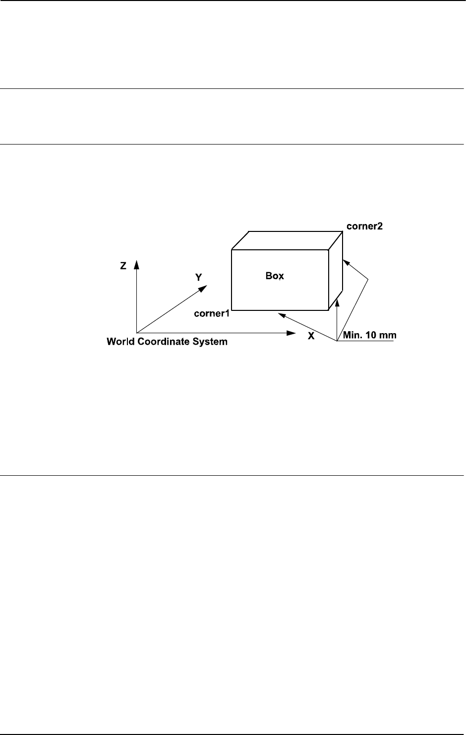
1 Instructions
1.250. WZBoxDef - Define a box-shaped world zone
World Zones
3HAC 16581-1 Revision: J732
© Copyright 2004-2010 ABB. All rights reserved.
1.250. WZBoxDef - Define a box-shaped world zone
Usage
WZBoxDef (World Zone Box Definition) is used to define a world zone that has the shape of
a straight box with all its sides parallel to the axes of the World Coordinate System.
Basic examples
Basic examples of the instruction
WZBoxDef are illustrated below.
Example 1
xx0500002205
VAR shapedata volume;
CONST pos corner1:=[200,100,100];
CONST pos corner2:=[600,400,400];
...
WZBoxDef \Inside, volume, corner1, corner2;
Define a straight box with coordinates parallel to the axes of the world coordinate system and
defined by the opposite corners
corner1 and corner2.
Arguments
WZBoxDef [\Inside] | [\Outside] Shape LowPoint HighPoint
[\Inside]
Data type: switch
Define the volume inside the box.
[\Outside]
Data type: switch
Define the volume outside the box (inverse volume).
One of the arguments
\Inside or \Outside must be specified.
Shape
Data type: shapedata
Variable for storage of the defined volume (private data for the system).
Continues on next page

1 Instructions
1.250. WZBoxDef - Define a box-shaped world zone
World Zones
7333HAC 16581-1 Revision: J
© Copyright 2004-2010 ABB. All rights reserved.
LowPoint
Data type: pos
Position (x,y,z) in mm defining one lower corner of the box.
HighPoint
Data type: pos
Position (x,y,z) in mm defining the corner diagonally opposite to the previous one.
Program execution
The definition of the box is stored in the variable of type
shapedata (argument Shape), for
future use in
WZLimSup or WZDOSet instructions.
Limitations
The
LowPoint and HighPoint positions must be valid for opposite corners (with different
x, y, and z coordinate values).
If the robot is used to point out the
LowPoint or HighPoint then work object wobj0 must
be active (use of component
trans in robtarget e.g. p1.trans as argument).
Syntax
WZBoxDef
[[’\’Inside] | [’\’Outside]’,’]
[LowPoint’:=’]<expression (IN) of pos>’,’
[Shape’:=’]<variable (VAR) of shapedata>’,’
[HighPoint’:=’]<expression (IN) of pos>’;’
Related information
For information about See
World Zones Technical reference manual - RAPID overview,
section Motion and I/O principles - World zones
World zone shape shapedata - World zone shape data on page 1179
Define sphere-shaped world zone WZSphDef - Define a sphere-shaped world zone on
page 756
Define cylinder-shaped world zone WZCylDef - Define a cylinder-shaped world zone on
page 734
Define a world zone for home joints WZHomeJointDef - Define a world zone for home
joints on page 746
Define a world zone for limit joints WZLimJointDef - Define a world zone for limitation
in joints on page 749
Activate world zone limit supervision WZLimSup - Activate world zone limit supervision
on page 753
Activate world zone digital output set WZDOSet - Activate world zone to set digital output
on page 738
Continued
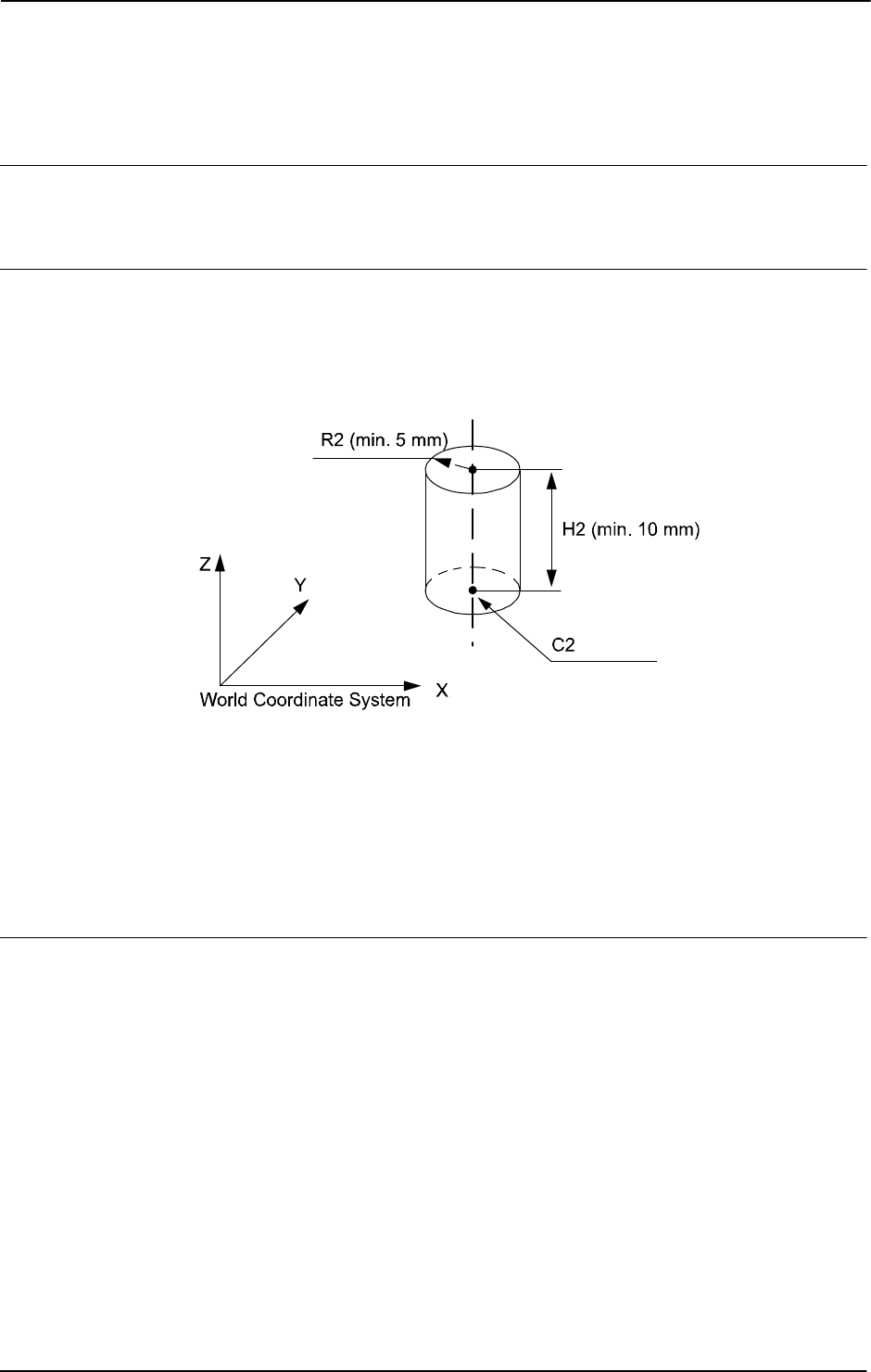
1 Instructions
1.251. WZCylDef - Define a cylinder-shaped world zone
World Zones
3HAC 16581-1 Revision: J734
© Copyright 2004-2010 ABB. All rights reserved.
1.251. WZCylDef - Define a cylinder-shaped world zone
Usage
WZCylDef (World Zone Cylinder Definition) is used to define a world zone that has the shape
of a cylinder with the cylinder axis parallel to the z-axis of the World Coordinate System.
Basic examples
Basic examples of the instruction
WZCylDef are illustrated below.
Example 1
xx0500002206
VAR shapedata volume;
CONST pos C2:=[300,200,200];
CONST num R2:=100;
CONST num H2:=200;
...
WZCylDef \Inside, volume, C2, R2, H2;
Define a cylinder with the center of the bottom circle in C2, radius R2, and height H2.
Arguments
WZCylDef [\Inside] | [\Outside] Shape CentrePoint Radius Height
[\Inside]
Data type: switch
Define the volume inside the cylinder.
[\Outside]
Data type: switch
Define the volume outside the cylinder (inverse volume).
One of the arguments
\Inside or \Outside must be specified.
Shape
Data type: shapedata
Variable for storage of the defined volume (private data for the system).
Continues on next page

1 Instructions
1.251. WZCylDef - Define a cylinder-shaped world zone
World Zones
7353HAC 16581-1 Revision: J
© Copyright 2004-2010 ABB. All rights reserved.
CentrePoint
Data type: pos
Position (x,y,z) in mm defining the center of one circular end of the cylinder.
Radius
Data type: num
The radius of the cylinder in mm.
Height
Data type: num
The height of the cylinder in mm. If it is positive (+z direction), the CentrePoint argument
is the center of the lower end of the cylinder (as in the above example). If it is negative (-z
direction) then the
CentrePoint argument is the center of the upper end of the cylinder.
Program execution
The definition of the cylinder is stored in the variable of type
shapedata (argument Shape)
for future use in
WZLimSup or WZDOSet instructions.
Limitations
If the robot is used to point out the
CentrePoint then the work object wobj0 must be active
(use of component
trans in robtarget e.g. p1.trans as argument).
Syntax
WZCylDef
[’\’Inside] | [’\’Outside]’,’
[Shape’:=’]<variable (VAR) of shapedata>’,’
[centerPoint’:=’]<expression (IN) of pos>’,’
[Radius’:=’]<expression (IN) of num>’,’
[Height’:=’]<expression (IN) of num>’;’
Related information
For information about See
World Zones Technical reference manual - RAPID overview,
section Motion and I/O principles - World zones
World zone shape shapedata - World zone shape data on page 1179
Define box-shaped world zone WZBoxDef - Define a box-shaped world zone on
page 732
Define sphere-shaped world zone WZSphDef - Define a sphere-shaped world zone
on page 756
Define a world zone for home joints WZHomeJointDef - Define a world zone for home
joints on page 746
Define a world zone for limit joints WZLimJointDef - Define a world zone for limitation
in joints on page 749
Activate world zone limit supervision WZLimSup - Activate world zone limit supervision
on page 753
Activate world zone digital output set WZDOSet - Activate world zone to set digital output
on page 738
Continued

1 Instructions
1.252. WZDisable - Deactivate temporary world zone supervision
World Zones
3HAC 16581-1 Revision: J736
© Copyright 2004-2010 ABB. All rights reserved.
1.252. WZDisable - Deactivate temporary world zone supervision
Usage
WZDisable (World Zone Disable) is used to deactivate the supervision of a temporary world
zone previously defined either to stop the movement or to set an output.
Basic examples
Basic examples of the instruction
WZDisable are illustrated below.
Example 1
VAR wztemporary wzone;
...
PROC...
WZLimSup \Temp, wzone, volume;
MoveL p_pick, v500, z40, tool1;
WZDisable wzone;
MoveL p_place, v200, z30, tool1;
ENDPROC
When moving to p_pick, the position of the robot’s TCP is checked so that it will not go
inside the specified volume
wzone. This supervision is not performed when going to
p_place.
Arguments
WZDisable WorldZone
WorldZone
Data type: wztemporary
Variable or persistent variable of type wztemporary, which contains the identity of the world
zone to be deactivated.
Program execution
The temporary world zone is deactivated. This means that the supervision of the robot’s TCP,
relative to the corresponding volume, is temporarily stopped. It can be re-activated via the
WZEnable instruction.
Limitations
Only a temporary world zone can be deactivated. A stationary world zone is always active.
Syntax
WZDisable
[WorldZone’:=’]<variable or persistent (INOUT) of
wztemporary>’;’
Continues on next page

1 Instructions
1.252. WZDisable - Deactivate temporary world zone supervision
World Zones
7373HAC 16581-1 Revision: J
© Copyright 2004-2010 ABB. All rights reserved.
Related information
For information about See
World Zones Technical reference manual - RAPID overview,
section Motion and I/O principles - World zones
World zone shape shapedata - World zone shape data on page 1179
Temporary world zone data wztemporary - Temporary world zone data on page
1230
Activate world zone limit supervision WZLimSup - Activate world zone limit supervision on
page 753
Activate world zone set digital output WZDOSet - Activate world zone to set digital output
on page 738
Activate world zone WZEnable - Activate temporary world zone
supervision on page 742
Erase world zone WZFree - Erase temporary world zone supervision
on page 744
Continued

1 Instructions
1.253. WZDOSet - Activate world zone to set digital output
World Zones
3HAC 16581-1 Revision: J738
© Copyright 2004-2010 ABB. All rights reserved.
1.253. WZDOSet - Activate world zone to set digital output
Usage
WZDOSet (World Zone Digital Output Set) is used to define the action and to activate a world
zone for supervision of the robot movements.
After this instruction is executed, when the robot’s TCP or the robot/external axes (zone in
joints) is inside the defined world zone or is approaching close to it, a digital output signal is
set to the specified value.
Basic examples
Basic examples of the instruction
WZDOSet are illustrated below.
See also More examples on page 740.
Example 1
VAR wztemporary service;
PROC zone_output()
VAR shapedata volume;
CONST pos p_service:=[500,500,700];
...
WZSphDef \Inside, volume, p_service, 50;
WZDOSet \Temp, service \Inside, volume, do_service, 1;
ENDPROC
Definition of temporary world zone service in the application program that sets the signal
do_service when the robot’s TCP is inside the defined sphere during program execution or
when jogging.
Arguments
WZDOSet [\Temp] | [\Stat] WorldZone [\Inside] | [\Before] Shape
Signal SetValue
[\Temp]
Temporary
Data type:
switch
The world zone to define is a temporary world zone.
[\Stat]
Stationary
Data type:
switch
The world zone to define is a stationary world zone.
One of the arguments
\Temp or \Stat must be specified.
Continues on next page

1 Instructions
1.253. WZDOSet - Activate world zone to set digital output
World Zones
7393HAC 16581-1 Revision: J
© Copyright 2004-2010 ABB. All rights reserved.
WorldZone
Data type: wztemporary or wzstationary
Variable or persistent variable, that will be updated with the identity (numeric value) of the
world zone.
If using the switch
\Temp, the data type must be wztemporary. If using the switch \Stat,
the data type must be
wzstationary.
[\Inside]
Data type: switch
The digital output signal will be set when the robot’s TCP or specified axes are inside the
defined volume.
[\Before]
Data type: switch
The digital output signal will be set before the robot’s TCP or specified axes reaches the
defined volume (as soon as possible before the volume).
One of the arguments
\Inside or \Before must be specified.
Shape
Data type: shapedata
The variable that defines the volume of the world zone.
Signal
Data type: signaldo
The name of the digital output signal that will be changed.
If a stationary worldzone is used then the signal must be written as protected for access from
the user (RAPID, FP). Set Access Level for the signal in System Parameters or specified axes.
SetValue
Data type: dionum
Desired value of the signal (0 or 1) when the robot’s TCP is inside the volume or just before
it enters the volume.
When outside or just outside the volume then the signal is set to the opposite value.
Program execution
The defined world zone is activated. From this moment the robot’s TCP position (or robot/
external joint position) is supervised, and the output will be set when the robot’s TCP position
(or robot/external joint position) is inside the volume (
\Inside) or comes close to the border
of the volume (
\Before).
If using
WZHomeJointDef or WZLimJointDef together with WZDOSet then the digital
output signal is set only if all active axes with joint space supervision are before or inside the
joint space.
Continued
Continues on next page

1 Instructions
1.253. WZDOSet - Activate world zone to set digital output
World Zones
3HAC 16581-1 Revision: J740
© Copyright 2004-2010 ABB. All rights reserved.
More examples
More examples of how to use the instruction
WZDOSet are illustrated below.
Example 1
VAR wztemporary home;
VAR wztemporary service;
PERS wztemporary equip1:=[0];
PROC main()
...
! Definition of all temporary world zones
zone_output;
...
! equip1 in robot work area
WZEnable equip1;
...
! equip1 out of robot work area
WZDisable equip1;
...
! No use for equip1 any more
WZFree equip1;
...
ENDPROC
PROC zone_output()
VAR shapedata volume;
CONST pos p_home:=[800,0,800];
CONST pos p_service:=[800,800,800];
CONST pos p_equip1:=[-800,-800,0];
...
WZSphDef \Inside, volume, p_home, 50;
WZDOSet \Temp, home \Inside, volume, do_home, 1;
WZSphDef \Inside, volume, p_service, 50;
WZDOSet \Temp, service \Inside, volume, do_service, 1;
WZCylDef \Inside, volume, p_equip1, 300, 1000;
WZLimSup \Temp, equip1, volume;
! equip1 not in robot work area
WZDisable equip1;
ENDPROC
Definition of temporary world zones home and service in the application program, that sets
the signals
do_home and do_service, when the robot is inside the sphere home or service
respectively during program execution or when jogging.
Also, definition of a temporary world zone
equip1, which is active only in the part of the
robot program when
equip1 is inside the working area for the robot. At that time the robot
stops before entering the
equip1 volume, both during program execution and manual
jogging.
equip1 can be disabled or enabled from other program tasks by using the persistent
variable
equip1 value.
Continued
Continues on next page

1 Instructions
1.253. WZDOSet - Activate world zone to set digital output
World Zones
7413HAC 16581-1 Revision: J
© Copyright 2004-2010 ABB. All rights reserved.
Limitations
A world zone cannot be redefined by using the same variable in the argument
WorldZone.
A stationary world zone cannot be deactivated, activated again, or erased in the RAPID
program.
A temporary world zone can be deactivated (
WZDisable), activated again (WZEnable), or
erased (
WZFree) in the RAPID program.
Syntax
WZDOSet
[[’\’Temp] | [’\’Stat]’,’]
[WorldZone’:=’]<variable or persistent (INOUT) of wztemporary>
[’\’Inside] | [’\’Before] ’,’
[Shape’:=’]<variable (VAR) of shapedata>’,’
[Signal’:=’]<variable (VAR) of signaldo>’,’
[SetValue’:=’]<expression (IN) of dionum>’;’
Related information
For information about See
World Zones Technical reference manual - RAPID overview,
section Motion and I/O principles - World zones
World zone shape shapedata - World zone shape data on page 1179
Temporary world zone wztemporary - Temporary world zone data on
page 1230
Stationary world zone wzstationary - Stationary world zone data on page
1228
Define straight box-shaped world zone WZBoxDef - Define a box-shaped world zone on
page 732
Define sphere-shaped world zone WZSphDef - Define a sphere-shaped world zone
on page 756
Define cylinder-shaped world zone WZCylDef - Define a cylinder-shaped world zone
on page 734
Define a world zone for home joints WZHomeJointDef - Define a world zone for home
joints on page 746
Activate world zone limit supervision WZLimSup - Activate world zone limit supervision
on page 753
Signal access level Technical reference manual - System parameters,
section I/O - Signal - Access Level
Continued

1 Instructions
1.254. WZEnable - Activate temporary world zone supervision
World Zones
3HAC 16581-1 Revision: J742
© Copyright 2004-2010 ABB. All rights reserved.
1.254. WZEnable - Activate temporary world zone supervision
Usage
WZEnable (World Zone Enable) is used to re-activate the supervision of a temporary world
zone, previously defined either to stop the movement or to set an output.
Basic examples
Basic examples of the instruction
WZEnable are illustrated.
Example 1
VAR wztemporary wzone;
...
PROC ...
WZLimSup \Temp, wzone, volume;
MoveL p_pick, v500, z40, tool1;
WZDisable wzone;
MoveL p_place, v200, z30, tool1;
WZEnable wzone;
MoveL p_home, v200, z30, tool1;
ENDPROC
When moving to p_pick, the position of the robot’s TCP is checked so that it will not go
inside the specified volume
wzone. This supervision is not performed when going to
p_place but is reactivated before going to p_home.
Arguments
WZEnable WorldZone
WorldZone
Data type: wztemporary
Variable or persistent variable of the type wztemporary, which contains the identity of the
world zone to be activated.
Program execution
The temporary world zone is re-activated. Please note that a world zone is automatically
activated when it is created. It need only be re-activated when it has previously been
deactivated by
WZDisable.
Limitations
Only a temporary world zone can be deactivated and reactivated. A stationary world zone is
always active.
Syntax
WZEnable
[WorldZone’:=’]<variable or persistent (INOUT) of
wztemporary>’;’
Continues on next page

1 Instructions
1.254. WZEnable - Activate temporary world zone supervision
World Zones
7433HAC 16581-1 Revision: J
© Copyright 2004-2010 ABB. All rights reserved.
Related information
For information about See
World Zones Technical reference manual - RAPID overview,
section Motion and I/O principles - World zones
World zone shape shapedata - World zone shape data on page 1179
Temporary world zone data wztemporary - Temporary world zone data on page
1230
Activate world zone limit supervision WZLimSup - Activate world zone limit supervision
on page 753
Activate world zone set digital output WZDOSet - Activate world zone to set digital output
on page 738
Deactivate world zone WZDisable - Deactivate temporary world zone
supervision on page 736
Erase world zone WZFree - Erase temporary world zone supervision
on page 744
Continued

1 Instructions
1.255. WZFree - Erase temporary world zone supervision
World Zones
3HAC 16581-1 Revision: J744
© Copyright 2004-2010 ABB. All rights reserved.
1.255. WZFree - Erase temporary world zone supervision
Usage
WZFree (World Zone Free) is used to erase the definition of a temporary world zone,
previously defined either to stop the movement or to set an output.
Basic examples
Basic examples of the instruction
WZFree are illustrated below.
Example 1
VAR wztemporary wzone;
...
PROC ...
WZLimSup \Temp, wzone, volume;
MoveL p_pick, v500, z40, tool1;
WZDisable wzone;
MoveL p_place, v200, z30, tool1;
WZEnable wzone;
MoveL p_home, v200, z30, tool1;
WZFree wzone;
ENDPROC
When moving to p_pick, the position of the robot’s TCP is checked so that it will not go
inside a specified volume
wzone. This supervision is not performed when going to p_place
but is reactivated before going to
p_home. When this position is reached then the world zone
definition is erased.
Arguments
WZFree WorldZone
WorldZone
Data type: wztemporary
Variable or persistent variable of the type wztemporary, which contains the identity of the
world zone to be erased.
Program execution
The temporary world zone is first deactivated and then its definition is erased.
Once erased, a temporary world zone cannot be re-activated or deactivated.
Limitations
Only a temporary world zone can be deactivated, reactivated, or erased. A stationary world
zone is always active.
Syntax
WZFree
[WorldZone’:=’]<variable or persistent (INOUT) of
wztemporary>’;’
Continues on next page

1 Instructions
1.255. WZFree - Erase temporary world zone supervision
World Zones
7453HAC 16581-1 Revision: J
© Copyright 2004-2010 ABB. All rights reserved.
Related information
For information about See
World Zones Technical reference manual - RAPID overview,
section Motion and I/O principles - World zones
World zone shape shapedata - World zone shape data on page 1179
Temporary world zone data wztemporary - Temporary world zone data on page
1230
Activate world zone limit supervision WZLimSup - Activate world zone limit supervision
on page 753
Activate world zone set digital output WZDOSet - Activate world zone to set digital output
on page 738
Deactivate world zone WZDisable - Deactivate temporary world zone
supervision on page 736
Activate world zone WZEnable - Activate temporary world zone
supervision on page 742
Continued

1 Instructions
1.256. WZHomeJointDef - Define a world zone for home joints
World Zones
3HAC 16581-1 Revision: J746
© Copyright 2004-2010 ABB. All rights reserved.
1.256. WZHomeJointDef - Define a world zone for home joints
Usage
WZHomeJointDef (World Zone Home Joint Definition) is used to define a world zone in
joints coordinates for both the robot and external axes to be used as a HOME or SERVICE
position.
Basic examples
Basic examples of the instruction
WZHomeJointDef are illustrated below.
Example 1
VAR wzstationary home;
...
PROC power_on()
VAR shapedata joint_space;
CONST jointtarget home_pos := [ [ 0, 0, 0, 0, 0, -45], [ 0, 9E9,
9E9, 9E9, 9E9, 9E9] ];
CONST jointtarget delta_pos := [ [ 2, 2, 2, 2, 2, 2], [ 5, 9E9,
9E9, 9E9, 9E9, 9E9] ];
...
WZHomeJointDef \Inside, joint_space, home_pos, delta_pos;
WZDOSet \Stat, home \Inside, joint_space, do_home, 1;
ENDPROC
Definition and activation of stationary world zone home, that sets the signal do_home to 1,
when all robot axes and the external axis
extax.eax_a are at the joint position home_pos
(within +/-
delta_pos for each axis) during program execution and jogging. The variable
joint_space of data type shapedata are used to transfer data from the instruction
WZHomeJointDef to the instruction WZDOSet.
Arguments
WZHomeJointDef [\Inside] | [\Outside] Shape MiddleJointVal
DeltaJointVal
[\Inside]
Data type: switch
Define the joint space inside the MiddleJointVal +/- DeltaJointVal.
[\Outside]
Data type: switch
Define the joint space outside the MiddleJointVal +/- DeltaJointVal (inverse joint
space).
Shape
Data type: shapedata
Variable for storage of the defined joint space (private data for the system).
Continues on next page
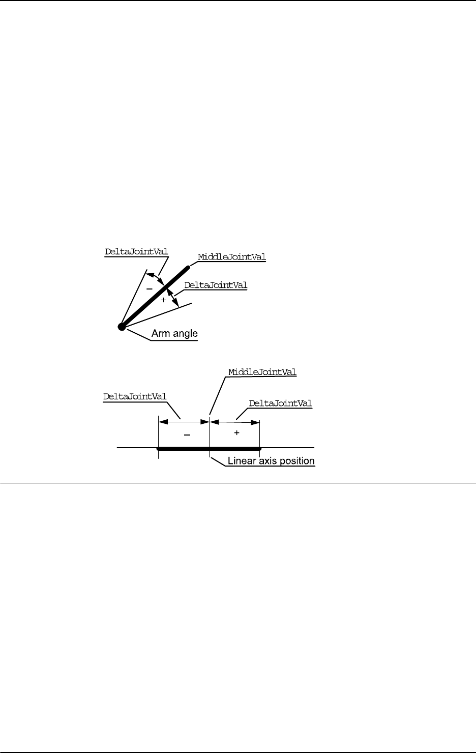
1 Instructions
1.256. WZHomeJointDef - Define a world zone for home joints
World Zones
7473HAC 16581-1 Revision: J
© Copyright 2004-2010 ABB. All rights reserved.
MiddleJointVal
Data type: jointtarget
The position in joint coordinates for the center of the joint space to define. Specifies for each
robot axis and external axis (degrees for rotational axes and mm for linear axes). Specifies in
absolute joints (not in offset coordinate system
EOffsSet-EOffsOn for external axes).
Value 9E9 for some axis means that the axis should not be supervised. Non-active
external axis also gives 9E9 at programming time.
DeltaJointVal
Data type: jointtarget
The +/- delta position in joint coordinates from the center of the joint space. The value must
be greater than 0 for all axes to supervise.
The following figure shows the definition of joint space for rotational axis.
xx0500002208
The following figure shows the definition of joint space for linear axis.
xx0500002209
Program execution
The definition of the joint space is stored in the variable of type
shapedata (argument
Shape) for future use in WZLimSup or WZDOSet instructions.
If use of
WZHomeJointDef together with WZDOSet then the digital output signal is set but
only if all active axes with joint space supervision are before or inside the joint space.
If use of
WZHomeJointDef with outside joint space (argument \Outside) together with
WZLimSup then the robot is stopped as soon as one active axes with joint space supervision
reach the joint space.
If use of
WZHomeJointDef with inside joint space (argument \Inside) together with
WZLimSup then the robot is stopped as soon as the last active axes with joint space
supervision reach the joint space. That means that one or several axes, but not all active and
supervised axes, can be inside the joint space at the same time.
At execution of the instruction
ActUnit or DeactUnit for activation or deactivation of
mechanical units, the supervision status for HOME position or work area limitation will be
updated.
Continued
Continues on next page

1 Instructions
1.256. WZHomeJointDef - Define a world zone for home joints
World Zones
3HAC 16581-1 Revision: J748
© Copyright 2004-2010 ABB. All rights reserved.
Limitations
-
Only active mechanical units and their active axes at activation time of the world zone (with
instruction
WZDOSet respectively WZLimSup), are included in the supervision of the HOME
position respectively to the limitation of the working area. Besides that, the mechanical unit
and its axes must still be active at the program movement or jogging to be supervised.
For example, if one axis with supervision is outside its HOME joint position but is
deactivated then it does not prevent the digital output signal for the HOME joint position to
be set if all other active axes with joint space supervision are inside the HOME joint position.
At activation of that axis again it will be included in the supervision and the robot system will
then be outside the HOME joint position and the digital output will be reset.
Syntax
WZHomeJointDef
[[’\’Inside] | [’\’Outside]’,’]
[Shape’:=’]<variable (VAR) of shapedata>’,’
[MiddleJointVal’ :=’]<expression (IN) of jointtarget>’,’
[DeltaJointVal’ :=’]<expression (IN) of jointtarget>’;’
Related information
For information about See
World Zones Technical reference manual - RAPID overview,
section Motion and I/O principles - World zones
World zone shape shapedata - World zone shape data on page
1179
Define box-shaped world zone WZBoxDef - Define a box-shaped world zone
on page 732
Define cylinder-shaped world zone WZCylDef - Define a cylinder-shaped world
zone on page 734
Define sphere-shaped world zone WZSphDef - Define a sphere-shaped world
zone on page 756
Define a world zone for limit joints WZLimJointDef - Define a world zone for
limitation in joints on page 749
Activate world zone limit supervision WZLimSup - Activate world zone limit
supervision on page 753
Activate world zone digital output set WZDOSet - Activate world zone to set digital
output on page 738
Continued

1 Instructions
1.257. WZLimJointDef - Define a world zone for limitation in joints
World Zones
7493HAC 16581-1 Revision: J
© Copyright 2004-2010 ABB. All rights reserved.
1.257. WZLimJointDef - Define a world zone for limitation in joints
Usage
WZLimJointDef (World Zone Limit Joint Definition) is used to define a world zone in joints
coordinates for both the robot and external axes, to be used for limitation of the working area.
With
WZLimJointDef it is possible to limit the working area for each robot and external axes
in the RAPID program, besides the limitation that can be done with system parameters
Motion - Arm - robx_y - Upper Joint Bound ... Lower Joint Bound.
Basic examples
Basic examples of the instruction
WZLimJointDef are illustrated below.
Example 1
VAR wzstationary work_limit;
...
PROC power_on()
VAR shapedata joint_space;
CONST jointtarget low_pos:= [ [ -90, 9E9, 9E9, 9E9, 9E9, 9E9],
[ -1000, 9E9, 9E9, 9E9, 9E9, 9E9]];
CONST jointtarget high_pos := [ [ 90, 9E9, 9E9, 9E9,9E9, 9E9],
[ 9E9, 9E9, 9E9, 9E9, 9E9, 9E9] ];
...
WZLimJointDef \Outside, joint_space, low_pos, high_pos;
WZLimSup \Stat, work_limit, joint_space;
ENDPROC
Definition and activation of stationary world zone work_limit, that limit the working area
for robot axis 1 to -90 and +90 degrees and the external axis
extax.eax_a to -1000 mm
during program execution and jogging. The variable
joint_space of data type shapedata
are used to transfer data from the instruction
WZLimJointDef to the instruction WZLimSup.
Arguments
WZLimJointDef [\Inside] | [\Outside] Shape LowJointVal
HighJointVal
[\Inside]
Data type: switch
Define the joint space inside the LowJointVal ... HighJointVal.
[\Outside]
Data type: switch
Define the joint space outside the LowJointVal ... HighJointVal (inverse joint space).
Shape
Data type: shapedata
Variable for storage of the defined joint space (private data for the system).
Continues on next page
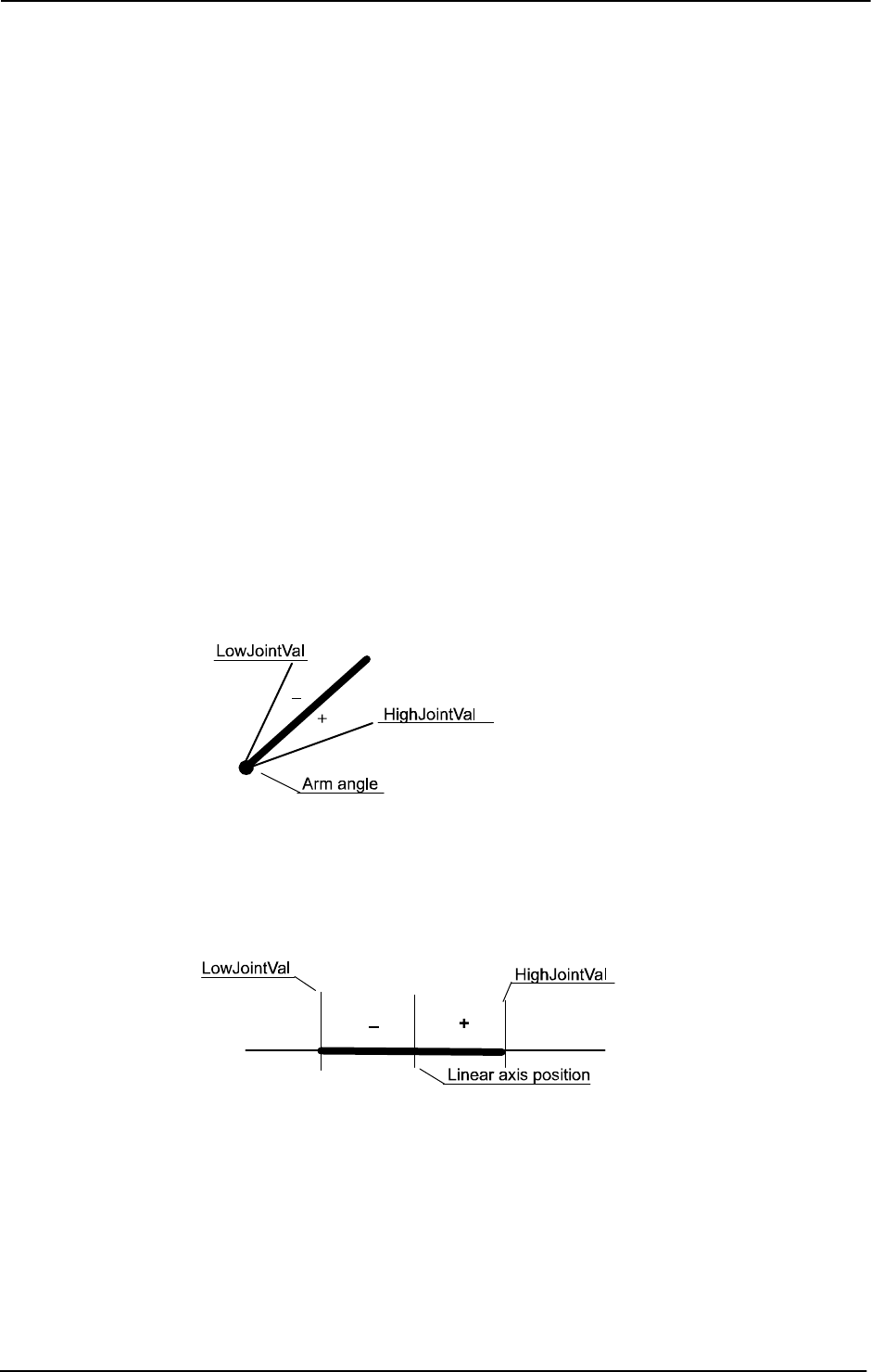
1 Instructions
1.257. WZLimJointDef - Define a world zone for limitation in joints
World Zones
3HAC 16581-1 Revision: J750
© Copyright 2004-2010 ABB. All rights reserved.
LowJointVal
Data type: jointtarget
The position in joint coordinates for the low limit of the joint space to define. Specifies for
each robot axes and external axes (degrees for rotational axes and mm for linear axes).
Specifies in absolute joints (not in offset coordinate system
EOffsSet or EOffsOn for
external axes). Value
9E9 for some axis means that the axis should not be supervised for low
limit. Non-active external axis also gives
9E9 at programming time.
HighJointVal
Data type: jointtarget
The position in joint coordinates for the high limit of the joint space to define. Specifies for
each robot axes and external axes (degrees for rotational axes and mm for linear axes).
Specifies in absolute joints (not in offset coordinate system
EOffsSet or EOffsOn for
external axes). Value
9E9 for an axis means that the axis should not be supervised for high
limit. Non-active external axis also gives
9E9 at programming time.
HighJointVal minus LowJointVal for each axis must be greater than 0 for all axes to
supervise.
The figure below shows definition of joint space for rotating axis.
xx0500002281
The figure below shows definition of joint space for linear axis.
xx0500002282
Continued
Continues on next page

1 Instructions
1.257. WZLimJointDef - Define a world zone for limitation in joints
World Zones
7513HAC 16581-1 Revision: J
© Copyright 2004-2010 ABB. All rights reserved.
Program execution
The definition of the joint space is stored in the variable of type
shapedata (argument
Shape) for future use in WZLimSup or WZDOSet instructions.
If using
WZLimJointDef together with WZDOSet then the digital output signal is set, only if
all active axes with joint space supervision are before or inside the joint space.
If using
WZLimJointDef with outside joint space (argument \Outside) together with
WZLimSup then the robot is stopped as soon as one active axes with joint space supervision
reaches the joint space.
If using
WZLimJointDef with inside joint space (argument \Inside) together with
WZLimSup then the robot is stopped as soon as the last active axes with joint space
supervision reaches the joint space. That means that one or several axes but not all active and
supervised axes can be inside the joint space at the same time.
At execution of the instruction
ActUnit or DeactUnit the supervision status will be
updated.
Limitations
-
WAR NIN G!
Only active mechanical units and its active axes at activation time of the world zone (with
instruction
WZDOSet respective to WZLimSup), are included in the supervision of the HOME
position respectively the limitation of the working area. Besides that, the mechanical unit and
its axes must still be active at the program movement or jogging to be supervised.
For example, if one axis with supervision is outside its HOME joint position but is
deactivated then it does not prevent the digital output signal for the HOME joint position to
be set if all other active axes with joint space supervision are inside the HOME joint position.
At activation of that axis again, it will be included in the supervision and the robot system
will the be outside the HOME joint position and the digital output will be reset.
Syntax
WZLimJointDef
[[’\’Inside] | [’\’Outside]’,’]
[Shape’:=’]<variable (VAR) of shapedata>’,’
[LowJointVal’:=’]<expression (IN) of jointtarget>’,’
[HighJointVal’:=’]<expression (IN) of jointtarget>’;’
Continued
Continues on next page

1 Instructions
1.257. WZLimJointDef - Define a world zone for limitation in joints
World Zones
3HAC 16581-1 Revision: J752
© Copyright 2004-2010 ABB. All rights reserved.
Related information
For information about See
World Zones Technical reference manual - RAPID overview,
section Motion and I/O principles - World zones
World zone shape shapedata - World zone shape data on page 1179
Define box-shaped world zone WZBoxDef - Define a box-shaped world zone on
page 732
Define cylinder-shaped world zone WZCylDef - Define a cylinder-shaped world zone
on page 734
Define sphere-shaped world zone WZSphDef - Define a sphere-shaped world zone
on page 756
Define a world zone for home joints WZHomeJointDef - Define a world zone for home
joints on page 746
Activate world zone limit supervision WZLimSup - Activate world zone limit supervision
on page 753
Activate world zone digital output set WZDOSet - Activate world zone to set digital
output on page 738
Continued

1 Instructions
1.258. WZLimSup - Activate world zone limit supervision
World Zones
7533HAC 16581-1 Revision: J
© Copyright 2004-2010 ABB. All rights reserved.
1.258. WZLimSup - Activate world zone limit supervision
Usage
WZLimSup (World Zone Limit Supervision) is used to define the action and to activate a world
zone for supervision of the working area of the robot or external axes.
After this instruction is executed, when the robot’s TCP reaches the defined world zone or
when the robot/external axes reaches the defined world zone in joints, then the movement is
stopped both during program execution and when jogging.
Basic examples
Basic examples of the instruction
WZLimSup are illustrated below.
See also More examples on page 754.
Example 1
VAR wzstationary max_workarea;
...
PROC POWER_ON()
VAR shapedata volume;
...
WZBoxDef \Outside, volume, corner1, corner2;
WZLimSup \Stat, max_workarea, volume;
ENDPROC
Definition and activation of stationary world zone max_workarea, with the shape of the area
outside a box (temporarily stored in
volume) and the action work-area supervision. The robot
stops with an error message before entering the area outside the box.
Arguments
WZLimSup [\Temp] | [\Stat] WorldZone Shape
[\Temp]
Temporary
Data type:
switch
The world zone to define is a temporary world zone.
[\Stat]
Stationary
Data type:
switch
The world zone to define is a stationary world zone.
One of the arguments
\Temp or \Stat must be specified.
WorldZone
Data type: wztemporary or wzstationary
Variable or persistent variable that will be updated with the identity (numeric value) of the
world zone.
If using switch
\Temp, the data type must be wztemporary. If using switch \Stat, the data
type must be
wzstationary.
Continues on next page

1 Instructions
1.258. WZLimSup - Activate world zone limit supervision
World Zones
3HAC 16581-1 Revision: J754
© Copyright 2004-2010 ABB. All rights reserved.
Shape
Data type: shapedata
The variable that defines the volume of the world zone.
Program execution
The defined world zone is activated. From this moment the robot’s TCP position or the robot/
external axes joint position are supervised. If it reaches the defined area then the movement
is stopped.
If using
WZLimJointDef or WZHomeJointDef with outside joint space (argument
\Outside) together with WZLimSup then the robot is stopped as soon as one active axes with
joint space supervision reaches the joint space.
If using
WZLimJointDef or WZHomeJointDef with inside joint space (argument \Inside)
together with
WZLimSup then the robot is stopped as soon as the last active axes with joint
space supervision reaches the joint space. That means that one or several axes but not all
active and supervised axes can be inside the joint space at the same time.
At execution of the instruction
ActUnit or DeactUnit the supervision status will be
updated.
More examples
More examples of how to use the instruction
WZLimSup are illustrated below.
Example 1
VAR wzstationary box1_invers;
VAR wzstationary box2;
PROC wzone_power_on()
VAR shapedata volume;
CONST pos box1_c1:=[500,-500,0];
CONST pos box1_c2:=[-500,500,500];
CONST pos box2_c1:=[500,-500,0];
CONST pos box2_c2:=[200,-200,300];
...
WZBoxDef \Outside, volume, box1_c1, box1_c2;
WZLimSup \Stat, box1_invers, volume;
WZBoxDef \Inside, volume, box2_c1, box2_c2;
WZLimSup \Stat, box2, volume;
ENDPROC
Limitation of work area for the robot with the following stationary world zones:
• Outside working area when outside box1_invers
• Outside working area when inside box2
If this routine is connected to the system event POWER ON then these world zones will
always be active in the system, both for program movements and manual jogging.
Continued
Continues on next page

1 Instructions
1.258. WZLimSup - Activate world zone limit supervision
World Zones
7553HAC 16581-1 Revision: J
© Copyright 2004-2010 ABB. All rights reserved.
Limitations
A world zone cannot be redefined using the same variable in argument
WorldZone.
A stationary world zone cannot be deactivated, activated again, or erased in the RAPID
program.
A temporary world zone can be deactivated (
WZDisable), activated again (WZEnable), or
erased (
WZFree) in the RAPID program.
Syntax
WZLimSup
[[’\’Temp] | [’\Stat]’,’]
[WorldZone´:=´]<variable or persistent (INOUT) of
wztemporary>´,´
[Shape´:=´]<variable (VAR) of shapedata>´;´
Related information
For information about See
World Zones Technical reference manual - RAPID overview,
section Motion and I/O principles - World zones
World zone shape shapedata - World zone shape data on page 1179
Temporary world zone wztemporary - Temporary world zone data on
page 1230
Stationary world zone wzstationary - Stationary world zone data on page
1228
Define straight box-shaped world zone WZBoxDef - Define a box-shaped world zone on
page 732
Define sphere-shaped world zone WZSphDef - Define a sphere-shaped world zone
on page 756
Define cylinder-shaped world zone WZCylDef - Define a cylinder-shaped world zone
on page 734
Define a world zone for home joints WZHomeJointDef - Define a world zone for home
joints on page 746
Define a world zone for limit joints WZLimJointDef - Define a world zone for limitation
in joints on page 749
Activate world zone digital output set WZDOSet - Activate world zone to set digital
output on page 738
Continued
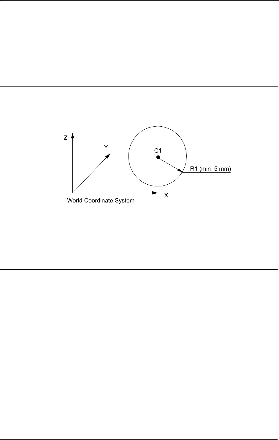
1 Instructions
1.259. WZSphDef - Define a sphere-shaped world zone
World Zones
3HAC 16581-1 Revision: J756
© Copyright 2004-2010 ABB. All rights reserved.
1.259. WZSphDef - Define a sphere-shaped world zone
Usage
WZSphDef (World Zone Sphere Definition) is used to define a world zone that has the shape
of a sphere.
Basic examples
Basic examples of the instruction
WZSphDef are illustrated below.
Example 1
xx0500002207
VAR shapedata volume;
CONST pos C1:=[300,300,200];
CONST num R1:=200;
...
WZSphDef \Inside, volume, C1, R1;
Define a sphere named volume by its center C1 and its radius R1.
Arguments
WZSphDef [\Inside] | [\Outside] Shape CentrePoint Radius
[\Inside]
Data type: switch
Define the volume inside the sphere.
[\Outside]
Data type: switch
Define the volume outside the sphere (inverse volume).
One of the arguments
\Inside or \Outside must be specified.
Shape
Data type: shapedata
Variable for storage of the defined volume (private data for the system).
CentrePoint
Data type: pos
Position (x,y,z) in mm defining the center of the sphere.
Continues on next page

1 Instructions
1.259. WZSphDef - Define a sphere-shaped world zone
World Zones
7573HAC 16581-1 Revision: J
© Copyright 2004-2010 ABB. All rights reserved.
Radius
Data type: num
The radius of the sphere in mm.
Program execution
The definition of the sphere is stored in the variable of type
shapedata (argument Shape),
for future use in
WZLimSup or WZDOSet instructions.
Limitations
If the robot is used to point out the
CentrePoint then the work object wobj0 must be active
(use of component
trans in robtarget e.g. p1.trans as argument).
Syntax
WZSphDef
[[’\’Inside] | [’\’Outside]’,’]
[Shape’:=’]<variable (VAR) of shapedata>’,’
[CentrePoint’:=’]<expression (IN) of pos>’,’
[Radius’:=’]<expression (IN) of num>’;’
Related information
For information about See
World Zones Technical reference manual - RAPID overview,
section Motion and I/O principles - World zones
World zone shape shapedata - World zone shape data on page 1179
Define box-shaped world zone WZBoxDef - Define a box-shaped world zone on
page 732
Define cylinder-shaped world zone WZCylDef - Define a cylinder-shaped world zone on
page 734
Define a world zone for home joints WZHomeJointDef - Define a world zone for home
joints on page 746
Define a world zone for limit joints WZLimJointDef - Define a world zone for limitation in
joints on page 749
Activate world zone limit supervision WZLimSup - Activate world zone limit supervision
on page 753
Activate world zone digital output set WZDOSet - Activate world zone to set digital output
on page 738
Continued

1 Instructions
1.259. WZSphDef - Define a sphere-shaped world zone
World Zones
3HAC 16581-1 Revision: J758
© Copyright 2004-2010 ABB. All rights reserved.

2 Functions
2.1. Abs - Gets the absolute value
RobotWare - OS
7593HAC 16581-1 Revision: J
© Copyright 2004-2010 ABB. All rights reserved.
2 Functions
2.1. Abs - Gets the absolute value
Usage
Abs is used to get the absolute value, i.e. a positive value of numeric data.
Basic examples
Basic examples of the function
Abs are illustrated below.
See also More examples on page 759.
Example 1
reg1 := Abs(reg2);
Reg1
is assigned the absolute value of reg2.
Return value
Data type:
num
The absolute value, i.e. a positive numeric value, e.g.:
Arguments
Abs (Value)
Value
Data type: num
The input value.
More examples
More examples of the function
Abs are illustrated below.
Example 1
TPReadNum no_of_parts, "How many parts should be produced? ";
no_of_parts := Abs(no_of_parts);
The operator is asked to input the number of parts to be produced. To ensure that the value is
greater than zero, the value given by the operator is made positive.
Syntax
Abs ’(’
[ Value ’:=’ ] < expression (IN) of num >’)’
A function with a return value of the data type num.
Input value Returned value
3 3
-3 3
-2.53 2.53
Continues on next page

2 Functions
2.1. Abs - Gets the absolute value
RobotWare - OS
3HAC 16581-1 Revision: J760
© Copyright 2004-2010 ABB. All rights reserved.
Related information
For information about See
Mathematical instructions and functions Technical reference manual - RAPID overview,
section RAPID summary - Mathematics
Continued

2 Functions
2.2. ACos - Calculates the arc cosine value
RobotWare - OS
7613HAC 16581-1 Revision: J
© Copyright 2004-2010 ABB. All rights reserved.
2.2. ACos - Calculates the arc cosine value
Usage
ACos (Arc Cosine) is used to calculate the arc cosine value.
Basic examples
Basic examples of the function
ACos are illustrated below.
Example 1
VAR num angle;
VAR num value;
...
...
angle := ACos(value);
angle
will get the arc cosine value of value.
Return value
Data type:
num
The arc cosine value, expressed in degrees, range [0, 180].
Arguments
ACos (Value)
Value
Data type: num
The argument value must be in range [-1, 1].
Limitations
The execution of the function
Acos(x) will give an error if x is outside the range [-1, 1].
Syntax
Acos’(’
[Value ’:=’] <expression (IN) of num>
’)’
A function with a return value of the data type num.
Related information
For information about See
Mathematical instructions and functions Technical reference manual - RAPID overview,
section RAPID Summary - Mathematics
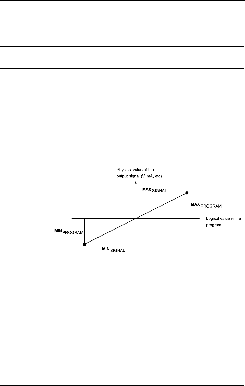
2 Functions
2.3. AOutput - Reads the value of an analog output signal
RobotWare - OS
3HAC 16581-1 Revision: J762
© Copyright 2004-2010 ABB. All rights reserved.
2.3. AOutput - Reads the value of an analog output signal
Usage
AOutput is used to read the current value of an analog output signal.
Basic examples
Basic examples of the function
AOutput are illustrated below.
Example 1
IF AOutput(ao4) > 5 THEN ...
If the current value of the signal ao4 is greater than 5, then ...
Return value
Data type:
num
The current value of the signal.
The current value is scaled (in accordance with the system parameters) before it is read by the
RAPID program. A diagram of how analog signal values are scaled is shown in the figure
below.
xx0500002408
Arguments
AOutput (Signal)
Signal
Data type: signalao
The name of the analog output to be read.
Error handling
The following recoverable error can be generated. The error can be handled in an error
handler. The system variable
ERRNO will be set to:
ERR_NORUNUNIT if there is no contact with the unit.
Continues on next page

2 Functions
2.3. AOutput - Reads the value of an analog output signal
RobotWare - OS
7633HAC 16581-1 Revision: J
© Copyright 2004-2010 ABB. All rights reserved.
Syntax
AOutput ’(’
[ Signal ’:=’ ] < variable (VAR) of signalao > ’)’
A function with a return value of data type num.
Related information
For information about See
Set an analog output signal SetAO - Changes the value of an analog output signal
on page 431
Input/Output instructions Technical reference manual - RAPID overview,
section RAPID Summary - Input and Output Signals
Input/Output functionality in general Technical reference manual - RAPID overview,
section Motion and I/O Principles - I/O principles
Configuration of I/O Technical reference manual - System parameters
Continued

2 Functions
2.4. ArgName - Gets argument name
RobotWare - OS
3HAC 16581-1 Revision: J764
© Copyright 2004-2010 ABB. All rights reserved.
2.4. ArgName - Gets argument name
Usage
ArgName (Argument Name) is used to get the name of the original data object for the current
argument or the current data.
Basic examples
Basic examples of the function
ArgName are illustrated below.
See also More examples on page 765.
Example 1
VAR num chales :=5;
...
proc1 chales;
PROC proc1 (num par1)
VAR string name;
...
name:=ArgName(par1);
TPWrite "Argument name "+name+" with value "\Num:=par1;
ENDPROC
The variable name is assigned the string value "chales" and on FlexPendant the following
string is written: "Argument name chales with value 5".
Return value
Data type:
string
The original data object name.
Arguments
ArgName (Parameter)
Parameter
Data type: anytype
The formal parameter identifier (for the routine in which ArgName is located) or the data
identity.
All types of data with structure atomic, record, record component, array, or array element can
be used.
Program execution
The function returns the original data object name for an entire object of the type constant,
variable, or persistent. The original data object can be global, local in the program module, or
local in a routine (normal RAPID scope rules).
If it is a part of a data object then the name of the whole data object is returned.
Continues on next page

2 Functions
2.4. ArgName - Gets argument name
RobotWare - OS
7653HAC 16581-1 Revision: J
© Copyright 2004-2010 ABB. All rights reserved.
More examples
More examples of the function
ArgName are illustrated below.
Convert from identifier to string
This function can also be used to convert from identifier to string, by specifying the
identifier in the argument
Parameter for any data object with global, local in module, or
local in routine scope:
VAR num chales :=5;
...
proc1;
PROC proc1 ()
VAR string name;
...
name:=ArgName(chales);
TPWrite "Global data object "+name+" has value "\Num:=chales;
ENDPROC
The variable name is assigned the string value "chales" and on FlexPendant the following
string is written: "Global data object chales has value 5".
Routine call in several steps
Note that the function returns the original data object name:
VAR num chales :=5;
...
proc1 chales;
...
PROC proc1 (num parameter1)
...
proc2 parameter1;
...
ENDPROC
PROC proc2 (num par1)
VAR string name;
...
name:=ArgName(par1);
TPWrite "Original data object name "+name+" with value"
\Num:=par1;
ENDPROC
The variable name is assigned the string value "chales" and on FlexPendant the following
string is written: "Original data object name chales with value 5".
Continued
Continues on next page

2 Functions
2.4. ArgName - Gets argument name
RobotWare - OS
3HAC 16581-1 Revision: J766
© Copyright 2004-2010 ABB. All rights reserved.
Error handling
If one of the following errors occurs then the system variable
ERRNO is set to ERR_ARGNAME:
• Argument is expression value
• Argument is not present
• Argument is of type switch
This error can then be handled in the error handler.
Syntax
ArgName ’(’
[ Parameter’:=’ ] < reference (REF) of any type> ’)’
A function with a return value of the data type string.
Related information
For information about See
String functions Technical reference manual - RAPID overview,
section RAPID summary - String functions
Definition of string string - Strings on page 1195
String values Technical reference manual - RAPID overview,
section Basic characteristics -Basic elements
Continued

2 Functions
2.5. ASin - Calculates the arc sine value
RobotWare - OS
7673HAC 16581-1 Revision: J
© Copyright 2004-2010 ABB. All rights reserved.
2.5. ASin - Calculates the arc sine value
Usage
ASin (Arc Sine) is used to calculate the arc sine value.
Basic examples
Basic examples of the function
ASin are illustrated below.
Example 1
VAR num angle;
VAR num value;
...
...
angle := ASin(value);
angle will get the arc sine value of value
Return value
Data type:
num
The arc sine value, expressed in degrees, range [-90, 90].
Arguments
ASin (Value)
Value
Data type: num
The argument value must be in range [-1, 1].
Limitations
The execution of the function
ASin(x) will give an error if x is outside the range [1, -1].
Syntax
ASin’(’
[Value ’:=’] <expression (IN) of num>
’)’
A function with a return value of the data type num.
Related information
For information about See
Mathematical instructions and functions Technical reference manual - RAPID
overview, section RAPID Summary -
Mathematics

2 Functions
2.6. ATan - Calculates the arc tangent value
RobotWare - OS
3HAC 16581-1 Revision: J768
© Copyright 2004-2010 ABB. All rights reserved.
2.6. ATan - Calculates the arc tangent value
Usage
ATan (Arc Tangent) is used to calculate the arc tangent value.
Basic examples
Basic examples of the function
ATan are illustrated below.
Example 1
VAR num angle;
VAR num value;
...
...
angle := ATan(value);
angle
will get the arc tangent value of value.
Return value
Data type:
num
The arc tangent value, expressed in degrees, range [-90, 90].
Arguments
ATan (Value)
Value
Data type: num
The argument value.
Syntax
ATan’(’
[Value ’:=’] <expression (IN) of num>
’)’
A function with a return value of the data type num.
Related information
For information about See
Mathematical instructions and functions Technical reference manual - RAPID overview,
section RAPID summary - Mathematics
Arc tangent with a return value in the range
[-180, 180]
ATan2 - Calculates the arc tangent2 value on
page 769

2 Functions
2.7. ATan2 - Calculates the arc tangent2 value
RobotWare - OS
7693HAC 16581-1 Revision: J
© Copyright 2004-2010 ABB. All rights reserved.
2.7. ATan2 - Calculates the arc tangent2 value
Usage
ATan2 (Arc Tangent2) is used to calculate the arc tangent2 value.
Basic examples
Basic examples of the function
ATan2 are illustrated below.
Example 1
VAR num angle;
VAR num x_value;
VAR num y_value;
...
...
angle := ATan2(y_value, x_value);
angle
will get the arc tangent value of y_value/x_value.
Return value
Data type:
num
The arc tangent value, expressed in degrees, range [-180, 180]. The value will be equal to
ATan(y/x) but in the range of [-180, 180] since the function uses the sign of both arguments
to determine the quadrant of the return value.
Arguments
ATan2 (Y X)
Y
Data type: num
The numerator argument value.
X
Data type: num
The denominator argument value.
Syntax
ATan2’(’
[Y ’:=’] <expression (IN) of num> ’,’
[X ’:=’] <expression (IN) of num>
’)’
A function with a return value of the data type num.
Related information
For information about See
Mathematical instructions and functions Technical reference manual - RAPID overview,
section RAPID Summary - Mathematics
Arc tangent with only one argument ATan - Calculates the arc tangent value on page
768
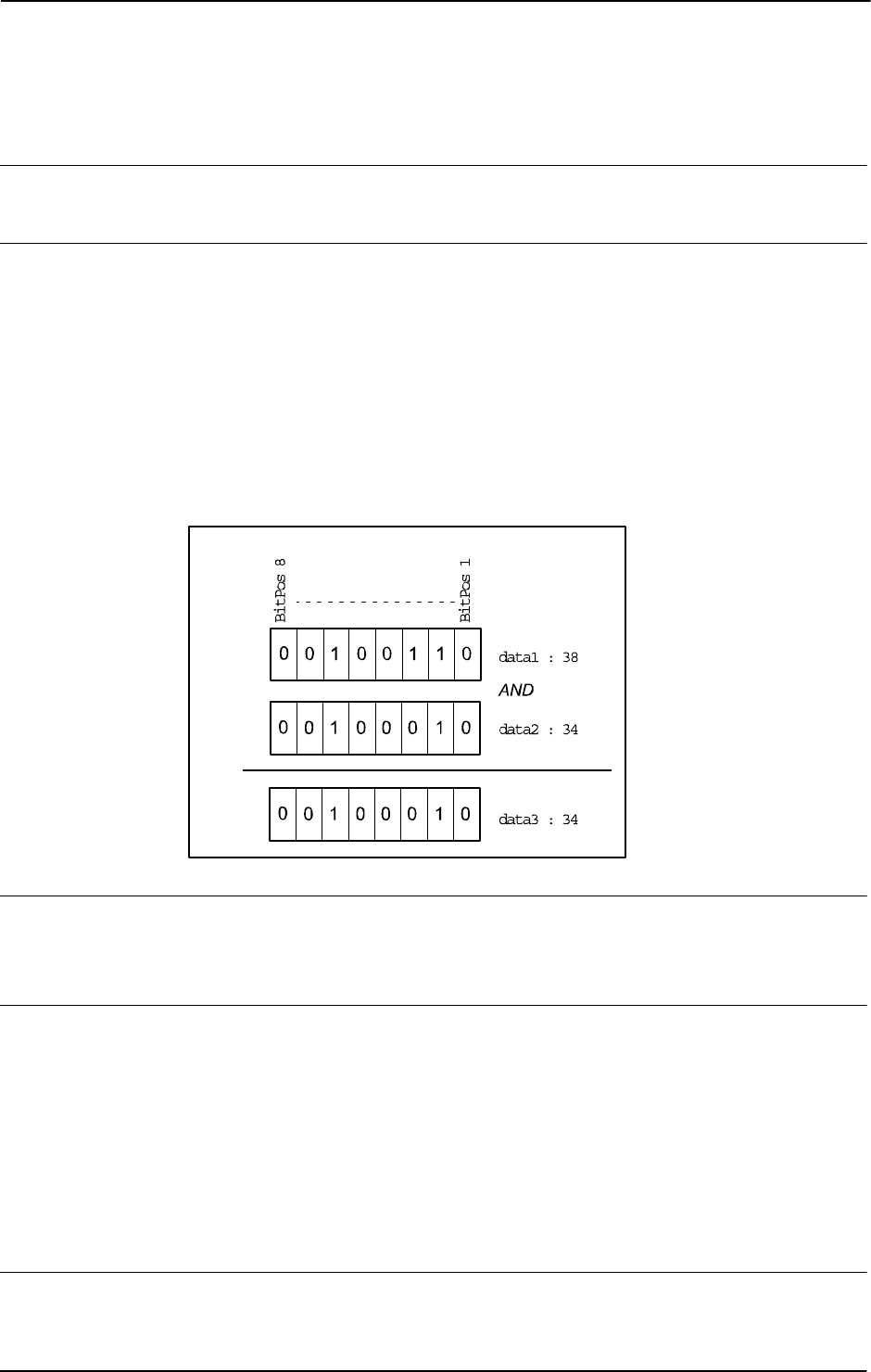
2 Functions
2.8. BitAnd - Logical bitwise AND - operation on byte data
RobotWare - OS
3HAC 16581-1 Revision: J770
© Copyright 2004-2010 ABB. All rights reserved.
2.8. BitAnd - Logical bitwise AND - operation on byte data
Usage
BitAnd is used to execute a logical bitwise AND - operation on data types byte.
Basic examples
Basic examples of the function
BitAnd are illustrated below.
Example 1
VAR byte data1 := 38;
VAR byte data2 := 34;
VAR byte data3;
data3 := BitAnd(data1, data2);
The logical bitwise AND - operation (see figure below) will be executed on the data1 and
data2. The result will be returned to data3 (integer representation).
xx0500002454
Return value
Data type:
byte
The result of the logical bitwise AND - operation in integer representation.
Arguments
BitAnd (BitData1 BitData2)
BitData1
Data type: byte
The bit data 1, in integer representation.
BitData2
Data type: byte
The bit data 2, in integer representation.
Limitations
The range for a data type
byte is 0 - 255.
Continues on next page

2 Functions
2.8. BitAnd - Logical bitwise AND - operation on byte data
RobotWare - OS
7713HAC 16581-1 Revision: J
© Copyright 2004-2010 ABB. All rights reserved.
Syntax
BitAnd’(’
[BitData1 ’:=’] <expression (IN) of byte>’ ,’
[BitData2 ’:=’] <expression (IN) of byte>
’)’
A function with a return value of the data type byte.
Related information
For information about See
Logical bitwise OR - operation on byte data BitOr - Logical bitwise OR - operation on
byte data on page 778
Logical bitwise XOR - operation on byte data BitXOr - Logical bitwise XOR - operation on
byte data on page 782
Logical bitwise NEGATION - operation on byte
data
BitNeg - Logical bitwise NEGATION -
operation on byte data on page 776
Other bit functions Technical reference manual - RAPID
overview, section RAPID summary - Bit
Functions
Continued
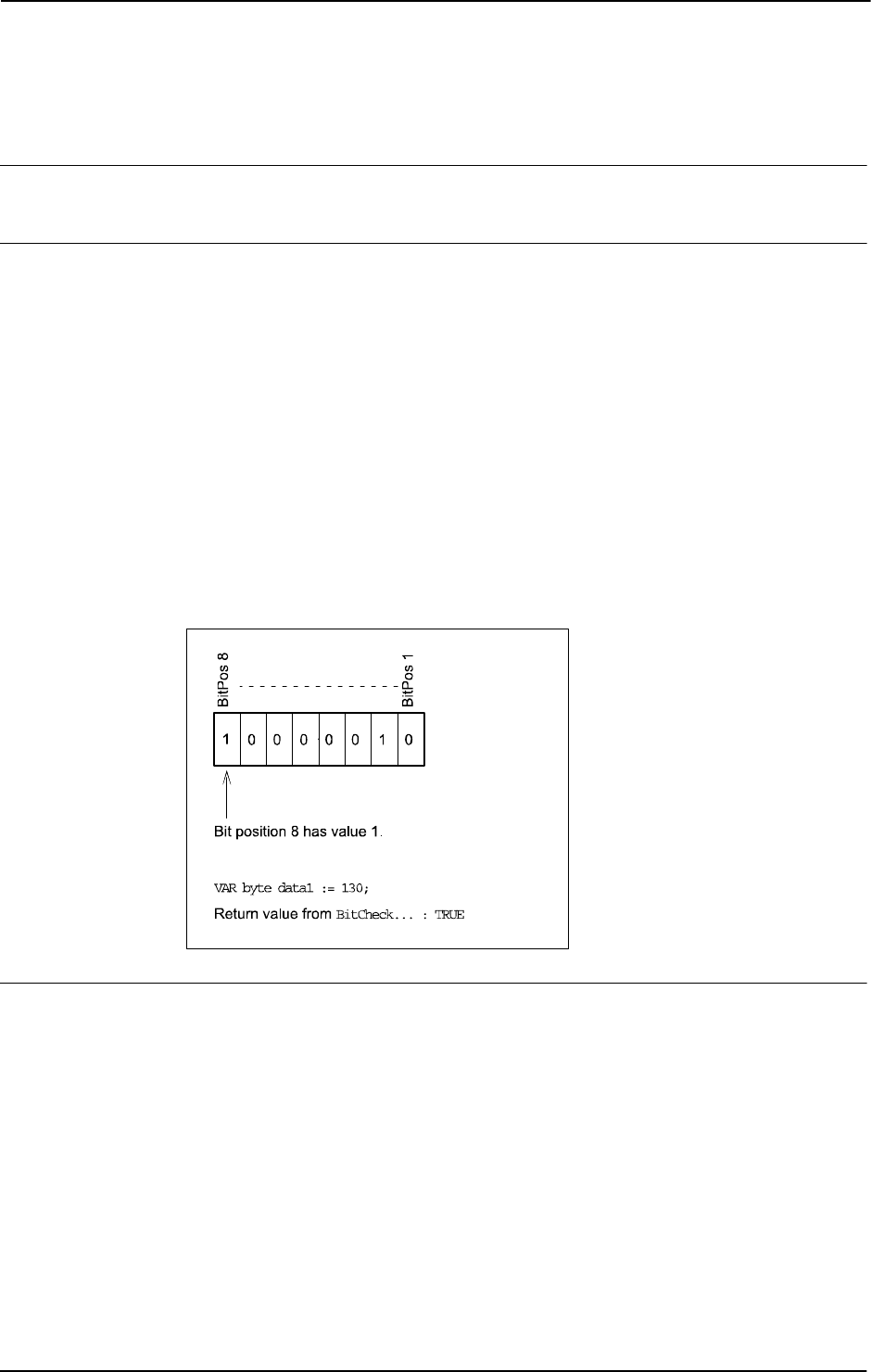
2 Functions
2.9. BitCheck - Check if a specified bit in a byte data is set
RobotWare - OS
3HAC 16581-1 Revision: J772
© Copyright 2004-2010 ABB. All rights reserved.
2.9. BitCheck - Check if a specified bit in a byte data is set
Usage
BitCheck is used to check if a specified bit in a defined byte data is set to 1.
Basic examples
Basic examples of the function
BitCheck are illustrated below.
Example 1
CONST num parity_bit := 8;
VAR byte data1 := 130;
IF BitCheck(data1, parity_bit) = TRUE THEN
...
ELSE
...
ENDIF
Bit number 8 (parity_bit) in the variable data1 will be checked, e.g. if the specified bit
is set to 1 in the variable
data1 then this function will return to TRUE. Bit check of data type
byte is illustrated in the figure below.
xx0500002442
Return value
Data type:
bool
TRUE
if the specified bit is set to 1, FALSE if the specified bit is set to 0.
Continues on next page

2 Functions
2.9. BitCheck - Check if a specified bit in a byte data is set
RobotWare - OS
7733HAC 16581-1 Revision: J
© Copyright 2004-2010 ABB. All rights reserved.
Arguments
BitCheck (BitData BitPos)
BitData
Data type: byte
The bit data, in integer representation, to be checked.
BitPos
Bit Position
Data type:
num
The bit position (1-8) in the BitData to be checked.
Limitations
The range for a data type
byte is 0 - 255 decimal.
The bit position is valid from 1 - 8.
Syntax
BitCheck’(’
[BitData ’:=’] <expression (IN) of byte> ´,’
[BitPos ’:=’] <expression (IN) of num>
’)’
A function with a return value of the data type bool.
Related information
For information about See
Set a specified bit in a byte data BitSet - Set a specified bit in a byte data on page 28
Clear a specified bit in a byte data BitClear - Clear a specified bit in a byte data on page
26
Other bit functions Technical reference manual - RAPID overview,
section RAPID summary - Bit Functions
Continued
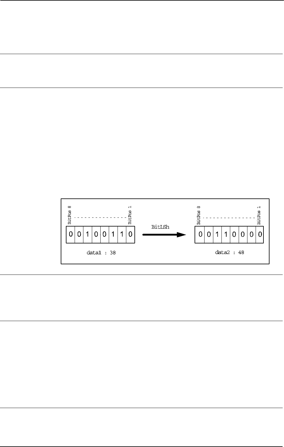
2 Functions
2.10. BitLSh - Logical bitwise LEFT SHIFT - operation on byte
RobotWare - OS
3HAC 16581-1 Revision: J774
© Copyright 2004-2010 ABB. All rights reserved.
2.10. BitLSh - Logical bitwise LEFT SHIFT - operation on byte
Usage
BitLSh (Bit Left Shift) is used to execute a logical bitwise LEFT SHIFT-operation on data
types
byte.
Basic examples
Basic examples of the function
BitLSh are illustrated below.
Example 1
VAR num left_shift := 3;
VAR byte data1 := 38;
VAR byte data2;
data2 := BitLSh(data1, left_shift);
The logical bitwise LEFT SHIFT- operation will be executed on the data1 with 3
(
left_shift) steps of left shift, and the result will be returned to data2 (integer
representation).
The following figure shows logical bitwise LEFT SHIFT-operation.
xx0500002457
Return value
Data type:
byte
The result of the logical bitwise LEFT SHIFT-operation in integer representation.
The right bit cells will be filled up with 0-bits.
Arguments
BitLSh (BitData ShiftSteps)
BitData
Data type: byte
The bit data, in integer representation, to be shifted.
ShiftSteps
Data type: num
Number of the logical shifts (1 - 8) to be executed.
Limitations
The range for a data type
byte is 0 - 255.
The
ShiftSteps argument is valid from 1 - 8 according to one byte.
Continues on next page

2 Functions
2.10. BitLSh - Logical bitwise LEFT SHIFT - operation on byte
RobotWare - OS
7753HAC 16581-1 Revision: J
© Copyright 2004-2010 ABB. All rights reserved.
Syntax
BitLSh’(’
[BitData ’:=’] <expression (IN) of byte>’ ,’
[ShiftSteps’ :=’] <expression (IN) of num>
’)’
A function with a return value of the data type byte.
Related information
For information about See
Logical bitwise RIGHT SHIFT-operation
on byte data
BitRSh - Logical bitwise RIGHT SHIFT -
operation on byte on page 780
Other bit functions Technical reference manual - RAPID overview,
section RAPID summary - Mathematics -
Bit functions
Continued
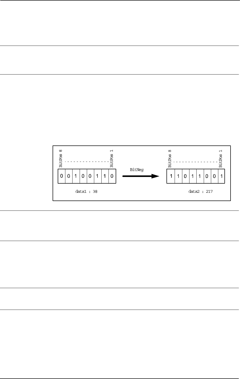
2 Functions
2.11. BitNeg - Logical bitwise NEGATION - operation on byte data
RobotWare - OS
3HAC 16581-1 Revision: J776
© Copyright 2004-2010 ABB. All rights reserved.
2.11. BitNeg - Logical bitwise NEGATION - operation on byte data
Usage
BitNeg (Bit Negation) is used to execute a logical bitwise NEGATION - operation
(one’s complement) on data types
byte.
Basic examples
Basic examples of the function
BitNeg are illustrated below.
Example 1
VAR byte data1 := 38;
VAR byte data2;
data2 := BitNeg(data1);
The logical bitwise NEGATION - operation (see figure below) will be executed on the data1,
and the result will be returned to
data2 (integer representation).
xx0500002456
Return value
Data type:
byte
The result of the logical bitwise NEGATION - operation in integer representation.
Arguments
BitNeg (BitData)
BitData
Data type: byte
The byte data, in integer representation.
Limitations
The range for a data type
byte is 0 - 255.
Syntax
BitNeg’(’
[BitData ’:=’] <expression (IN) of byte>
’)’
A function with a return value of the data type byte.
Continues on next page

2 Functions
2.11. BitNeg - Logical bitwise NEGATION - operation on byte data
RobotWare - OS
7773HAC 16581-1 Revision: J
© Copyright 2004-2010 ABB. All rights reserved.
Related information
For information about See
Logical bitwise AND - operation on byte data BitAnd - Logical bitwise AND - operation on
byte data on page 770
Logical bitwise OR - operation on byte data BitOr - Logical bitwise OR - operation on byte
data on page 778
Logical bitwise XOR - operation on byte data BitXOr - Logical bitwise XOR - operation on
byte data on page 782
Other bit functions Technical reference manual - RAPID
overview, section RAPID summary - Bit
functions
Continued
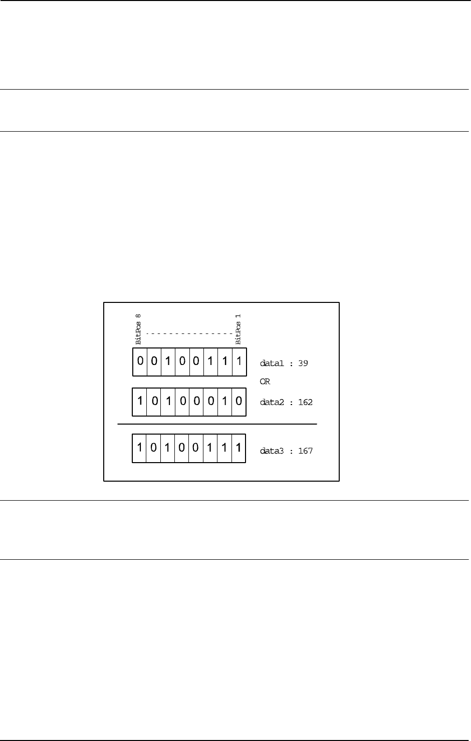
2 Functions
2.12. BitOr - Logical bitwise OR - operation on byte data
RobotWare - OS
3HAC 16581-1 Revision: J778
© Copyright 2004-2010 ABB. All rights reserved.
2.12. BitOr - Logical bitwise OR - operation on byte data
Usage
BitOr (Bit inclusive Or) is used to execute a logical bitwise OR-operation on data types byte.
Basic examples
Basic examples of the function
BitOr are illustrated below.
Example 1
VAR byte data1 := 39;
VAR byte data2 := 162;
VAR byte data3;
data3 := BitOr(data1, data2);
The logical bitwise OR-operation will be executed on the data1 and data2, and the result
will be returned to
data3 (integer representation).
The following figure shows logical bitwise OR-operation.
xx0500002458
Return value
Data type:
byte
The result of the logical bitwise OR-operation in integer representation.
Arguments
BitOr (BitData1 BitData2)
BitData1
Data type: byte
The bit data 1, in integer representation.
BitData2
Data type: byte
The bit data 2, in integer representation.
Continues on next page

2 Functions
2.12. BitOr - Logical bitwise OR - operation on byte data
RobotWare - OS
7793HAC 16581-1 Revision: J
© Copyright 2004-2010 ABB. All rights reserved.
Limitations
The range for a data type
byte is 0 - 255.
Syntax
BitOr’(’
[BitData1 ’:=’] <expression (IN) of byte>’ ,’
[BitData2 ’:=’] <expression (IN) of byte>
’)’
A function with a return value of the data type byte.
Related information
For information about See
Logical bitwise AND - operation on byte
data
BitAnd - Logical bitwise AND - operation on byte
data on page 770
Logical bitwise XOR - operation on byte
data
BitXOr - Logical bitwise XOR - operation on byte
data on page 782
Logical bitwise NEGATION - operation on
byte data
BitNeg - Logical bitwise NEGATION - operation
on byte data on page 776
Other bit functions Technical reference manual - RAPID overview,
section RAPID summary - Mathematics -
Bit functions
Continued

2 Functions
2.13. BitRSh - Logical bitwise RIGHT SHIFT - operation on byte
RobotWare - OS
3HAC 16581-1 Revision: J780
© Copyright 2004-2010 ABB. All rights reserved.
2.13. BitRSh - Logical bitwise RIGHT SHIFT - operation on byte
Usage
BitRSh (Bit Right Shift) is used to execute a logical bitwise RIGHT SHIFT-operation on data
types
byte.
Basic examples
Basic example of the function
BitRSh are illustrated below.
Example 1
VAR num right_shift := 3;
VAR byte data1 := 38;
VAR byte data2;
data2 := BitRSh(data1, right_shift);
The logical bitwise RIGHT SHIFT-operation will be executed on the data1 with 3
(
right_shift) steps of right shift, and the result will be returned to data2
(integer representation)
The following figure shows logical bitwise RIGHT SHIFT-operation.
xx0500002455
Return value
Data type:
byte
The result of the logical bitwise RIGHT SHIFT-operation in integer representation.
The left bit cells will be filled up with 0-bits.
Arguments
BitRSh (BitData ShiftSteps)
BitData
Data type: byte
The bit data, in integer representation, to be shifted.
ShiftSteps
Data type: num
Number of the logical shifts (1 - 8) to be executed.
Limitations
The range for a data type
byte is 0 - 255.
The
ShiftSteps argument is valid from 1 - 8 according to one byte.
Continues on next page

2 Functions
2.13. BitRSh - Logical bitwise RIGHT SHIFT - operation on byte
RobotWare - OS
7813HAC 16581-1 Revision: J
© Copyright 2004-2010 ABB. All rights reserved.
Syntax
BitRSh’(’
[BitData ’:=’] <expression (IN) of byte>’,’
[ShiftSteps’:=’] <expression (IN) of num>
’)’
A function with a return value of the data type byte.
Related information
For information about See
Logical bitwise LEFT SHIFT-operation on
byte data
BitLSh - Logical bitwise LEFT SHIFT - operation
on byte on page 774
Other bit functions Technical reference manual - RAPID overview,
section RAPID summary - Mathematics -
Bit functions
Continued
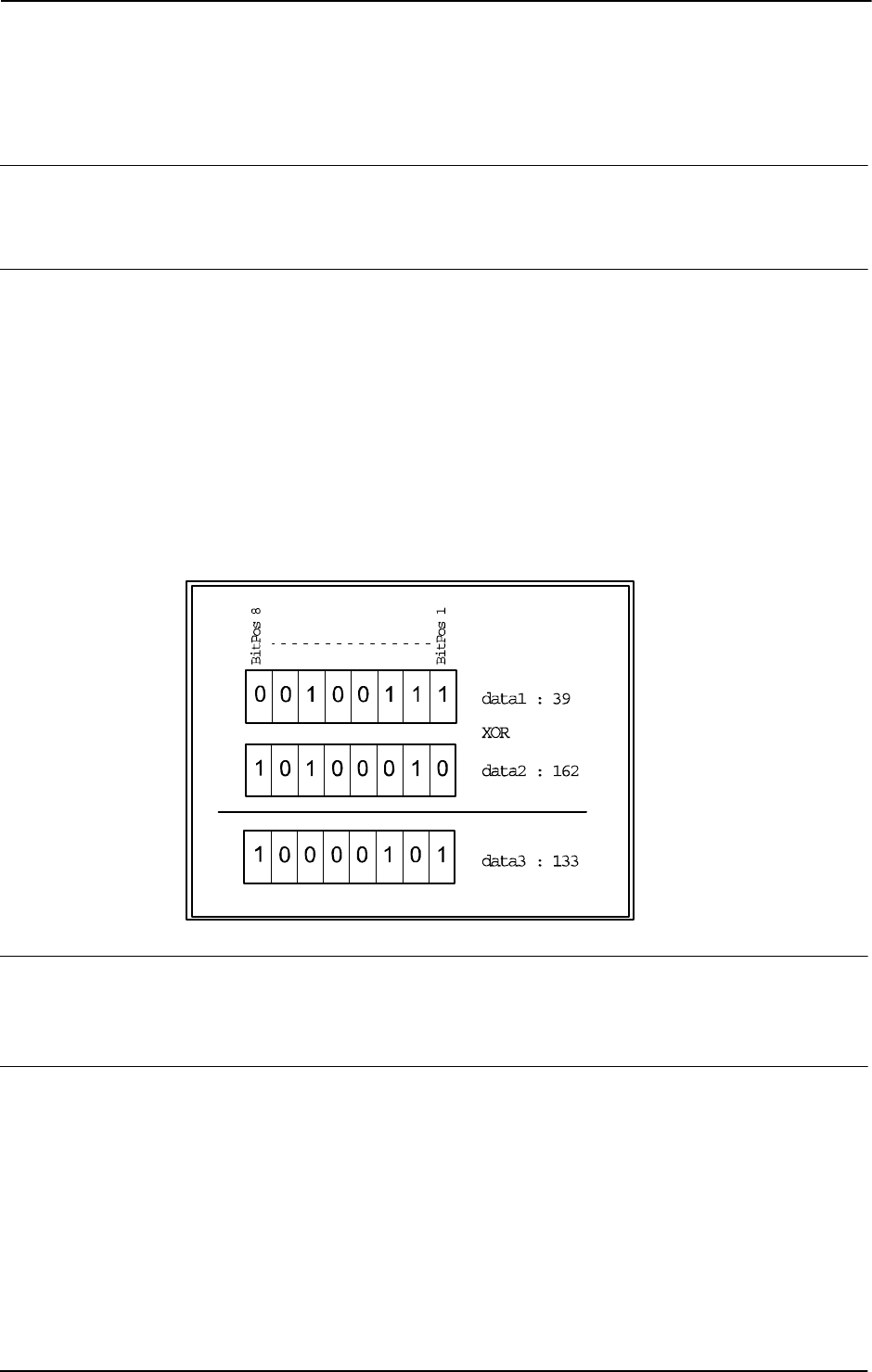
2 Functions
2.14. BitXOr - Logical bitwise XOR - operation on byte data
RobotWare - OS
3HAC 16581-1 Revision: J782
© Copyright 2004-2010 ABB. All rights reserved.
2.14. BitXOr - Logical bitwise XOR - operation on byte data
Usage
BitXOr (Bit eXclusive Or) is used to execute a logical bitwise XOR-operation on data types
byte.
Basic examples
Basic examples of the function
BitXOr are illustrated below.
Example 1
VAR byte data1 := 39;
VAR byte data2 := 162;
VAR byte data3;
data3 := BitXOr(data1, data2);
The logical bitwise XOR -operation will be executed on the data1 and data2, and the result
will be returned to
data3 (integer representation).
The following figure shows logical bitwise XOR-operation.
xx0500002459
Return value
Data type:
byte
The result of the logical bitwise XOR-operation in integer representation.
Arguments
BitXOr (BitData1 BitData2)
BitData1
Data type: byte
The bit data 1, in integer representation.
BitData2
Data type: byte
The bit data 2, in integer representation.
Continues on next page

2 Functions
2.14. BitXOr - Logical bitwise XOR - operation on byte data
RobotWare - OS
7833HAC 16581-1 Revision: J
© Copyright 2004-2010 ABB. All rights reserved.
Limitations
The range for a data type
byte is 0 - 255.
Syntax
BitXOr’(’
[BitData1 ’:=’] <expression (IN) of byte>’ ,’
[BitData2 ’:=’] <expression (IN) of byte>
’)’
A function with a return value of the data type byte.
Related information
For information about See
Logical bitwise AND - operation on byte
data
BitAnd - Logical bitwise AND - operation on byte
data on page 770
Logical bitwise OR - operation on byte
data
BitOr - Logical bitwise OR - operation on byte
data on page 778
Logical bitwise NEGATION - operation on
byte data
BitNeg - Logical bitwise NEGATION - operation
on byte data on page 776
Other bit functions Technical reference manual - RAPID overview,
section RAPID summary - Mathematics -
Bit functions
Continued

2 Functions
2.15. ByteToStr - Converts a byte to a string data
RobotWare - OS
3HAC 16581-1 Revision: J784
© Copyright 2004-2010 ABB. All rights reserved.
2.15. ByteToStr - Converts a byte to a string data
Usage
ByteToStr (Byte To String) is used to convert a byte into a string data with a defined byte
data format.
Basic examples
Basic examples of the function
ByteToStr are illustrated below.
Example 1
VAR string con_data_buffer{5};
VAR byte data1 := 122;
con_data_buffer{1} := ByteToStr(data1);
The content of the array component con_data_buffer{1} will be "122" after the
ByteToStr ... function.
con_data_buffer{2} := ByteToStr(data1\Hex);
The content of the array component con_data_buffer{2} will be "7A" after the
ByteToStr ... function.
con_data_buffer{3} := ByteToStr(data1\Okt);
The content of the array component con_data_buffer{3} will be "172" after the
ByteToStr ... function.
con_data_buffer{4} := ByteToStr(data1\Bin);
The content of the array component con_data_buffer{4} will be "01111010"after the
ByteToStr ... function.
con_data_buffer{5} := ByteToStr(data1\Char);
The content of the array component con_data_buffer{5} will be "z" after the ByteToStr
...
function.
Return value
Data type:
string
The result of the conversion operation with the following format:
(*) If it is a non-writable ASCII character then the return format will be RAPID character
code format (e.g.“ \07” for BEL control character).
Format Characters String length Range
Dec .....: ’0’ -’ 9’ 1-3 "0" - "255"
Hex .....: ’0’ -’ 9’, ’A’ -’F’ 2 "00" - "FF"
Okt ......: ’0’ - ’7’ 3 "000" - "377"
Bin ......: ’0’ - ’1’ 8 "00000000" - "11111111"
Char ....: Any ASCII char (*) 1 One ASCII char
Continues on next page

2 Functions
2.15. ByteToStr - Converts a byte to a string data
RobotWare - OS
7853HAC 16581-1 Revision: J
© Copyright 2004-2010 ABB. All rights reserved.
Arguments
ByteToStr (BitData [\Hex] | [\Okt] | [\Bin] | [\Char])
BitData
Data type: byte
The bit data to be converted.
If the optional switch argument is omitted then the data will be converted in
decimal (Dec)
format.
[\Hex]
Hexadecimal
Data type:
switch
The data will be converted in hexadecimal format.
[\Okt]
Octal
Data type:
switch
The data will be converted in octal format.
[\Bin]
Binary
Data type:
switch
The data will be converted in binary format.
[\Char]
Character
Data type:
switch
The data will be converted in ASCII character format.
Limitations
The range for a data type
byte is 0 to 255 decimal.
Syntax
ByteToStr’(’
[BitData ’:=’] <expression (IN) of byte>
[’\’ Hex ] | [’\’ Okt] | [’\’ Bin] | [’\’ Char]
’)’
A function with a return value of the data type string.
Related information
For information about See
Convert a string to a byte data StrToByte - Converts a string to a byte data on page 1007
Other bit (byte) functions Technical reference manual - RAPID overview, section
RAPID summary - Mathematics - Bit functions
Other string functions Technical reference manual - RAPID overview, section
RAPID summary - String functions
Continued

2 Functions
2.16. CalcJointT - Calculates joint angles from robtarget
RobotWare - OS
3HAC 16581-1 Revision: J786
© Copyright 2004-2010 ABB. All rights reserved.
2.16. CalcJointT - Calculates joint angles from robtarget
Usage
CalcJointT (Calculate Joint Target) is used to calculate joint angles of the robot axes and
external axes from a specified
robtarget data.
The input
robtarget data should be specified in the same coordinate system as specified in
argument for
Tool, WObj, and at execution time active program displacement (ProgDisp)
and external axes offset (
EOffs). The returned jointtarget data is expressed in the
calibration coordinate system.
If MultiMove application type semicoordinated or synchronized coordinated mode with the
coordinated workobject is moved by some mechanical unit located in another program task
then the function
CalcJointT can be used if:
• It is appropriate that the current position of the coordinated work object moved by the
mechanical unit is used in the calculation (current user frame). All other data will be
fetched from the RAPID program.
• The mechanical unit located in another program task is standing still.
• The argument \UseCurWObjPos is used.
Basic examples
Basic examples of the function
CalcJointT are illustrated below.
Example 1
VAR jointtarget jointpos1;
CONST robtarget p1 := [...];
jointpos1 := CalcJointT(p1, tool1 \WObj:=wobj1);
The jointtarget value corresponding to the robtarget value p1 is stored in
jointpos1
. The tool tool1 and work object wobj1 are used for calculating the joint angles
jointpos1.
Example 2
VAR jointtarget jointpos2;
CONST robtarget p2 := [...];
jointpos2 := CalcJointT(\UseCurWObjPos, p2, tool2 \WObj:=orb1);
The jointtarget value corresponding to the robtarget value p2 is stored in
jointpos2
. The tool tool2 and work object orb1 are used for calculating the joint angles
jointpos2. The current position of the standing still manipulator orb1 is not located in the
same program task as the TCP robot but is used for the calculation.
Return value
Data type:
jointtarget
The angles in degrees for the axes of the robot on the arm side.
The values for the external axes, in mm for linear axes, in degrees for rotational axes.
The returned values are always related to the calibration position.
Continues on next page

2 Functions
2.16. CalcJointT - Calculates joint angles from robtarget
RobotWare - OS
7873HAC 16581-1 Revision: J
© Copyright 2004-2010 ABB. All rights reserved.
Arguments
CalcJointT ( [\UseCurWObjPos] Rob_target Tool [\WObj] )
[\UseCurWObjPos]
Data type: switch
Use current position of the coordinated work object moved by the mechanical unit in another
task for the calculation (current user frame). All other data is fetched from the RAPID
program.
Rob_target
Data type: robtarget
The position of the robot and external axes in the outermost coordinate system, related to the
specified tool and work object and at execution time active program displacement
(
ProgDisp) and/or external axes offset (EOffs).
Tool
Data type: tooldata
The tool used for calculation of the robot joint angles.
[\WObj]
Work Object
Data type:
wobjdata
The work object (coordinate system) to which the robot position is related.
If this argument is omitted then the work object
wobj0 is used. This argument must be
specified when using stationary tool, coordinated external axes, or conveyor.
Program execution
The returned
jointtarget is calculated from the input robtarget. If use of the argument
\UseCurWObjPos also the current position of the mechanical unit that controls the user
frame is used. To calculate the robot joint angles, the specified
Tool, WObj (including
coordinated user frame), and the
ProgDisp active at execution time are taken into
consideration. To calculate the external axes position at the execution time, active
EOffs is
taken into consideration.
The calculation always selects the robot configuration according to the specified
configuration data in the input
robtarget data. Instructions ConfL and ConfJ do not affect
this calculation principle. When wrist singularity is used, robot axis 4 will be set to 0 degrees.
If there is any active program displacement (
ProgDisp) and/or external axis offset (EOffs)
at the time the robtarget is stored then the same program displacement and/or external axis
offset must be active when
CalcJointT is executed.
Continued
Continues on next page

2 Functions
2.16. CalcJointT - Calculates joint angles from robtarget
RobotWare - OS
3HAC 16581-1 Revision: J788
© Copyright 2004-2010 ABB. All rights reserved.
Limitation
If a coordinate frame is used then the coordinated unit has to be activated before using
CalcJointT.
The mechanical unit that controls the user frame in the work object must normally be
available in the same program task as the TCP robot which executes
CalcJointT.
Normally
CalcJointT uses robtarget, tooldata, and wobjdata from the RAPID
program to calculate
jointtarget. For coordinated workobjects, the position of the
mechanical unit is given as external axes position in the
robtarget. That is not the case if
the mechanical unit is controlled by another program task (MultiMove system) or the
mechanical unit is not controlled by the control system (Conveyor). For the MultiMove
System but not for the conveyor it is possible to use the argument
\UseCurWObjPos if the
mechanical unit is standing still at the execution time of
CalCJointT.
Error handling
If at least one axis is outside the working area or the limits are exceeded for at least one
coupled joint then the system variable
ERRNO is set to ERR_ROBLIMIT and the execution
continues in the error handler.
If the mechanical unit that controls the work object (user frame) isn’t standing still at
execution time of
CalJointT \UseCurWobjPos then the system variable ERRNO is set to
ERR_WOBJ_MOVING and the execution continues in the error handler.
The error handler can then deal with the situations.
Syntax
CalcJointT’(’
[’\’UseCurWObjPos ’,’]
[Rob_target’ :=’] <expression (IN) of robtarget>‘,’
[Tool ’:=’ ] <persistent (PERS) of tooldata>
[’\’WObj ’:=’ <persistent (PERS) of wobjdata>] ’)’
A function with a return value of the data type jointtarget.
Related information
For information about See
Calculate robtarget from jointtarget CalcRobT - Calculates robtarget from
jointtarget on page 789
Definition of position robtarget - Position data on page 1176
Definition of joint position jointtarget - Joint position data on page 1129
Definition of tools tooldata - Tool data on page 1207
Definition of work objects wobjdata - Work object data on page 1224
Coordinate systems Technical reference manual - RAPID
overview, section Motion and I/O principles -
Coordinate systems
Program displacement coordinate system PDispOn - Activates program displacement
on page 317
External axis offset coordinate system EOffsOn - Activates an offset for external
axes on page 88
Continued

2 Functions
2.17. CalcRobT - Calculates robtarget from jointtarget
RobotWare - OS
7893HAC 16581-1 Revision: J
© Copyright 2004-2010 ABB. All rights reserved.
2.17. CalcRobT - Calculates robtarget from jointtarget
Usage
CalcRobT (Calculate Robot Target) is used to calculate a robtarget data from a given
jointtarget data.
This function returns a
robtarget value with position (x, y, z), orientation (q1 ... q4), robot
axes configuration, and external axes position.
The input
jointtarget data should be specified in the calibration coordinate system.
The returned
robtarget data is expressed in the outermost coordinate system. It takes the
specified tool, work object, and at execution time active program displacement (
ProgDisp)
and external axis offset (
EOffs) into consideration.
Basic examples
Basic examples of the function
CalcRobT are illustrated below.
Example 1
VAR robtarget p1;
CONST jointtarget jointpos1 := [...];
p1 := CalcRobT(jointpos1, tool1 \WObj:=wobj1);
The robtarget value corresponding to the jointtarget value jointpos1 is stored in
p1
. The tool tool1 and work object wobj1 are used for calculating the position of p1.
Return value
Data type:
robtarget
The robot and external axes position is returned in data type robtarget and expressed in the
outermost coordinate system. It takes the specified tool, work object, and at execution time
active program displacement (
ProgDisp) and external axes offset (EOffs) into
consideration.
If there is no active
ProgDisp then the robot position is expressed in the object coordinate
system. If there are no active
EOffs then the external axis position is expressed in the
calibration coordinate system.
Arguments
CalcRobT ( Joint_target Tool [\WObj] )
Joint_target
Data type: jointtarget
The joint position for the robot axes and external axes related to the calibration coordinate
system.
Tool
Data type: tooldata
The tool used for calculation of the robot position.
Continues on next page

2 Functions
2.17. CalcRobT - Calculates robtarget from jointtarget
RobotWare - OS
3HAC 16581-1 Revision: J790
© Copyright 2004-2010 ABB. All rights reserved.
[\WObj]
Work Object
Data type:
wobjdata
The work object (coordinate system) to which the robot position returned by the function is
related.
If this argument is omitted the work object
wobj0 is used. This argument must be specified
when using stationary tool, coordinated external axes, or conveyor.
Program execution
The returned
robtarget is calculated from the input jointtarget. To calculate the
cartesian robot position the specified
Tool, WObj (including coordinated user frame), and at
the execution time active
ProgDisp, are taken into consideration.
To calculate the external axes position, the
EOffs active at execution time is also taken into
consideration.
Limitation
If a coordinate frame is used then the coordinated unit has to be activated before using
CalcRobT. The coordinated unit also has to be situated in the same task as the robot.
Syntax
CalcRobT’(’
[Joint_target ’:=’ ] <expression (IN) of jointtarget>‘,’
[Tool ’:=’ ] <persistent (PERS) of tooldata>
[’\’WObj ’:=’ <persistent (PERS) of wobjdata>] ’)’
A function with a return value of the data type robtarget.
Related information
For information about See
Calculate jointtarget from robtarget CalcJointT - Calculates joint angles from
robtarget on page 786
Definition of position robtarget - Position data on page 1176
Definition of joint position jointtarget - Joint position data on page 1129
Definition of tools tooldata - Tool data on page 1207
Definition of work objects wobjdata - Work object data on page 1224
Coordinate systems Technical reference manual - RAPID overview,
section Motion and I/O Principles - Coordinate
Systems
Program displacement coordinate system PDispOn - Activates program displacement on
page 317
External axes offset coordinate system EOffsOn - Activates an offset for external axes
on page 88
Continued

2 Functions
2.18. CalcRotAxFrameZ - Calculate a rotational axis frame
RobotWare - OS
7913HAC 16581-1 Revision: J
© Copyright 2004-2010 ABB. All rights reserved.
2.18. CalcRotAxFrameZ - Calculate a rotational axis frame
Usage
CalcRotAxFrameZ (Calculate Rotational Axis Frame with positive Z-point) is used to
calculate the user coordinate system of a rotational axis type mechanical unit. This function
is to be used when the master robot and the external axis are located in different RAPID tasks.
If they are in the same task then the function
CalcRotAxisFrame should be used.
Description
The definition of a user frame for a rotational external axis requires that the turntable (or
similar mechanical structure) on the external axis has a marked reference point. Moreover,
the TCP robot’s base frame and TCP must be calibrated. The calibration procedure consists
of a number of positions for the robot’s TCP on the reference point when the turntable is
rotated to different angles. A positioning of the robots TCP in the positive z direction is also
needed. For definition of points for a rotational axis, see the figure below.
xx0500002468
The user coordinate system for the rotational axis has its origin in the center of the turntable.
The z direction coincides with the axis of rotation and the x axis goes through the reference
point.
The figure below shows the user coordinate system for two different positions of the turntable
(turntable seen from above).
xx0500002469
Continues on next page

2 Functions
2.18. CalcRotAxFrameZ - Calculate a rotational axis frame
RobotWare - OS
3HAC 16581-1 Revision: J792
© Copyright 2004-2010 ABB. All rights reserved.
Basic examples
Basic examples of the function
CalcRotAxFrameZ are illustrated below.
Example 1
CONST robtarget pos1 := [...];
CONST robtarget pos2 := [...];
CONST robtarget pos3 := [...];
CONST robtarget pos4 := [...];
CONST robtarget zpos;
VAR robtarget targetlist{10};
VAR num max_err := 0;
VAR num mean_err := 0;
VAR pose resFr:=[...];
PERS tooldata tMyTool:= [...];
! Instructions for creating/ModPos pos1 - pos4 with TCP pointing
at the turntable.
MoveJ pos1, v10, fine, tMyTool;
MoveJ pos2, v10, fine, tMyTool;
MoveJ pos3, v10, fine, tMyTool;
MoveJ pos4, v10, fine, tMyTool;
!Instruction for creating/ModPos zpos with TCP pointing at a point
in positive z direction
MoveJ zpos, v10, fine, tMyTool;
! Add the targets to the array
targetlist{1}:= pos1;
targetlist{2}:= pos2;
targetlist{3}:= pos3;
targetlist{4}:= pos4;
resFr:=CalcRotAxFrameZ(targetlist, 4, zpos, max_err, mean_err);
! Update the system parameters.
IF (max_err < 1.0) AND (mean_err < 0.5) THEN
WriteCfgData "/MOC/SINGLE/STN_1",
"base_frame_pos_x",resFr.trans.x/1000;
WriteCfgData "/MOC/SINGLE/STN_1",
"base_frame_pos_y",resFr.trans.y/1000;
WriteCfgData "/MOC/SINGLE/STN_1",
"base_frame_pos_z",resFr.trans.z/1000;
WriteCfgData "/MOC/SINGLE/STN_1",
"base_frame_orient_u0",resFr.rot.q1;
WriteCfgData "/MOC/SINGLE/STN_1",
"base_frame_orient_u1",resFr.rot.q2;
WriteCfgData "/MOC/SINGLE/STN_1",
"base_frame_orient_u2",resFr.rot.q3;
Continued
Continues on next page
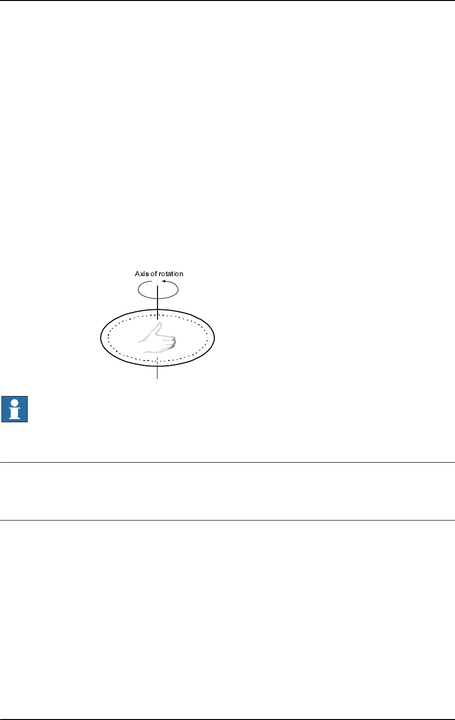
2 Functions
2.18. CalcRotAxFrameZ - Calculate a rotational axis frame
RobotWare - OS
7933HAC 16581-1 Revision: J
© Copyright 2004-2010 ABB. All rights reserved.
WriteCfgData "/MOC/SINGLE/STN_1",
"base_frame_orient_u3",resFr.rot.q4;
TPReadFK reg1,"Warmstart required for calibration to take
effect."
,stEmpty,stEmpty,stEmpty, stEmpty,"OK";
WarmStart;
ENDIF
Four positions, pos1 - pos4, are created/modposed so that the robot’s tool tMyTool points
to the same reference point on the external axis
STN_1 but with different external axis
rotations. Position,
zpos, is created/modposed so that the robot’s tool tMyTool points in the
positive z direction according to the definition of the positive z-direction of an external
rotational mechanical unit. Using the definition of the positive z-direction of an external
rotational mechanical unit, see Description on page 791. The points are then used for
calculating the external axis base frame,
resFr, in relation to the world coordinate system.
Finally, the frame is written to the configuration file and a warmstart is made to let the change
take effect.
xx0500002472
NOTE!
Definition of the positive z-direction of an external rotational mechanical unit:
Let the right hand’s fingers coincide with the positive rotation axis of the rotational axis. The
direction of the thumb then defines the positive z-direction. See the figure above.
Return value
Data type:
pose
The calculated frame.
Arguments
CalcRotAxFrameZ (TargetList TargetsInList PositiveZPoint
MaxErr MeanErr)
TargetList
Data type: robtarget
Array of robtargets holding the positions defined by pointing out the turntable. Minimum
number of robtargets is 4, maximum 10.
TargetsInList
Data type: num
Number of robtargets in an array.
Continued
Continues on next page

2 Functions
2.18. CalcRotAxFrameZ - Calculate a rotational axis frame
RobotWare - OS
3HAC 16581-1 Revision: J794
© Copyright 2004-2010 ABB. All rights reserved.
PositiveZPoint
Data type: robtarget
robtarget
holding the position defined by pointing out a point in the positive z direction.
Using the definition of the positive z-direction of an external rotational mechanical unit, see
Description on page 791.
MaxErr
Maximum Error
Data type:
num
The estimated maximum error in mm.
MeanErr
Mean Error
Data type:
num
The estimated mean error in mm.
Error handling
If the positions don’t have the required relation or are not specified with enough accuracy then
the system variable
ERRNO is set to ERR_FRAME. This error can then be handled in an error
handler.
Syntax
CalcRotAxFrameZ’(’
[TargetList ’:=’] <array {*} (IN) of robtarget>’ ,’
[TargetsInList’ :=’] <expression (IN) of num> ’,’
[PositiveZPoint’ :=’] <expression (IN) of robtarget> ’,’
[MaxErr ’:=’] <variable (VAR) of num> ’,’
[MeanErr ’:=’] <variable (VAR) of num>’)’
A function with a return value of the data type pose.
Related information
For information about See
Mathematical instructions and functions Technical reference manual - RAPID
overview, section RAPID summary -
Mathematics
Continued
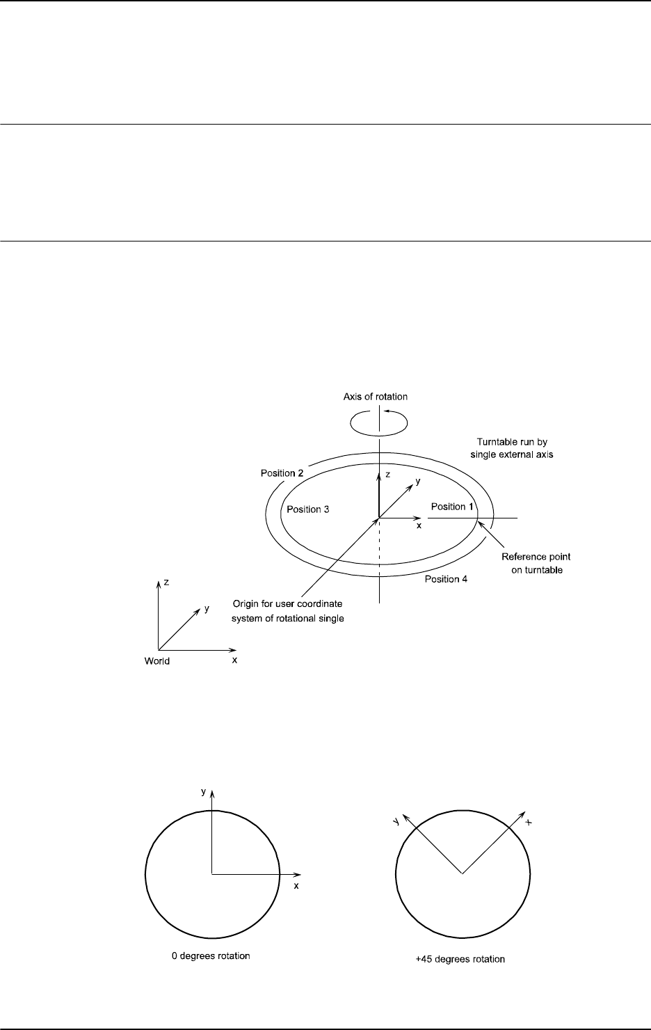
2 Functions
2.19. CalcRotAxisFrame - Calculate a rotational axis frame
RobotWare - OS
7953HAC 16581-1 Revision: J
© Copyright 2004-2010 ABB. All rights reserved.
2.19. CalcRotAxisFrame - Calculate a rotational axis frame
Usage
CalcRotAxisFrame (Calculate Rotational Axis Frame) is used to calculate the user
coordinate system of a rotational axis type mechanical unit. This function is to be used when
the master robot and the external axis are located in the same RAPID task. If they are in
different tasks the function
CalcRotAxFrameZ should be used.
Description
The definition of a user frame for a rotational external axis requires that the turntable (or
similar mechanical structure) on the external axis has a marked reference point. Moreover,
the master robot’s base frame and TCP must be calibrated. The calibration procedure consists
of a number of positions for the robot’s TCP on the reference point when the turntable is
rotated to different angles. Definition of points for a rotational axis is illustrated in the figure
below.
xx0500002468
The user coordinate system for the rotational axis has its origin in the center of the turntable.
The z direction coincides with the axis of rotation and the x axis goes through the reference
point.
The figure below shows the user coordinate system for two different positions of the turntable
(turntable seen from above).
xx0500002469
Continues on next page

2 Functions
2.19. CalcRotAxisFrame - Calculate a rotational axis frame
RobotWare - OS
3HAC 16581-1 Revision: J796
© Copyright 2004-2010 ABB. All rights reserved.
Basic examples
Basic examples of the function
CalcRotAxisFrame are illustrated below.
Example 1
CONST robtarget pos1 := [...];
CONST robtarget pos2 := [...];
CONST robtarget pos3 := [...];
CONST robtarget pos4 := [...];
VAR robtarget targetlist{10};
VAR num max_err := 0;
VAR num mean_err := 0;
VAR pose resFr:=[...];
PERS tooldata tMyTool:= [...];
! Instructions needed for creating/ModPos pos1 - pos4 with TCP
pointing at the turntable.
MoveJ pos1, v10, fine, tMyTool;
MoveJ pos2, v10, fine, tMyTool;
MoveJ pos3, v10, fine, tMyTool;
MoveJ pos4, v10, fine, tMyTool;
! Add the targets to the array
targetlist{1}:= pos1;
targetlist{2}:= pos2;
targetlist{3}:= pos3;
targetlist{4}:= pos4;
resFr:=CalcRotAxisFrame(STN_1 , targetlist, 4, max_err, mean_err);
! Update the system parameters.
IF (max_err < 1.0) AND (mean_err < 0.5) THEN
WriteCfgData "/MOC/SINGLE/STN_1",
"base_frame_pos_x",resFr.trans.x/1000;
WriteCfgData "/MOC/SINGLE/STN_1",
"base_frame_pos_y",resFr.trans.y/1000;
WriteCfgData "/MOC/SINGLE/STN_1",
"base_frame_pos_z",resFr.trans.z/1000;
WriteCfgData "/MOC/SINGLE/STN_1",
"base_frame_orient_u0",resFr.rot.q1;
WriteCfgData "/MOC/SINGLE/STN_1",
"base_frame_orient_u1",resFr.rot.q2;
WriteCfgData "/MOC/SINGLE/STN_1",
"base_frame_orient_u2",resFr.rot.q3;
WriteCfgData "/MOC/SINGLE/STN_1",
"base_frame_orient_u3",resFr.rot.q4;
TPReadFK reg1,"Warmstart required for calibration to take
effect.",stEmpty,stEmpty,stEmpty,stEmpty,"OK";
WarmStart;
ENDIF
Continued
Continues on next page

2 Functions
2.19. CalcRotAxisFrame - Calculate a rotational axis frame
RobotWare - OS
7973HAC 16581-1 Revision: J
© Copyright 2004-2010 ABB. All rights reserved.
Four positions, pos1 - pos4, are created/modposed so that the robot’s tool tMyTool points
to the same reference point on the external axis
STN_1 but with different external axis
rotations. The points are then used for calculating the external axis base frame,
resFr, in
relation to the world coordinate system. Finally, the frame is written to the configuration file
and a warmstart is made to let the change take effect.
Return value
Data type:
pose
The calculated frame.
Arguments
CalcRotAxisFrame (MechUnit [\AxisNo] TargetList TargetsInList
MaxErr MeanErr)
MechUnit
Mechanical Unit
Data type:
mecunit
Name of the mechanical unit to be calibrated.
[\AxisNo]
Data type: num
Optional argument defining the axis number for which a frame should be determined. Default
value is 1 applying to single rotational axis. For mechanical units with several axes, the axis
number should be supplied with this argument.
TargetList
Data type: robtarget
Array of robtargets holding the positions defined by pointing out the turntable. Minimum
number of robtargets is 4, maximum is 10.
TargetsInList
Data type: num
Number of robtargets in an array.
MaxErr
Maximum Error
Data type:
num
The estimated maximum error in mm.
MeanErr
Mean Error
Data type:
num
The estimated mean error in mm.
Error handling
If the positions don’t have the required relation or are not specified with enough accuracy then
the system variable
ERRNO is set to ERR_FRAME. This error can then be handled in an error
handler.
Continued
Continues on next page

2 Functions
2.19. CalcRotAxisFrame - Calculate a rotational axis frame
RobotWare - OS
3HAC 16581-1 Revision: J798
© Copyright 2004-2010 ABB. All rights reserved.
Syntax
CalcRotAxisFrame’(’
[MechUnit ’:=’] <variable (VAR) of mecunit>
[\AxisNo ’:=’ <expression (IN) of num> ]’,’
[TargetList’:=’] <array {*} (IN) of robtarget> ’,’
[TargetsInList’:=’] <expression (IN) of num> ’,’
[MaxErr ’:=’] <variable (VAR) of num> ’,’
[MeanErr ’:=’] <variable (VAR) of num>’)’
A function with a return value of the data type pose.
Related information
For information about See
Mathematical instructions and functions Technical reference manual - RAPID
overview, section RAPID summary -
Mathematics
Continued

2 Functions
2.20. CDate - Reads the current date as a string
RobotWare-OS
7993HAC 16581-1 Revision: J
© Copyright 2004-2010 ABB. All rights reserved.
2.20. CDate - Reads the current date as a string
Usage
CDate (Current Date) is used to read the current system date.
This function can be used to present the current date to the operator on the FlexPendant
display or to paste the current date into a text file that the program writes to.
Basic examples
Basic examples of the function
CDate are illustrated below.
See also on page 799.
Example 1
VAR string date;
date := CDate();
The current date is stored in the variable date.
Return value
Data type:
string
The current date in a string.
The standard date format is “year-month-day”, e.g. ”1998-01-29”.
More examples
More examples of the function
CDate are illustrated below.
Example 1
VAR string date;
date := CDate();
TPWrite "The current date is: "+date;
Write logfile, date;
The current date is written to the FlexPendant display and into a text file.
Syntax
CDate ’(’ ’)’
A function with a return value of the type string.
Related information
For information about See
Time instructions Technical reference manual - RAPID overview,
section RAPID summary - System & time
Setting the system clock Operating manual - IRC5 with FlexPendant, section
Changing FlexPendant settings

2 Functions
2.21. CJointT - Reads the current joint angles
RobotWare - OS
3HAC 16581-1 Revision: J800
© Copyright 2004-2010 ABB. All rights reserved.
2.21. CJointT - Reads the current joint angles
Usage
CJointT (Current Joint Target) is used to read the current angles of the robot axes and
external axes.
Basic examples
Basic examples of the function
CJointT are illustrated below.
See also More examples on page 801.
Example 1
VAR jointtarget joints;
joints := CJointT();
The current angles of the axes for a robot and external axes are stored in joints.
Return value
Data type:
jointtarget
The current angles in degrees for the axes of the robot on the arm side.
The current values for the external axes, in mm for linear axes, in degrees for rotational axes.
The returned values are related to the calibration position.
Arguments
CJointT ([\TaskRef]|[\TaskName])
[\TaskRef]
Task Reference
Data type:
taskid
The program task identity from which the jointtarget should be read.
For all program tasks in the system, predefined variables of the data type
taskid will be
available. The variable identity will be "taskname"+"Id", e.g. for the
T_ROB1 task, and the
variable identity will be
T_ROB1Id.
[\TaskName]
Data type: string
The program task name from which the jointtarget should be read.
If none of the arguments
\TaskRef or \TaskName are specified then the current task is used.
Continues on next page

2 Functions
2.21. CJointT - Reads the current joint angles
RobotWare - OS
8013HAC 16581-1 Revision: J
© Copyright 2004-2010 ABB. All rights reserved.
More examples
More examples of the function
CJointT are illustrated below.
Example 1
! In task T_ROB1
VAR jointtarget joints;
joints := CJointT(\TaskRef:=T_ROB2Id);
The current position of the robot and external axes in task T_ROB2 are stored in joints in
task
T_ROB1.
Note that the robot in task
T_ROB2 may be moving when the position is read. To make sure
the robot stands still, a stop point
fine in the preceding movement instruction in task T_ROB2
could be programmed and instruction
WaitSyncTask could be used to synchronize the
instructions in task
T_ROB1.
Example 2
! In task T_ROB1
VAR jointtarget joints;
joints := CJointT(\TaskName:="T_ROB2");
The same effect as Example 1 above.
Error handling
If argument
\TaskRef or \TaskName specify some non-motion task then the system ERRNO
is set to
ERR_NOT_MOVETASK. This error can be handled in the error handler.
But no error will be generated if argument
\TaskRef or \TaskName specifies the non-
motion task that executes this function
CJointT (reference to my own non-motion task). The
position will then be fetched from the connected motion task.
Syntax
CJointT’(’
[’\’ TaskRef’ :=’ <variable (VAR) of taskid>]
|[’\’ TaskName’ :=’ <expression (IN) of string>]’)’
A function with a return value of the data type jointtarget.
Related information
For information about See
Definition of joint jointtarget - Joint position data on page 1129
Reading the current motor angle ReadMotor - Reads the current motor angles on
page 947
Continued

2 Functions
2.22. ClkRead - Reads a clock used for timing
RobotWare-OS
3HAC 16581-1 Revision: J802
© Copyright 2004-2010 ABB. All rights reserved.
2.22. ClkRead - Reads a clock used for timing
Usage
ClkRead is used to read a clock that functions as a stop-watch used for timing.
Basic examples
Basic examples of the instruction
ClkRead are illustrated below.
Example 1
reg1:=ClkRead(clock1);
The clock clock1 is read and the time in seconds is stored in the variable reg1.
Return value
Data type:
num
The time in seconds stored in the clock. Resolution 0.01 seconds.
Argument
ClkRead (Clock)
Clock
Data type: clock
The name of the clock to read.
Program execution
A clock can be read when it is stopped or running.
Once a clock is read it can be read again, started again, stopped, or reset.
Error handling
If the clock runs for 4,294,967 seconds (49 days 17 hours 2 minutes 47 seconds) then it
becomes overflowed and the system variable ERRNO is set to ERR_OVERFLOW.
The error can be handled in the error handler.
Syntax
ClkRead ’(’
[ Clock ’:=’ ] < variable (VAR) of clock > ’)’
A function with a return value of the type num.
Related information
For information about See
Clock instructions Technical reference manual - RAPID overview,
section RAPID Summary - System & Time
More examples ClkStart - Starts a clock used for timing on page 52

2 Functions
2.23. CorrRead - Reads the current total offsets
Path Offset
8033HAC 16581-1 Revision: J
© Copyright 2004-2010 ABB. All rights reserved.
2.23. CorrRead - Reads the current total offsets
Usage
CorrRead is used to read the total corrections delivered by all connected correction
generators.
CorrRead can be used to:
• find out how much the current path differs from the original path.
• take actions to reduce the difference.
Basic examples
Basic examples of the function
CorrRead are illustrated below.
See also More examples on page 803.
Example 1
VAR pos offset;
...
offset := CorrRead();
The current offsets delivered by all connected correction generators are available in the
variable offset.
Return value
Data type:
pos
The total absolute offsets delivered from all connected correction generators so far.
More examples
For more examples of the function
CorrRead, see instruction CorrCon.
Syntax
CorrRead’ (’ ’)’
A function with a return value of the data type pos.
Related information
For information about See
Connects to a correction generator CorrCon - Connects to a correction generator
on page 71
Disconnects from a correction generator CorrDiscon - Disconnects from a correction
generator on page 76
Writes to a correction generator CorrWrite - Writes to a correction generator on
page 77
Removes all correction generators CorrClear - Removes all correction generators
on page 70
Correction descriptor corrdescr - Correction generator descriptor on
page 1099

2 Functions
2.24. Cos - Calculates the cosine value
RobotWare - OS
3HAC 16581-1 Revision: J804
© Copyright 2004-2010 ABB. All rights reserved.
2.24. Cos - Calculates the cosine value
Usage
Cos (Cosine) is used to calculate the cosine value from an angle value.
Basic examples
Basic examples of the function
Cos are illustrated below.
Example 1
VAR num angle;
VAR num value;
...
...
value := Cos(angle);
value
will get the cosine value of angle.
Return value
Data type:
num
The cosine value, range = [-1, 1] .
Arguments
Cos (Angle)
Angle
Data type: num
The angle value, expressed in degrees.
Syntax
Cos’(’
[Angle ’:=’] <expression (IN) of num>
’)’
A function with a return value of the data type num.
Related information
For information about See
Mathematical instructions and functions Technical reference manual - RAPID overview,
section RAPID summary - Mathematics

2 Functions
2.25. CPos - Reads the current position (pos) data
RobotWare - OS
8053HAC 16581-1 Revision: J
© Copyright 2004-2010 ABB. All rights reserved.
2.25. CPos - Reads the current position (pos) data
Usage
CPos (Current Position) is used to read the current position of the robot.
This function returns the x, y, and z values of the robot TCP as data of type pos. If the
complete robot position (
robtarget) is to be read then use the function CRobT instead.
Basic examples
Basic examples of the function
CPos are illustrated below.
See also More examples on page 806.
VAR pos pos1;
MoveL *, v500, fine \Inpos := inpos50, tool1;
pos1 := CPos(\Tool:=tool1 \WObj:=wobj0);
The current position of the robot TCP is stored in variable pos1. The tool tool1 and work
object
wobj0 are used for calculating the position.
Note that the robot is standing still before the position is read and calculated. This is achieved
by using the stop point
fine within position accuracy inpos50 in the preceding movement
instruction.
Return value
Data type:
pos
The current position (pos) of the robot with x, y, and z in the outermost coordinate system,
taking the specified tool, work object, and active ProgDisp coordinate system into
consideration.
Arguments
CPos ([\Tool] [\WObj])
[\Tool]
Data type: tooldata
The tool used for calculation of the current robot position.
If this argument is omitted then the current active tool is used.
[\WObj]
Work Object
Data type:
wobjdata
The work object (coordinate system) to which the current robot position returned by the
function is related.
If this argument is omitted then the current active work object is used.
WARNING!
It is advised to always specify the arguments
\Tool and \WObj during programming. The
function will then always return the wanted position even if another tool or work object are
activated.
Continues on next page

2 Functions
2.25. CPos - Reads the current position (pos) data
RobotWare - OS
3HAC 16581-1 Revision: J806
© Copyright 2004-2010 ABB. All rights reserved.
Program execution
The coordinates returned represent the TCP position in the ProgDisp coordinate system.
More examples
More examples of the function
CPos are illustrated below.
VAR pos pos2;
VAR pos pos3;
VAR pos pos4;
pos2 := CPos(\Tool:=grip3 \WObj:=fixture);
...
pos3 := CPos(\Tool:=grip3 \WObj:=fixture);
pos4 := pos3-pos2;
The x, y, and z position of the robot is captured at two places within the program using the
CPos function. The tool grip3 and work object fixture are used for calculating the
position. The x, y, and z distances travelled between these positions are then calculated and
stored in variable
pos4.
Syntax
CPos ’(’
[’\’Tool ’:=’ <persistent (PERS) of tooldata>]
[’\’WObj ’:=’ <persistent (PERS) of wobjdata>] ’)’
A function with a return value of the data type pos.
Related information
For information about See
Definition of position pos - Positions (only X, Y and Z) on page 1160
Definition of tools tooldata - Tool data on page 1207
Definition of work objects wobjdata - Work object data on page 1224
ProgDisp coordinate system PDispOn - Activates program displacement on page 317
Coordinate systems Technical reference manual - RAPID overview, section
Motion and I/O Principles - Coordinate systems
Reading the current robtarget CRobT - Reads the current position (robtarget) data on
page 807
Continued

2 Functions
2.26. CRobT - Reads the current position (robtarget) data
RobotWare - OS
8073HAC 16581-1 Revision: J
© Copyright 2004-2010 ABB. All rights reserved.
2.26. CRobT - Reads the current position (robtarget) data
Usage
CRobT(Current Robot Target) is used to read the current position of a robot and external axes.
This function returns a
robtarget value with position (x, y, z), orientation (q1 ... q4), robot
axes configuration, and external axes position. If only the x, y, and z values of the robot TCP
(
pos) are to be read then use the function CPos instead.
Basic examples
Basic examples of the function
CRobT are illustrated below.
See also More examples on page 808.
Example 1
VAR robtarget p1;
MoveL *, v500, fine \Inpos := inpos50, tool1;
p1 := CRobT(\Tool:=tool1 \WObj:=wobj0);
The current position of the robot and external axes is stored in p1. The tool tool1 and work
object
wobj0 are used for calculating the position.
Note that the robot is standing still before the position is read and calculated. This is achieved
by using the stop point
fine within position accuracy inpos50 in the preceding movement
instruction.
Return value
Data type:
robtarget
The current position of a robot and external axes in the outermost coordinate system, taking
the specified tool, work object, and active
ProgDisp/ExtOffs coordinate system into
consideration.
Arguments
CRobT ([\TaskRef]|[\TaskName] [\Tool] [\WObj])
[\TaskRef]
Task Reference
Data type:
taskid
The program task identity from which the robtarget should be read.
For all program tasks in the system, predefined variables of the data type
taskid will be
available. The variable identity will be "taskname"+"Id", e.g. for the
T_ROB1 task the variable
identity will be
T_ROB1Id.
[\TaskName]
Data type: string
The program task name from which the robtarget should be read.
If none of the arguments
\TaskRef or \TaskName are specified then the current task is used.
Continues on next page

2 Functions
2.26. CRobT - Reads the current position (robtarget) data
RobotWare - OS
3HAC 16581-1 Revision: J808
© Copyright 2004-2010 ABB. All rights reserved.
[\Tool]
Data type: tooldata
The persistent variable for the tool used to calculate the current robot position.
If this argument is omitted then the current active tool is used.
[\WObj]
Work Object
Data type:
wobjdata
The persistent variable for the work object (coordinate system) to which the current robot
position returned by the function is related.
If this argument is omitted then the current active work object is used.
WARNING!
It is advised to always specify the arguments
\Tool and \WObj during programming. The
function will then always return the wanted position even if another tool or work object are
activated.
Program execution
The coordinates returned represent the TCP position in the
ProgDisp coordinate system.
External axes are represented in the
ExtOffs coordinate system.
If one of the arguments
\TaskRef or \TaskName are used but arguments Tool and WObj are
not used then the current tool and work object in the specified task will be used.
More examples
More examples of the function
CRobT are illustrated below.
Example 1
VAR robtarget p2;
p2 := ORobT( CRobT(\Tool:=grip3 \WObj:=fixture) );
The current position in the object coordinate system (without any ProgDisp or ExtOffs) of
the robot and external axes is stored in
p2. The tool grip3 and work object fixture are used
for calculating the position.
Example 2
! In task T_ROB1
VAR robtarget p3;
p3 := CRobT(\TaskRef:=T_ROB2Id \Tool:=tool1 \WObj:=wobj0);
The current position of the robot and external axes in task T_ROB2 are stored in p3 in task
T_ROB1. The tool tool1 and work object wobj0 are used for calculating the position.
Note that the robot in task
T_ROB2 may be moving when the position is read and calculated.
To make sure the robot stands still, a stop point
fine in the preceding movement instruction
in task
T_ROB2 could be programmed and instruction WaitSyncTask could be used to
synchronize the instructions in task
T_ROB1.
Continued
Continues on next page

2 Functions
2.26. CRobT - Reads the current position (robtarget) data
RobotWare - OS
8093HAC 16581-1 Revision: J
© Copyright 2004-2010 ABB. All rights reserved.
Example 3
! In task T_ROB1
VAR robtarget p4;
p4 := CRobT(\TaskName:="T_ROB2");
The current position of the robot and external axes in task T_ROB2 are stored in p4 in task
T_ROB1. The current tool and work object in task T_ROB2 are used for calculating the
position.
Error handling
If argument
\TaskRef or \TaskName specify some non-motion task then the system ERRNO
is set to
ERR_NOT_MOVETASK. This error can be handled in the error handler.
But no error will be generated if the arguments
\TaskRef or \TaskName specify the non-
motion task that executes this function
CRobT (reference to my own non-motion task). The
position will then be fetched from the connected motion task.
Syntax
CRobT’(’
[’\’ TaskRef ’:=’ <variable (VAR) of taskid>]
|[’\’ TaskName’ :=’ <expression (IN) of string>]
[’\’Tool ’:=’ <persistent (PERS) of tooldata>]
[’\’WObj ’:=’ <persistent (PERS) of wobjdata>] ’)’
A function with a return value of the data type robtarget.
Related information
For information about See
Definition of position robtarget - Position data on page 1176
Definition of tools tooldata - Tool data on page 1207
Definition of work objects wobjdata - Work object data on page 1224
Coordinate systems Technical reference manual - RAPID overview,
section Motion and I/O principles - Coordinate
systems
ProgDisp coordinate system PDispOn - Activates program displacement on
page 317
ExtOffs coordinate system EOffsOn - Activates an offset for external axes on
page 88
Reading the current pos (x, y, z only) CPos - Reads the current position (pos) data on
page 805
Continued

2 Functions
2.27. CSpeedOverride - Reads the current override speed
RobotWare - OS
3HAC 16581-1 Revision: J810
© Copyright 2004-2010 ABB. All rights reserved.
2.27. CSpeedOverride - Reads the current override speed
Usage
CSpeedOverride is used to read the speed override set by the operator from the
FlexPendant. The return value is displayed as a percentage where 100% corresponds to the
programmed speed.
In applications with instruction
SpeedRefresh, this function can also be used to read current
speed override value for this or connected motion program tasks.
Note! Must not be mixed up with the argument
Override in the RAPID instruction VelSet.
Basic examples
Basic examples of the function
CSpeedOverride are illustrated below.
Example 1
VAR num myspeed;
myspeed := CSpeedOverride();
The current override speed will be stored in the variable myspeed. E.g. if the value is 100
then this is equivalent to 100%.
Return value
Data type:
num
The override speed value in percent of the programmed speed. This will be a numeric value
in the range of 0 - 100.
Arguments
CSpeedOverride ( [\CTask] )
[\CTask
]
Data type: switch
Get current speed override value for this or connected motion program task. Used together
with the instruction
SpeedRefresh.
If this argument is not used then the function returns current speed override for the whole
system (all motion program tasks). Meaning the manual speed override, set from Teach
Pendant.
Syntax
CSpeedOverride’(’
[’\’ CTask ] ’)’
A function with a return value of the data type num.
Continues on next page

2 Functions
2.27. CSpeedOverride - Reads the current override speed
RobotWare - OS
8113HAC 16581-1 Revision: J
© Copyright 2004-2010 ABB. All rights reserved.
Related information
For information about See
Changing the Override Speed Operating manual - IRC5 with FlexPendant, section
Programming and Testing Production Running -
Quickset menu, Speed
Update speed override from RAPID SpeedRefresh - Update speed override for ongoing
movement on page 476
Continued

2 Functions
2.28. CTime - Reads the current time as a string
RobotWare-OS
3HAC 16581-1 Revision: J812
© Copyright 2004-2010 ABB. All rights reserved.
2.28. CTime - Reads the current time as a string
Usage
CTime is used to read the current system time.
This function can be used to present the current time to the operator on the FlexPendant
display or to paste the current time into a text file that the program writes to.
Basic examples
Basic examples of the function
CTime are illustrated below.
Example 1
VAR string time;
time := CTime();
The current time is stored in the variable time.
Return value
Data type:
string
The current time in a string.
The standard time format is "hours:minutes:seconds", e.g. "18:20:46".
More example
More examples of the function
CTime are illustrated below.
Example 1
VAR string time;
time := CTime();
TPWrite "The current time is: "+time;
Write logfile, time;
The current time is written to the FlexPendant display and written into a text file.
Syntax
CTime ’(’ ’)’
A function with a return value of the type string.
Related information
For information about See
Time and date instructions Technical reference manual - RAPID overview,
section RAPID summary - System & Time
Setting the system clock Operating manual - IRC5 with FlexPendant, section
Changing FlexPendant settings

2 Functions
2.29. CTool - Reads the current tool data
RobotWare - OS
8133HAC 16581-1 Revision: J
© Copyright 2004-2010 ABB. All rights reserved.
2.29. CTool - Reads the current tool data
Usage
CTool (Current Tool) is used to read the data of the current tool.
Basic examples
Basic examples of the function
CTool are illustrated below:
Example 1
PERS tooldata temp_tool:= [ TRUE, [ [0, 0, 0], [1, 0, 0 ,0] ],
[0.001, [0, 0, 0.001], [1, 0, 0, 0], 0, 0, 0] ];
temp_tool := CTool();
The value of the current tool is stored in the variable temp_tool.
Return value
Data type:
tooldata
This function returns a tooldata value holding the value of the current tool, i.e. the tool last
used in a movement instruction.
The value returned represents the TCP position and orientation in the wrist centre coordinate
system. See
tooldata.
Syntax
CTool’(’’)’
A function with a return value of the data type tooldata.
Related information
For information about See
Definition of tools tooldata - Tool data on page 1207
Coordinate systems Technical reference manual - RAPID overview,
section Motion and I/O principles - Coordinate
Systems

2 Functions
2.30. CWObj - Reads the current work object data
RobotWare - OS
3HAC 16581-1 Revision: J814
© Copyright 2004-2010 ABB. All rights reserved.
2.30. CWObj - Reads the current work object data
Usage
CWObj (Current Work Object) is used to read the data of the current work object.
Basic examples
Basic examples of the function
CWObj are illustrated below.
Example 1
PERS wobjdata temp_wobj:= [FALSE, TRUE, "", [[0,0,0], [1,0,0,0]],
[[0,0,0], [1,0,0,0]]];
temp_wobj := CWObj();
The value of the current work object is stored in the variable temp_wobj.
Return value
Data type:
wobjdata
This function returns a wobjdata value holding the value of the current work object, i.e. the
work object last used in a movement instruction.
The value returned represents the work object position and orientation in the world coordinate
system. See
wobjdata.
Syntax
CWObj’(’’)’
A function with a return value of the data type wobjdata.
Related information
For information about See
Definition of work objects wobjdata - Work object data on page 1224
Coordinate systems Technical reference manual - RAPID overview,
section Motion and I/O Principles - Coordinate
Systems

2 Functions
2.31. DecToHex - Convert from decimal to hexadecimal
RobotWare - OS
8153HAC 16581-1 Revision: J
© Copyright 2004-2010 ABB. All rights reserved.
2.31. DecToHex - Convert from decimal to hexadecimal
Usage
DecToHex is used to convert a number specified in a readable string in the base 10 to the
base 16.
The resulting string is constructed from the character set [0-9,A-F,a-f].
This routine handle numbers from 0 up to 9223372036854775807dec or
7FFFFFFFFFFFFFFF hex.
Basic examples
Basic examples of the function
DecToHex are illustrated below.
Example 1
VAR string str;
str := DecToHex("99999999");
The variable str is given the value "5F5E0FF".
Return value
Data type:
string
The string converted to a hexadecimal representation of the given number in the inparameter
string.
Arguments
DecToHex ( Str )
Str
String
Data type:
string
The string to convert.
Syntax
DecToHex’(’
[ Str ’:=’ ] <expression (IN) of string>
’)’
A function with a return value of the data type string.
Related information
For information about See
String functions Technical reference manual - RAPID overview,
section RAPID summary - String functions
Definition of string string - Strings on page 1195
String values Technical reference manual - RAPID overview,
section Basic characteristics - Basic elements
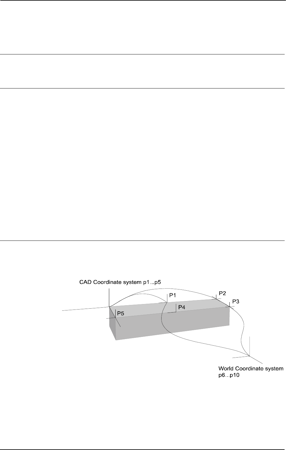
2 Functions
2.32. DefAccFrame - Define an accurate frame
RobotWare - OS
3HAC 16581-1 Revision: J816
© Copyright 2004-2010 ABB. All rights reserved.
2.32. DefAccFrame - Define an accurate frame
Usage
DefAccFrame (Define Accurate Frame) is used to define a framed from three to ten original
positions and the same number of displaced positions.
Description
A frame can be defined when a set of targets are known at two different locations. Thus, the
same physical positions are used but expressed differently.
Consider it in two different approaches:
1. The same physical positions are expressed in relation to different coordinate systems.
For example, a number of positions are retrieved from a CAD drawing, thus the
positions are expressed in a CAD local coordinate system. The same positions are then
expressed in robot world coordinate system. From these two sets of positions the
frame between CAD coordinate system and robot world coordinate system is
calculated.
2. A number of positions are related to an object in an original position. After a
displacement of the object, the positions are determined again (often searched for).
From these two sets of positions (old positions, new positions) the displacement frame
is calculated.
Three targets are enough to define a frame, but to improve accuracy several points should be
used.
Basic examples
Basic examples of the function
DefAccFrame are illustrated below.
Example 1
xx0500002179
CONST robtarget p1 := [...];
CONST robtarget p2 := [...];
CONST robtarget p3 := [...];
CONST robtarget p4 := [...];
CONST robtarget p5 := [...];
Continues on next page

2 Functions
2.32. DefAccFrame - Define an accurate frame
RobotWare - OS
8173HAC 16581-1 Revision: J
© Copyright 2004-2010 ABB. All rights reserved.
VAR robtarget p6 := [...];
VAR robtarget p7 := [...];
VAR robtarget p8 := [...];
VAR robtarget p9 := [...];
VAR robtarget p10 := [...];
VAR robtarget pWCS{5};
VAR robtarget pCAD{5};
VAR pose frame1;
VAR num max_err;
VAR num mean_err;
! Add positions to robtarget arrays
pCAD{1}:=p1;
...
pCAD{5}:=p5;
pWCS{1}:=p6;
...
pWCS{5}:=p10;
frame1 := DefAccFrame (pCAD, pWCS, 5, max_err, mean_err);
Five positions p1- p5 related to an object have been stored. The five positions are also stored
in relation to world coordinate system as
p6-p10. From these 10 positions the frame,
frame1, between the object and the world coordinate system is calculated. The frame will be
the CAD frame expressed in the world coordinate system. If the input order of the targetlists
is exchanged, i.e.
DefAccFrame (pWCS, pCAD....) then the world frame will be expressed
in the CAD coordinate system.
Return value
Data type:
pose
The calculated TargetListOne frame expressed in the TargetListTwo coordinate system.
Arguments
DefAccFrame (TargetListOne TargetListTwo TargetsInList
MaxErr MeanErr)
TargetListOne
Data type: robtarget
Array of robtargets holding the positions defined in coordinate system one. Minimum number
of robtargets is 3, maximum is 10.
TargetListTwo
Data type: robtarget
Array of robtargets holding the positions defined in coordinate system two. Minimum number
of robtargets is 3, maximum is 10.
Continued
Continues on next page

2 Functions
2.32. DefAccFrame - Define an accurate frame
RobotWare - OS
3HAC 16581-1 Revision: J818
© Copyright 2004-2010 ABB. All rights reserved.
TargetsInList
Data type: num
Number of robtargets in an array.
MaxErr
Data type: num
The estimated maximum error in mm.
MeanErr
Data type: num
The estimated mean error in mm.
Error handling
If the positions don’t have the required relation or are not specified with enough accuracy then
the system variable
ERRNO is set to ERR_FRAME. This error can then be handled in an error
handler.
Syntax
DefAccFrame’(’
[TargetListOne’:=’] <array {*} (IN) of robtarget>’ ,’
[TargetListTwo’ :=’] <array {*} (IN) of robtarget> ’,’
[TargetsInList’:=’] <expression (IN) of num> ’,’
[MaxErr’:=’] <variable (VAR) of num> ’,’
[MeanErr’:=’] <variable (VAR) of num>’)’
A function with a return value of the data type pose.
Related information
For information about See
Calculating a frame from three positions DefFrame - Define a frame on page 822
Calculate a frame from 6 positions DefDFrame - Define a displacement frame on
page 819
Continued
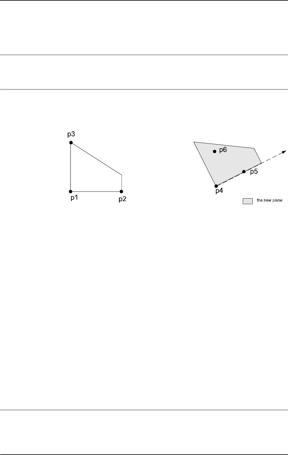
2 Functions
2.33. DefDFrame - Define a displacement frame
RobotWare - OS
8193HAC 16581-1 Revision: J
© Copyright 2004-2010 ABB. All rights reserved.
2.33. DefDFrame - Define a displacement frame
Usage
DefDFrame (Define Displacement Frame) is used to calculate a displacement frame from
three original positions and three displaced positions.
Basic examples
Basic examples of the function
DefDFrame are illustrated below.
Example 1
xx0500002177
CONST robtarget p1 := [...];
CONST robtarget p2 := [...];
CONST robtarget p3 := [...];
VAR robtarget p4;
VAR robtarget p5;
VAR robtarget p6;
VAR pose frame1;
...
!Search for the new positions
SearchL sen1, p4, *, v50, tool1;
...
SearchL sen1, p5, *, v50, tool1;
...
SearchL sen1, p6, *, v50, tool1;
frame1 := DefDframe (p1, p2, p3, p4, p5, p6);
...
!Activation of the displacement defined by frame1
PDispSet frame1;
Three positions p1-p3 related to an object in an original position have been stored. After a
displacement of the object, three new positions are searched for and stored as
p4-p6. The
displacement frame is calculated from these six positions. Then the calculated frame is used
to displace all the stored positions in the program.
Return value
Data type:
pose
The displacement frame.
Continues on next page

2 Functions
2.33. DefDFrame - Define a displacement frame
RobotWare - OS
3HAC 16581-1 Revision: J820
© Copyright 2004-2010 ABB. All rights reserved.
Arguments
DefDFrame (OldP1 OldP2 OldP3 NewP1 NewP2 NewP3)
OldP1
Data type: robtarget
The first original position.
OldP2
Data type: robtarget
The second original position.
OldP3
Data type: robtarget
The third original position.
NewP1
Data type: robtarget
The first displaced position. The difference between OldP1 and NewP1 will define the
translation part of the frame and must be measured and determined with great accuracy.
NewP2
Data type: robtarget
The second displaced position. The line NewP1 ... NewP2 will define the rotation of the
old line
OldP1 ... OldP2.
NewP3
Data type: robtarget
The third displaced position. This position will define the rotation of the plane, e.g. it should
be placed on the new plane of
NewP1, NewP2, and NewP3.
Error handling
If it is not possible to calculate the frame because of bad accuracy in the positions then the
system variable
ERRNO is set to ERR_FRAME. This error can then be handled in the error
handler.
Syntax
DefDFrame’(’
[OldP1 ’:=’] <expression (IN) of robtarget>’ ,’
[OldP2 ’:=’] <expression (IN) of robtarget> ’,’
[OldP3 ’:=’] <expression (IN) of robtarget> ’,’
[NewP1 ’:=’] <expression (IN) of robtarget> ’,’
[NewP2 ’:=’] <expression (IN) of robtarget> ’,’
[NewP3 ’:=’] <expression (IN) of robtarget> ’)’
A function with a return value of the data type pose.
Continued
Continues on next page

2 Functions
2.33. DefDFrame - Define a displacement frame
RobotWare - OS
8213HAC 16581-1 Revision: J
© Copyright 2004-2010 ABB. All rights reserved.
Related information
For information about See
Activation of displacement frame PDispSet - Activates program displacement
using known frame on page 321
Manual definition of displacement frame Operating manual - IRC5 with FlexPendant,
section Calibrating
Continued
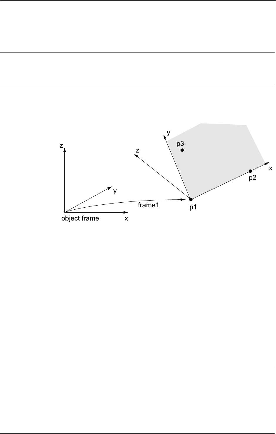
2 Functions
2.34. DefFrame - Define a frame
RobotWare - OS
3HAC 16581-1 Revision: J822
© Copyright 2004-2010 ABB. All rights reserved.
2.34. DefFrame - Define a frame
Usage
DefFrame (Define Frame) is used to calculate a frame, from three positions defining the
frame.
Basic examples
Basic examples of the function
DefFrame are illustrated below.
Example 1
xx0500002181
Three positions, p1- p3 related to the object coordinate system are used to define the new
coordinate system,
frame1. The first position, p1, is defining the origin of the new
coordinate system. The second position,
p2, is defining the direction of the x-axis. The third
position,
p3, is defining the location of the xy-plane. The defined frame1 may be used as a
displacement frame, as shown in the example below:
CONST robtarget p1 := [...];
CONST robtarget p2 := [...];
CONST robtarget p3 := [...];
VAR pose frame1;
...
...
frame1 := DefFrame (p1, p2, p3);
...
...
!Activation of the displacement defined by frame1
PDispSet frame1;
Return value
Data type:
pose
The calculated frame.
The calculation is related to the active object coordinate system.
Continues on next page
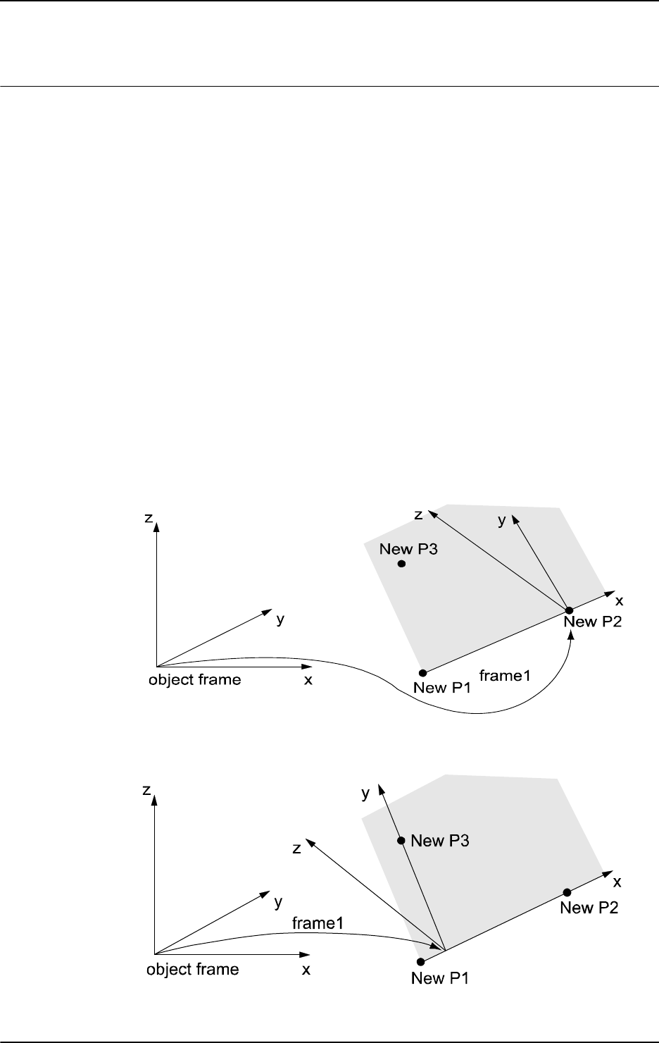
2 Functions
2.34. DefFrame - Define a frame
RobotWare - OS
8233HAC 16581-1 Revision: J
© Copyright 2004-2010 ABB. All rights reserved.
Arguments
DefFrame (NewP1 NewP2 NewP3 [\Origin])
NewP1
Data type: robtarget
The first position, which will define the origin of the new coordinate system.
NewP2
Data type: robtarget
The second position, which will define the direction of the x-axis of the new coordinate
frame.
NewP3
Data type: robtarget
The third position, which will define the xy-plane of the new coordinate system. The position
of point 3 will be on the positive y side, see the figure above.
[\Origin]
Data type: num
Optional argument, which will define how the origin of the new coordinate system will be
placed.
Origin = 1 means that the origin is placed in NewP1, i.e. the same as if this argument
is omitted.
Origin = 2 means that the origin is placed in NewP2. See the figure below.
xx0500002178
Origin = 3 means that the origin is placed on the line going through NewP1 and NewP2 and
so that
NewP3 will be placed on the y axis. See the figure below.
xx0500002180
Other values, or if Origin is omitted, will place the origin in NewP1.
Continued
Continues on next page
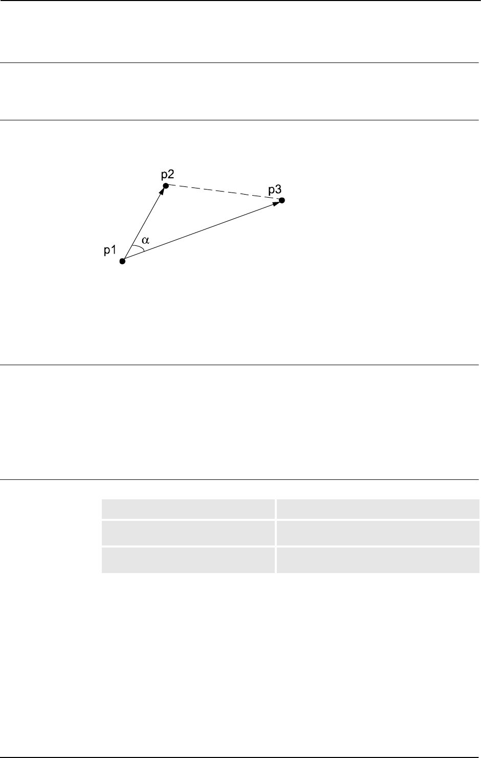
2 Functions
2.34. DefFrame - Define a frame
RobotWare - OS
3HAC 16581-1 Revision: J824
© Copyright 2004-2010 ABB. All rights reserved.
Error handling
If the frame cannot be calculated because of the below limitations then the system variable
ERRNO is set to ERR_FRAME. This error can then be handled in the error handler.
Limitations
The three positions
p1 - p3, defining the frame, must define a well shaped triangle. The
most well shaped triangle is the one with all sides of equal length.
xx0500002182
The triangle is not considered to be well shaped if the angle α is too small. The angle α is too
small if:
|cos α| < 1 - 10
-4
The triangle p1, p2, p3 must not be too small, i.e. the positions cannot be too close. The
distances between the positions
p1 - p2 and p1 - p3 must not be less than 0.1 mm.
Syntax
DefFrame’(’
[NewP1 ’:=’] <expression (IN) of robtarget>’ ,’
[NewP2 ’:=’] <expression (IN) of robtarget> ’,’
[NewP3 ’:=’] <expression (IN) of robtarget>
[’\’Origin’:=’ <expression (IN) of num >]’)’
A function with a return value of the data type pose.
Related information
For information about See
Mathematical instructions and functions Technical reference manual - RAPID overview,
section RAPID summary - Mathematics
Activation of displacement frame PDispSet - Activates program displacement
using known frame on page 321
Continued

2 Functions
2.35. Dim - Obtains the size of an array
RobotWare - OS
8253HAC 16581-1 Revision: J
© Copyright 2004-2010 ABB. All rights reserved.
2.35. Dim - Obtains the size of an array
Usage
Dim (Dimension) is used to obtain the number of elements in an array.
Basic examples
Basic examples of the function
Dim are illustrated below.
See also More examples on page 826.
Example 1
PROC arrmul(VAR num array{*}, num factor)
FOR index FROM 1 TO Dim(array, 1) DO
array{index} := array{index} * factor;
ENDFOR
ENDPROC
All elements of a num array are multiplied by a factor. This procedure can take any one-
dimensional array of data type
num as an input.
Return value
Data type:
num
The number of array elements of the specified dimension.
Arguments
Dim (ArrPar DimNo)
ArrPar
Array Parameter
Data type: Any type
The name of the array.
DimNo
Dimension Number
Data type:
num
The desired array dimension:
1 = first dimension
2 = second dimension
3 = third dimension
Continues on next page

2 Functions
2.35. Dim - Obtains the size of an array
RobotWare - OS
3HAC 16581-1 Revision: J826
© Copyright 2004-2010 ABB. All rights reserved.
More examples
More examples of how to use the function
Dim are illustrated below.
Example 1
PROC add_matrix(VAR num array1{*,*,*}, num array2{*,*,*})
IF Dim(array1,1) <> Dim(array2,1) OR Dim(array1,2) <>
Dim(array2,2) OR Dim(array1,3) <> Dim(array2,3) THEN
TPWrite "The size of the matrices are not the same";
Stop;
ELSE
FOR i1 FROM 1 TO Dim(array1, 1) DO
FOR i2 FROM 1 TO Dim(array1, 2) DO
FOR i3 FROM 1 TO Dim(array1, 3) DO
array1{i1,i2,i3} := array1{i1,i2,i3} +
array2{i1,i2,i3};
ENDFOR
ENDFOR
ENDFOR
ENDIF
RETURN;
ENDPROC
Two matrices are added. If the size of the matrices differs then the program stops and an error
message appears.
This procedure can take any three-dimensional array of data type
num as an input.
Syntax
Dim ’(’
[ArrPar’:=’] <reference (REF) of any type> ’,’
[DimNo’:=’] <expression (IN) of num> ’)’
A REF parameter requires that the corresponding argument be either a constant, a variable,
or an entire persistent. The argument could also be an IN parameter, a VAR parameter, or an
entire PERS parameter.
A function with a return value of the data type
num.
Related information
For information about See
Array parameters Technical reference manual - RAPID overview,
section Basic characteristics - Routines
Array declaration Technical reference manual - RAPID overview,
section Basic characteristics - Data
Continued
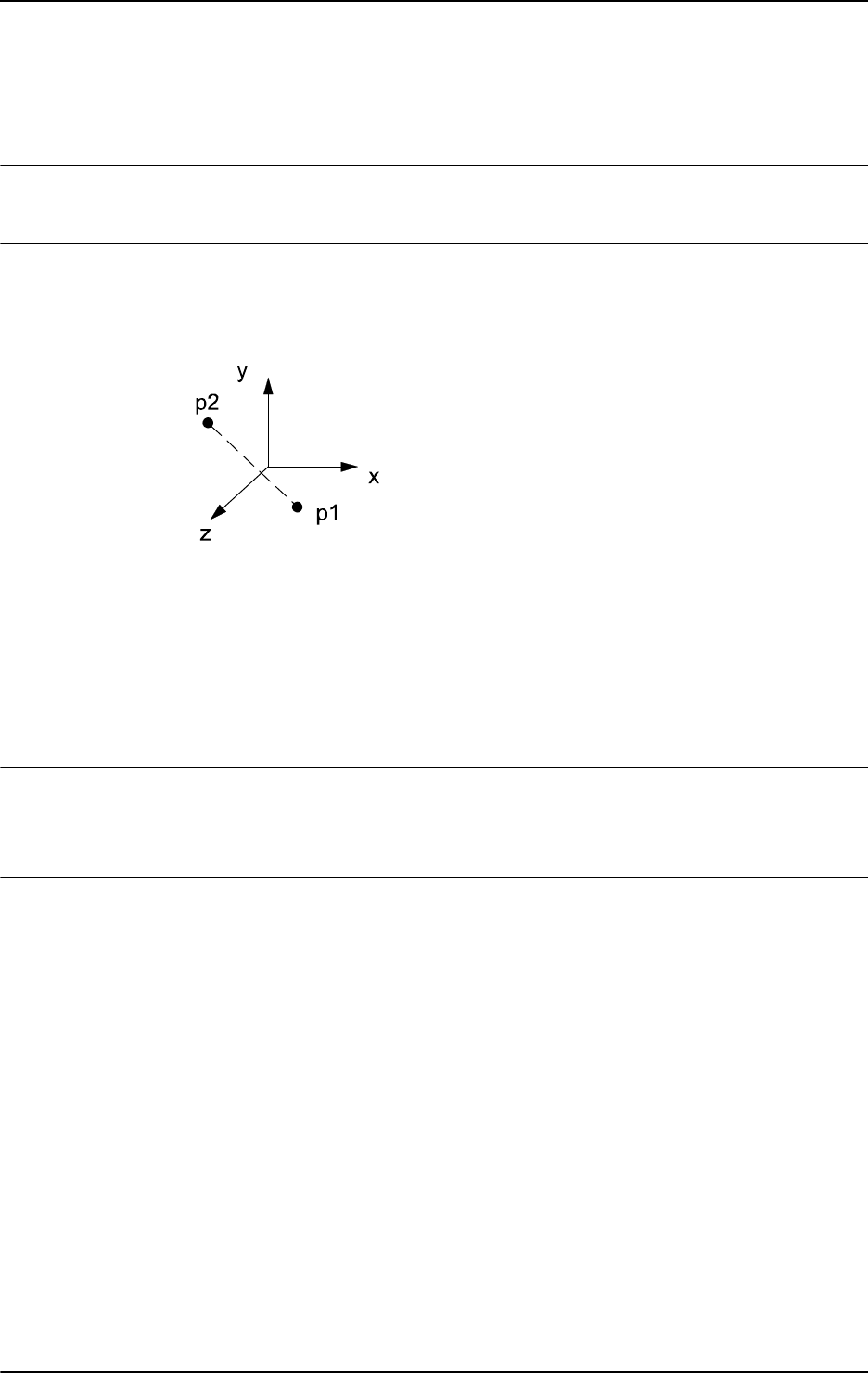
2 Functions
2.36. Distance - Distance between two points
RobotWare - OS
8273HAC 16581-1 Revision: J
© Copyright 2004-2010 ABB. All rights reserved.
2.36. Distance - Distance between two points
Usage
Distance is used to calculate the distance between two points in the space.
Basic examples
Basic examples of the function
Distance are illustrated below.
Example 1
xx0500002321
VAR num dist;
CONST pos p1 := [4,0,4];
CONST pos p2 := [-4,4,4];
...
dist := Distance(p1, p2);
The distance in space between the points p1 and p2 is calculated and stored in the variable
dist.
Return value
Data type:
num
The distance (always positive) in mm between the points.
Arguments
Distance (Point1 Point2)
Point1
Data type: pos
The first point described by the pos data type.
Point2
Data type: pos
The second point described by the pos data type.
Continues on next page
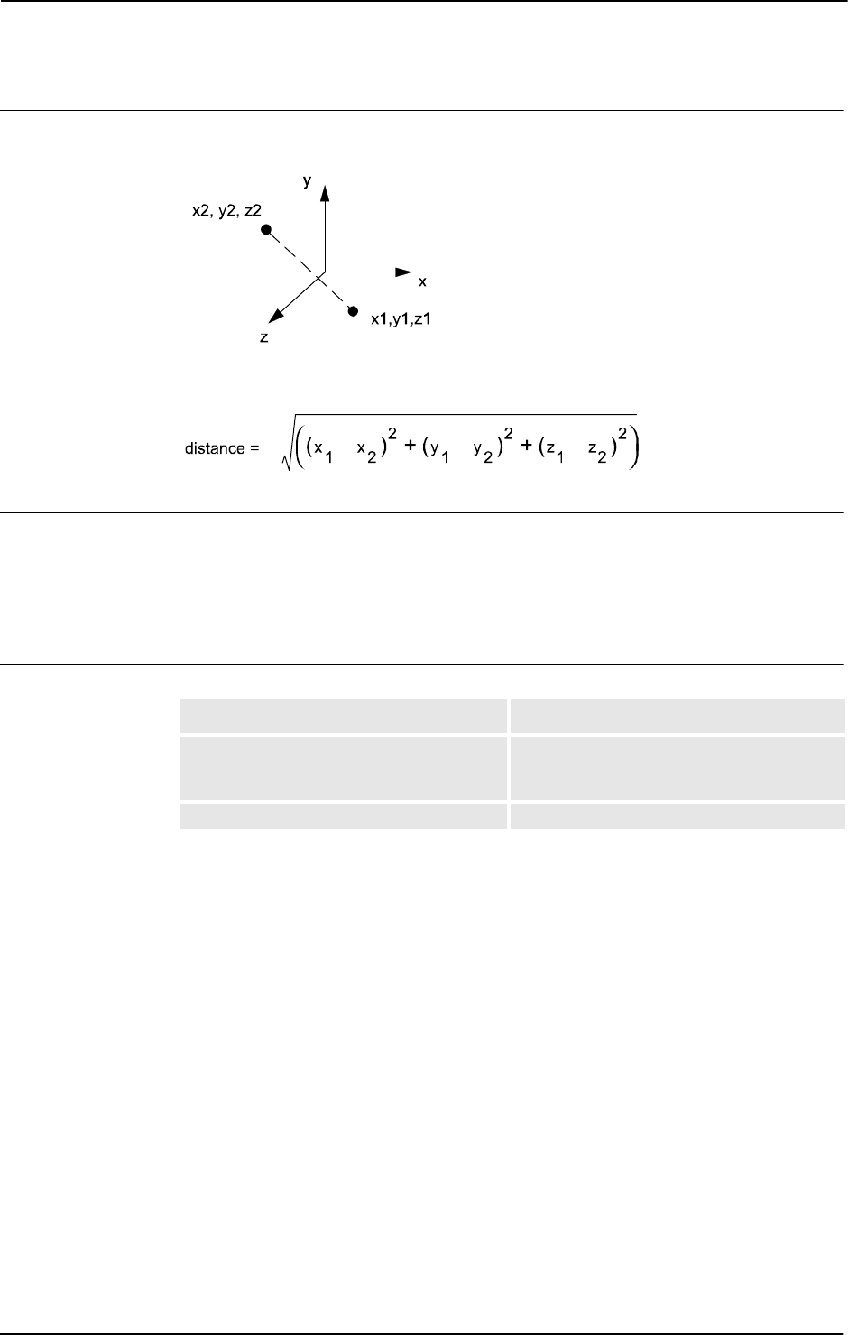
2 Functions
2.36. Distance - Distance between two points
RobotWare - OS
3HAC 16581-1 Revision: J828
© Copyright 2004-2010 ABB. All rights reserved.
Program execution
Calculation of the distance between the two points:
xx0500002322
xx0500002323
Syntax
Distance’(’
[Point1 ’:=’] <expression (IN) of pos> ’,’
[Point2 ’:=’] <expression (IN) of pos> ’)’
A function with a return value of the data type num.
Related information
For information about See
Mathematical instructions and functions Technical reference manual - RAPID
overview, section RAPID Summary -
Mathematics
Definition of pos pos - Positions (only X, Y and Z) on page 1160
Continued

2 Functions
2.37. DnumToNum - Converts dnum to num
RobotWare - OS
8293HAC 16581-1 Revision: J
© Copyright 2004-2010 ABB. All rights reserved.
2.37. DnumToNum - Converts dnum to num
Usage
DnumToNum converts a dnum to a num if possible, otherwise it generates a recoverable error.
Basic examples
A basic example of the function
DnumToNum is illustrated below.
Example 1
VAR num mynum:=0;
VAR dnum mydnum:=8388607;
VAR dnum testFloat:=8388609;
VAR dnum anotherdnum:=4294967295;
! Works OK
mynum:=DnumToNum(mydnum);
! Accept floating point value
mynum:=DnumToNum(testFloat);
! Cause error recovery error
mynum:=DnumToNum(anotherdnum \Integer);
The dnum value 8388607 is returned by the function as the num value 8388607.
The dnum value 8388609 is returned by the function as the num value
8.38861E+06.
The dnum value 4294967295 generates the recoverable error
ERR_ARGVALERR.
Return value
Data type:
num
The input dnum value can be in the range -8388607 to 8388608 and return the same value as
a
num. If the \Integer switch is not used, the input dnum value can be in the range -
3.40282347E+38 to 3.40282347E+38 and the return value might become a floating point
value.
Arguments
DnumToNum (Value [\Integer])
Value
Data type: dnum
The numeric value to be converted.
[\Integer]
Data type: switch
Only integer values
If switch
\Integer is not used, an down cast is made even if the value becomes a floating
point value. If it is not used, a check is made whether the value is an integer between -8388607
to 8388608. If it is not, a recoverable error is generated.
Continues on next page

2 Functions
2.37. DnumToNum - Converts dnum to num
RobotWare - OS
3HAC 16581-1 Revision: J830
© Copyright 2004-2010 ABB. All rights reserved.
Error handling
The following recoverable errors can be generated. The errors can be handled in an error
handler. The system variable
ERRNO will be set to:
Syntax
DnumToNum
[ Value ’:=’ ] < expression (IN) of dnum >
[\ Integer]’ ;’
A function with a return value of the data type num.
Related information
Error code Description
ERR_ARGVALERR Value is above 8388608 or below -8388607 or not an integer (if
optional argument Integer is used)
ERR_NUM_LIMIT Value is above 3.40282347E+38 or below -3.40282347E+38
ERR_INT_NOTVAL Value is not an integer
For information about See
Dnum data type dnum - Double numeric values on page 1104.
Num data type num - Numeric values on page 1146.
Continued
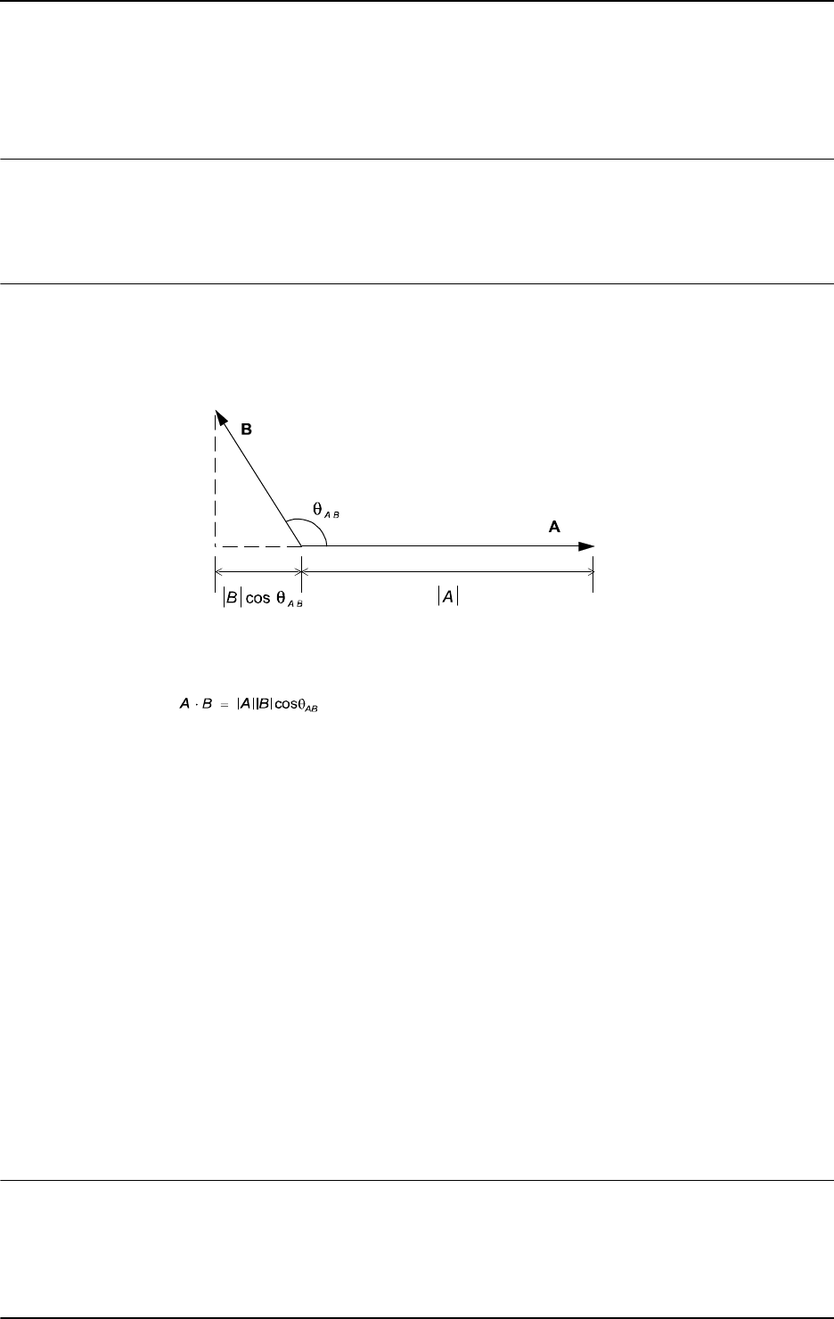
2 Functions
2.38. DotProd - Dot product of two pos vectors
RobotWare - OS
8313HAC 16581-1 Revision: J
© Copyright 2004-2010 ABB. All rights reserved.
2.38. DotProd - Dot product of two pos vectors
Usage
DotProd (Dot Product) is used to calculate the dot (or scalar) product of two pos vectors. The
typical use is to calculate the projection of one vector upon the other or to calculate the angle
between the two vectors.
Basic examples
Basic examples of the function
DotProd are illustrated below.
Example 1
xx0500002449
The dot or scalar product of two vectors A and B is a scalar, which equals the products of the
magnitudes of A and B and the cosine of the angle between them.
.
The dot product:
• is less than or equal to the product of their magnitudes.
• can be either a positive or a negative quantity, depending on whether the angle
between them is smaller or larger then 90 degrees.
• is equal to the product of the magnitude of one vector and the projection of the other
vector upon the first one.
• is zero when the vectors are perpendicular to each other.
The vectors are described by the data type
pos and the dot product by the data type num:
VAR num dotprod;
VAR pos vector1;
VAR pos vector2;
...
...
vector1 := [1,1,1];
vector2 := [1,2,3];
dotprod := DotProd(vector1, vector2);
Return value
Data type:
num
The value of the dot product of the two vectors.
Continues on next page

2 Functions
2.38. DotProd - Dot product of two pos vectors
RobotWare - OS
3HAC 16581-1 Revision: J832
© Copyright 2004-2010 ABB. All rights reserved.
Arguments
DotProd (Vector1 Vector2)
Vector1
Data type: pos
The first vector described by the pos data type.
Vector2
Data type: pos
The second vector described by the pos data type.
Syntax
DotProd’(’
[Vector1 ’:=’] <expression (IN) of pos>’,’
[Vector2 ’:=’] <expression (IN) of pos>
’)’
A function with a return value of the data type num.
Related information
For information about See
Mathematical instructions and functions Technical reference manual - RAPID
overview, section RAPID summary -
Mathematics
Continued

2 Functions
2.39. DOutput - Reads the value of a digital output signal
RobotWare - OS
8333HAC 16581-1 Revision: J
© Copyright 2004-2010 ABB. All rights reserved.
2.39. DOutput - Reads the value of a digital output signal
Usage
DOutput is used to read the current value of a digital output signal.
Basic examples
Basic examples of the function
DOutput are illustrated below.
See also More examples on page 833.
Example 1
IF DOutput(do2) = 1 THEN...
If the current value of the signal do2 is equal to 1, then...
Return value
Data type:
dionum
The current value of the signal (0 or 1).
Arguments
DOutput (Signal)
Signal
Data type: signaldo
The name of the signal to be read.
Program execution
The value read depends on the configuration of the signal. If the signal is inverted in the
system parameters then the value returned by this function is the opposite of the true value of
the physical channel.
Error handling
The following recoverable error can be generated. The error can be handled in an error
handler. The system variable
ERRNO will be set to:
ERR_NORUNUNIT if there is no contact with the unit.
More examples
More examples of the function
DOutput are illustrated below.
Example 1
IF DOutput(auto_on) <> active THEN . . .
If the current value of the system signal auto_on is not active then ..., i.e. if the robot
is in the manual operating mode, then
...
NOTE!
The signal must first be defined as a system output in the system parameters.
Continues on next page

2 Functions
2.39. DOutput - Reads the value of a digital output signal
RobotWare - OS
3HAC 16581-1 Revision: J834
© Copyright 2004-2010 ABB. All rights reserved.
Syntax
DOutput ’(’
[ Signal ’:=’ ] < variable (VAR) of signaldo > ’)’
A function with a return value of the data type dionum.
Related information
For information about See
Set a digital output signal SetDO - Changes the value of a digital output signal
on page 440
Input/Output instructions Technical reference manual - RAPID overview,
section RAPID Summary - Input and Output Signals
Input/Output functionality in general Technical reference manual - RAPID overview,
section Motion and I/O Principles - I/O Principles
Configuration of I/O Technical reference manual - System parameters
Continued

2 Functions
2.40. EulerZYX - Gets euler angles from orient
RobotWare - OS
8353HAC 16581-1 Revision: J
© Copyright 2004-2010 ABB. All rights reserved.
2.40. EulerZYX - Gets euler angles from orient
Usage
EulerZYX (Euler ZYX rotations) is used to get an Euler angle component from an orient
type variable.
Basic examples
Basic examples of the function
EulerZYX are illustrated below.
Example 1
VAR num anglex;
VAR num angley;
VAR num anglez;
VAR pose object;
...
...
anglex := EulerZYX(\X, object.rot);
angley := EulerZYX(\Y, object.rot);
anglez := EulerZYX(\Z, object.rot);
Return value
Data type:
num
The corresponding Euler angle, expressed in degrees, range from [-180, 180].
Arguments
EulerZYX ([\X] | [\Y] | [\Z] Rotation)
[\X]
Data type: switch
Gets the rotation around the X axis.
[\Y]
Data type: switch
Gets the rotation around the Y axis.
[\Z]
Data type: switch
Gets the rotation around the Z axis.
Note!
The arguments
\X, \Y, and \Z are mutually exclusive. If none of these are specified then a
run-time error is generated.
Rotation
Data type: orient
The rotation in its quaternion representation.
Continues on next page

2 Functions
2.40. EulerZYX - Gets euler angles from orient
RobotWare - OS
3HAC 16581-1 Revision: J836
© Copyright 2004-2010 ABB. All rights reserved.
Syntax
EulerZYX’(’
['\'X ’,’] | ['\'Y’ ,’] | ['\'Z’,’]
[Rotation’:=’] <expression (IN) of orient>
’)’
A function with a return value of the data type num.
Related information
For information about See
Mathematical instructions and functions Technical reference manual - RAPID
overview, section RAPID summary -
Mathematics
Continued

2 Functions
2.41. EventType - Get current event type inside any event routine
RobotWare - OS
8373HAC 16581-1 Revision: J
© Copyright 2004-2010 ABB. All rights reserved.
2.41. EventType - Get current event type inside any event routine
Usage
EventType can be used in any event routine and then returns the current executed event type.
If
EventType is called from any program task routine then EventType always returns 0
meaning EVENT_NONE.
Basic examples
Basic examples of the function
EventType are illustrated below.
Example 1
TEST EventType()
CASE EVENT_NONE:
! Not executing any event
CASE EVENT_POWERON:
! Executing POWER ON event
CASE EVENT_START:
! Executing START event
CASE EVENT_STOP:
! Executing STOP event
CASE EVENT_QSTOP:
! Executing QSTOP event
CASE EVENT_RESTART:
! Executing RESTART event
CASE EVENT_RESET:
! Executing RESET event
CASE EVENT_STEP:
! Executing STEP event
ENDTEST
Use of function EventType inside any event routine to find out which system event, if any,
is executing now.
Return value
Data type:
event_type
The current executed event type 1 ... 7, or 0 if no event routine is executed.
Predefined data
The following predefined symbolic constants of type
event_type can be used to check the
return value:
CONST event_type EVENT_NONE := 0;
CONST event_type EVENT_POWERON := 1;
CONST event_type EVENT_START := 2;
CONST event_type EVENT_STOP := 3;
CONST event_type EVENT_QSTOP:= 4;
CONST event_type EVENT_RESTART := 5;
CONST event_type EVENT_RESET := 6;
CONST event_type EVENT_STEP := 7;
Continues on next page

2 Functions
2.41. EventType - Get current event type inside any event routine
RobotWare - OS
3HAC 16581-1 Revision: J838
© Copyright 2004-2010 ABB. All rights reserved.
Syntax
EventType’(’ ’)’
A function with a return value of the data type event_type.
Related information
For information about See
Event routines in general Technical reference manual - System
parameters, section Controller - Event Routine
Data type event_type, predefined constants event_type - Event routine type on page 1116
Continued

2 Functions
2.42. ExecHandler - Get type of execution handler
RobotWare - OS
8393HAC 16581-1 Revision: J
© Copyright 2004-2010 ABB. All rights reserved.
2.42. ExecHandler - Get type of execution handler
Usage
ExecHandler can be used to find out if the actual RAPID code is executed in any RAPID
program routine handler.
Basic examples
Basic example of the function
ExecHandler is illustrated below.
Example 1
TEST ExecHandler()
CASE HANDLER_NONE:
! Not executing in any routine handler
CASE HANDLER_BWD:
! Executing in routine BACKWARD handler
CASE HANDLER_ERR:
! Executing in routine ERROR handler
CASE HANDLER_UNDO:
! Executing in routine UNDO handler
ENDTEST
Use of function ExecHandler to find out if the code is executing in some type of routine
handler or not.
HANDLER_ERR will be returned even if the call is executed in a submethod to the error
handler.
Return value
Data type:
handler_type
The current executed handler type 1 ... 3, or 0 if not executing in any routine handler.
Predefined data
The following predefined symbolic constants of type
handler_type can be used to check
the return value:
CONST handler_type HANDLER_NONE := 0;
CONST handler_type HANDLER_BWD := 1;
CONST handler_type HANDLER_ERR := 2;
CONST handler_type HANDLER_UNDO := 3;
Syntax
ExecHandler’(’ ’)’
A function with a return value of the data type handler_type.
Related information
For information about See
Type of execution handler handler_type - Type of execution handler on
page 1120

2 Functions
2.43. ExecLevel - Get execution level
RobotWare - OS
3HAC 16581-1 Revision: J840
© Copyright 2004-2010 ABB. All rights reserved.
2.43. ExecLevel - Get execution level
Usage
ExecLevel can be used to find out current execution level for the RAPID code that currently
is executed.
Basic examples
Basic example of the function
ExecLevel is illustrated below.
Example 1
TEST ExecLevel()
CASE LEVEL_NORMAL:
! Execute on base level
CASE LEVEL_TRAP:
! Execute in TRAP routine
CASE LEVEL_SERVICE:
! Execute in service, event or system input interrupt routine
ENDTEST
Use of function ExecLevel to find out the current execution level.
Return value
Data type:
exec_level
The current execution level 0... 2.
Predefined data
The following predefined symbolic constants of type
event_level can be used to check the
return value:
CONST exec_level LEVEL_NORMAL := 0;
CONST exec_level LEVEL_TRAP := 1;
CONST exec_level LEVEL_SERVICE := 2;
Syntax
ExecLevel’(’ ’)’
A function with a return value of the data type exec_level.
Related information
For information about See
Data type for execution level exec_level - Execution level on page 1117

2 Functions
2.44. Exp - Calculates the exponential value
RobotWare - OS
8413HAC 16581-1 Revision: J
© Copyright 2004-2010 ABB. All rights reserved.
2.44. Exp - Calculates the exponential value
Usage
Exp (Exponential) is used to calculate the exponential value, e
x
.
Basic examples
Basic examples of the function
Exp are illustrated below.
Example 1
VAR num x;
VAR num value;
...
value:= Exp( x);
value will get the exponential value of x.
Return value
Data type:
num
The exponential value e
x
.
Arguments
Exp (Exponent)
Exponent
Data type: num
The exponent argument value.
Syntax
Exp’(’
[Exponent ’:=’] <expression (IN) of num>’)’
A function with a return value of the data type num.
Related information
For information about See
Mathematical instructions and functions Technical reference manual - RAPID overview,
section RAPID Summary - Mathematics

2 Functions
2.45. FileSize - Retrieve the size of a file
RobotWare - OS
3HAC 16581-1 Revision: J842
© Copyright 2004-2010 ABB. All rights reserved.
2.45. FileSize - Retrieve the size of a file
Usage
FileSize is used to retrieve the size of the specified file.
Basic examples
Basic examples of the function
FileSize are illustrated below.
See also More examples on page 842.
Example 1
PROC listfile(string filename)
VAR num size;
size := FileSize(filename);
TPWrite filename+" size: "+NumToStr(size,0)+" Bytes";
ENDPROC
This procedure prints out the name of specified file together with a size specification.
Return value
Data type:
num
The size in bytes.
Arguments
FileSize (Path)
Path
Data type: string
The file name specified with full or relative path.
Program execution
This function returns a numeric that specifies the size in bytes of the specified file.
It is also possible to get the same information about a directory.
More examples
Basic examples of the function are illustrated below.
Example 1
This example lists all files bigger than 1 KByte under the "HOME:" directory structure,
including all subdirectories.
PROC searchdir(string dirname, string actionproc)
VAR dir directory;
VAR string filename;
IF IsFile(dirname \Directory) THEN
OpenDir directory, dirname;
WHILE ReadDir(directory, filename) DO
! .. and . is the parent and resp. this directory
IF filename <> ".." AND filename <> "." THEN
searchdir dirname+"/"+filename, actionproc;
Continues on next page

2 Functions
2.45. FileSize - Retrieve the size of a file
RobotWare - OS
8433HAC 16581-1 Revision: J
© Copyright 2004-2010 ABB. All rights reserved.
ENDIF
ENDWHILE
CloseDir directory;
ELSE
%actionproc% dirname;
ENDIF
ERROR
RAISE;
ENDPROC
PROC listfile(string filename)
IF FileSize(filename) > 1024 THEN
TPWrite filename;
ENDIF
ENDPROC
PROC main()
! Execute the listfile routine for all files found under the
! tree of HOME:
searchdir "HOME:","listfile";
ENDPROC
This program traverses the directory structure under "HOME:" and for each file found it calls
the
listfile procedure. The searchdir is a generic part that knows nothing about the start
of the search or which routine should be called for each file. It uses
IsFile to check whether
it has found a subdirectory or a file and it uses the late binding mechanism to call the
procedure specified in
actionproc for all files found. The actionproc routine listfile
checks whether the file is bigger than
1KBytes.
Error handling
If the file does not exist, the system variable
ERRNO is set to ERR_FILEACC. This error can
then be handled in the error handler.
Syntax
FileSize ’(’
[ Path ’:=’ ] < expression (IN) of string> ’)’
A function with a return value of the data type num.
Continued
Continues on next page

2 Functions
2.45. FileSize - Retrieve the size of a file
RobotWare - OS
3HAC 16581-1 Revision: J844
© Copyright 2004-2010 ABB. All rights reserved.
Related information
For information about See
Make a directory MakeDir - Create a new directory on page 218
Remove a directory RemoveDir - Delete a directory on page 355
Rename a file RenameFile - Rename a file on page 357
Remove a file RemoveFile - Delete a file on page 356
Copy a file CopyFile - Copy a file on page 65
Check file type IsFile - Check the type of a file on page 878
Check file system size FSSize - Retrieve the size of a file system on page 848
Continued

2 Functions
2.46. FileTime - Retrieve time information about a file
RobotWare-OS
8453HAC 16581-1 Revision: J
© Copyright 2004-2010 ABB. All rights reserved.
2.46. FileTime - Retrieve time information about a file
Usage
FileTime is used to retrieve the last time for modification, access or file status change of a
file. The time is measured in seconds since 00:00:00 GMT, Jan. 1 1970. The time is returned
as a
num and optionally also in a stringdig.
Basic example
Basic examples of the function
FileTime are illustrated below.
See also More examples on page 846.
Example 1
IF FileTime ("HOME:/mymod.mod" \ModifyTime)
> ModTime ("mymod") THEN
UnLoad "HOME:mymod.mod";
Load \Dynamic, "HOME:mymod.mod";
ENDIF
This program reloads a module if the source file is newer. It uses the ModTime to retrieve the
latest modification time for the specified module, and to compare it to the
FileTime\ModifyTime at the source. Then, if the source is newer, the program unloads and
loads the module again.
Limitation in this example: The data type
num cannot handle positive integers above 8388608
seconds with exact representation. To get better dissolution, see example in function
StrDigCmp.
Return value
Data type:
num
The time measured in seconds since 00:00:00 GMT, Jan. 1 1970.
Arguments
FileTime ( Path [\ModifyTime] | [\AccessTime] | [\StatCTime]
[\StrDig])
Path
Data type: string
The file specified with a full or relative path.
[\ModifyTime]
Data type: switch
Last modification time.
[\AccessTime]
Data type: switch
Time of last access (read, execute of modify).
[\StatCTime]
Data type: switch
Last file status (access qualification) change time.
Continues on next page

2 Functions
2.46. FileTime - Retrieve time information about a file
RobotWare-OS
3HAC 16581-1 Revision: J846
© Copyright 2004-2010 ABB. All rights reserved.
[\StrDig]
String Digit
Data type:
stringdig
To get the file time in a stringdig representation.
Further use in
StrDigCmp can handle positive integers above 8388608 with exact
representation.
Program execution
This function returns a numeric that specifies the time since the last:
• Modification
• Access
• File status change
of the specified file.
It is also possible to get the same information about a directory.
More examples
More examples of the function
FileTime are illustrated below.
This is a complete example that implements an alert service for maximum 10 files.
LOCAL RECORD falert
string filename;
num ftime;
ENDRECORD
LOCAL VAR falert myfiles[10];
LOCAL VAR num currentpos:=0;
LOCAL VAR intnum timeint;
PROC alertInit(num freq)
currentpos:=0;
CONNECT timeint WITH mytrap;
ITimer freq,timeint;
ENDPROC
LOCAL TRAP mytrap
VAR num pos:=1;
WHILE pos <= currentpos DO
IF FileTime(myfiles{pos}.filename \ModifyTime) >
myfiles{pos}.ftime THEN
TPWrite "The file "+myfiles{pos}.filename+" is changed";
ENDIF
pos := pos+1;
ENDWHILE
ENDTRAP
Continued
Continues on next page

2 Functions
2.46. FileTime - Retrieve time information about a file
RobotWare-OS
8473HAC 16581-1 Revision: J
© Copyright 2004-2010 ABB. All rights reserved.
PROC alertNew(string filename)
currentpos := currentpos+1;
IF currentpos <= 10 THEN
myfiles{currentpos}.filename := filename;
myfiles{currentpos}.ftime := FileTime (filename \ModifyTime);
ENDIF
ENDPROC
PROC alertFree()
IDelete timeint;
ENDPROC
Error handling
If the file does not exist, the system variable ERRNO is set to ERR_FILEACC. This error can
then be handled in the error handler.
Syntax
FileTime ’(’
[ Path ’:=’ ] < expression (IN) of string>
[ '\'ModifyTime] |
[ '\'AccessTime] |
[ '\'StatCTime]
[ '\' StrDig’ :=’ < variable (VAR) of stringdig> ] ’)’
A function with a return value of the data type num.
Related information
For information about See
Last modify time of a loaded module ModTime - Get file modify time for the loaded
module on page 896
String with only digits ModTime - Get file modify time for the loaded
module on page 896
stringdig - String with only digits on page 1197
Compare two strings with only digits ModTime - Get file modify time for the loaded
module on page 896
StrDigCmp - Compare two strings with only
digits on page 991
Continued

2 Functions
2.47. FSSize - Retrieve the size of a file system
RobotWare - OS
3HAC 16581-1 Revision: J848
© Copyright 2004-2010 ABB. All rights reserved.
2.47. FSSize - Retrieve the size of a file system
Usage
FSSize (File System Size) is used to retrieve the size of the file system in which a specified
file resides. The size in bytes, kilo bytes or mega bytes are returned as a
num.
Basic example
Basic examples of the function
FSSize are illustrated below.
See also More examples on page 849.
Example 1
PROC main()
VAR num totalfsyssize;
VAR num freefsyssize;
freefsyssize := FSSize("HOME:/spy.log" \Free);
totalfsyssize := FSSize("HOME:/spy.log" \Total);
TPWrite NumToStr(((totalfsyssize - freefsyssize)/
totalfsyssize)*100,0)
+" percent used";
ENDPROC
This procedure prints out the amount of disk space used on the HOME: file system (flash disk
/hd0a/) as a percentage.
Return value
Data type:
num
The size in bytes.
Arguments
FSSize (Name [\Total] | [\Free] [\Kbyte] [\Mbyte])
Name
Data type: string
The name of a file in the file system, specified with full or relative path.
[ \Total ]
Data type: switch
Retrieves the total amount of space in the file system.
[ \Free ]
Data type: switch
Retrieves the amount of free space in the file system.
[ \Kbyte ]
Data type: switch
Convert the number of bytes read to kilobytes, e.g divide the size with 1024.
Continues on next page

2 Functions
2.47. FSSize - Retrieve the size of a file system
RobotWare - OS
8493HAC 16581-1 Revision: J
© Copyright 2004-2010 ABB. All rights reserved.
[ \Mbyte ]
Data type: switch
Convert the number of bytes read to megabytes, e.g divide the size with 1048576
(1024*1024).
Program execution
This function returns a numeric that specifies the size of the file system in which the specified
file resides.
More examples
More examples of the function
FSSize are illustrated below.
Example 1
LOCAL VAR intnum timeint;
LOCAL TRAP mytrap
IF FSSize("HOME:/spy.log" \Free)/FSSize("HOME:/spy.log" \Total)
<= 0.1 THEN
TPWrite "The disk is almost full";
alertFree;
ENDIF
ENDTRAP
PROC alertInit(num freq)
CONNECT timeint WITH mytrap;
ITimer freq,timeint;
ENDPROC
PROC alertFree()
IDelete timeint;
ENDPROC
This is a complete example for implementing an alert service that prints a warning on the
FlexPendant when the remaining free space in the "
HOME:" file system is less than 10%.
Error handling
The following recoverable errors can be generated. The errors can be handled in an
ERROR
handler. The system variable
ERRNO will be set to:
Syntax
FSSize’(’
[ Name ’:=’ ] < expression (IN) of string>
[ ´\´Total ] | [ ´\´Free ]
[ ´\´Kbyte ]
[ ´\´Mbyte ]’)’
A function with a return value of the data type num.
ERR_FILEACC The file system does not exist
ERR_FILESIZE The size exceeds the max integer value for a num, 8388608
Continued
Continues on next page

2 Functions
2.47. FSSize - Retrieve the size of a file system
RobotWare - OS
3HAC 16581-1 Revision: J850
© Copyright 2004-2010 ABB. All rights reserved.
Related information
For information about See
Make a directory MakeDir - Create a new directory on page 218
Remove a directory RemoveDir - Delete a directory on page 355
Rename a file RenameFile - Rename a file on page 357
Remove a file RemoveFile - Delete a file on page 356
Copy a file CopyFile - Copy a file on page 65
Check file type IsFile - Check the type of a file on page 878
Check file size FileSize - Retrieve the size of a file on page 842
Continued

2 Functions
2.48. GetMecUnitName - Get the name of the mechanical unit
RobotWare - OS
8513HAC 16581-1 Revision: J
© Copyright 2004-2010 ABB. All rights reserved.
2.48. GetMecUnitName - Get the name of the mechanical unit
Usage
GetMecUnitName is used to get the name of a mechanical unit with one of the installed
mechanical units as the argument. This function returns the mechanical units name as a
string.
Basic examples
Basic examples of the function
GetMecUnitName are illustrated below.
Example 1
VAR string mecname;
mecname:= GetMecUnitName(T_ROB1);
mecname
will get the value "T_ROB1"as a string. All mechanical units (data type
mecunit) such as T_ROB1 are predefined in the system.
Return value
Data type:
string
The return value will be the mechanical unit name as a string.
Arguments
GetMecUnitName ( MechUnit )
MechUnit
Mechanical Unit
Data type:
mecunit
MechUnit
takes one of the predefined mechanical units found in the configuration.
Syntax
GetMecUnitName’(’
[ MechUnit ’:=’ ] < variable (VAR) of mecunit > ’)’
A function with a return value of the data type string.
Related information
For information about See
Mechanical unit mecunit - Mechanical unit on page 1139

2 Functions
2.49. GetNextMechUnit - Get name and data for mechanical units
RobotWare - OS
3HAC 16581-1 Revision: J852
© Copyright 2004-2010 ABB. All rights reserved.
2.49. GetNextMechUnit - Get name and data for mechanical units
Usage
GetNextMechUnit (Get Next Mechanical Unit) is used for retrieving the name of
mechanical units in the robot system. Besides the mechanical unit name, several optional
properties of the mechanical unit can be retrieved.
Basic examples
Basic examples of the function
GetNextMechUnit are illustrated below.
See also More examples on page 853.
Example 1
VAR num listno := 0;
VAR string name := "";
TPWrite "List of mechanical units:";
WHILE GetNextMechUnit(listno, name) DO
TPWrite name;
! listno := listno + 1 is done by GetNextMechUnit
ENDWHILE
The name of all mechanical units available in the system, will be displayed on the
FlexPendant.
Return Value
Data type:
bool
TRUE
if a mechanical unit was found, otherwise FALSE.
Arguments
GetNextMechUnit ( ListNumber UnitName [\MecRef] [\TCPRob]
[\NoOfAxes] [\MecTaskNo] [\MotPlanNo] [\Active]
[\DriveModule] [\OKToDeact])
ListNumber
Data type: num
This specifies which items in the system internal list of mechanical units are to be retrieved.
At return, this variable is always incremented by one by the system to make it easy to access
the next unit in the list. The first mechanical unit in the list has index 0.
UnitName
Data type: string
The name of the mechanical unit.
[\MecRef]
Data type: mecunit
The system reference to the mechanical unit.
Continues on next page

2 Functions
2.49. GetNextMechUnit - Get name and data for mechanical units
RobotWare - OS
8533HAC 16581-1 Revision: J
© Copyright 2004-2010 ABB. All rights reserved.
[\TCPRob]
Data type: bool
TRUE if the mechanical unit is a TCP robot, otherwise FALSE.
[\NoOfAxes]
Data type: num
Number of axes for the mechanical unit. Integer value.
[\MecTaskNo]
Data type: num
The program task number that controls the mechanical unit. Integer value in range 1-20. If
not controlling by any program task, -1 is returned.
This actual connection is defined in the system parameters domain controller (can in some
application be redefined at runtime).
[\MotPlanNo]
Data type: num
The motion planner number that controls the mechanical unit. Integer value in range 1-6. If
not controlling by any motion planner, -1 is returned.
This connection is defined in the system parameters domain controller.
[\Active]
Data type: bool
TRUE if the mechanical unit is active, otherwise FALSE.
[\DriveModule]
Data type: num
The Drive Module number 1 - 4 used by this mechanical unit.
[\OKToDeact]
Data type: bool
Return TRUE, if allowed to deactivate the mechanical unit from RAPID program.
More examples
More examples of the instruction
GetNextMechUnit are illustrated below.
Example 1
VAR num listno := 4;
VAR string name := "";
VAR bool found := FALSE;
found := GetNextMechUnit (listno, name);
If found is set to TRUE, the name of mechanical unit number 4 will be in the variable name,
else
name contains only an empty string.
Continued
Continues on next page

2 Functions
2.49. GetNextMechUnit - Get name and data for mechanical units
RobotWare - OS
3HAC 16581-1 Revision: J854
© Copyright 2004-2010 ABB. All rights reserved.
Syntax
GetNextMechUnit ’(’
[ ListNumber ’:=’ ] < variable (VAR) of num>’ ,’
[ UnitName’ :=’ ] < variable (VAR) of string> ’,’
[ ’\’ MecRef’ :=’ < variable (VAR) of mecunit> ]
[ ’\’ TCPRob’ :=’ < variable (VAR) of bool> ]
[ ’\’ NoOfAxes’ :=’ < variable (VAR) of num> ]
[ ’\’ MecTaskNo’ :=’ < variable (VAR) of num> ]
[ ’\’ MotPlanNo’ :=’ < variable (VAR) of num> ]
[ ’\’ Active’ :=’ < variable (VAR) of bool>]
[ ’\’ DriveModule’ :=’ < variable (VAR) of num>]
[ ’\’ OKToDeact’ :=’ < variable (VAR) of bool>] ’;’
A function with a return value of the data type bool.
Related information
For information about See
Mechanical unit mecunit - Mechanical unit on page 1139
Activating/Deactivating mechanical units ActUnit - Activates a mechanical unit on page
17
DeactUnit - Deactivates a mechanical unit on
page 79
Characteristics of non-value data types Technical reference manual - RAPID
overview, section Basic Characteristics - Data
types
Continued

2 Functions
2.50. GetNextSym - Get next matching symbol
RobotWare - OS
8553HAC 16581-1 Revision: J
© Copyright 2004-2010 ABB. All rights reserved.
2.50. GetNextSym - Get next matching symbol
Usage
GetNextSym (Get Next Symbol) is used together with SetDataSearch to retrieve data
objects from the system.
Basic examples
Basic examples of the function
GetNextSym are illustrated below.
Example 1
VAR datapos block;
VAR string name;
VAR bool truevar:=TRUE;
...
SetDataSearch "bool" \Object:="my.*" \InMod:="mymod"\LocalSym;
WHILE GetNextSym(name,block) DO
SetDataVal name\Block:=block,truevar;
ENDWHILE
This session will set all local bool data objects that begin with my in the module mymod to
TRUE.
Return value
Data type:
bool
TRUE
if a new object has been retrieved, the object name and its enclosed block is then
returned in its arguments.
FALSE if no more objects match.
Arguments
GetNextSym (Object Block [\Recursive])
Object
Data type: string
Variable (VAR or PERS) to store the name of the data object that will be retrieved.
Block
Data type: datapos
The enclosed block to the object.
[ \Recursive ]
Data type: switch
This will force the search to enter the block below, e.g. if the search session has begun at the
task level, it will also search modules and routines below the task.
Continues on next page

2 Functions
2.50. GetNextSym - Get next matching symbol
RobotWare - OS
3HAC 16581-1 Revision: J856
© Copyright 2004-2010 ABB. All rights reserved.
Syntax
GetNextSym ‘(‘
[ Object ’:=’ ] < variable or persistent (INOUT) of string > ’,’
[ Block ’:=’] <variable (VAR) of datapos>
[’\’Recursive ] ’)’
A function with a return value of the data type bool.
Related information
For information about See
Define a symbol set in a search
session
SetDataSearch - Define the symbol set in a search
sequence on page 433
Get the value of a data object GetDataVal - Get the value of a data object on page
110
Set the value of a data object SetDataVal - Set the value of a data object on page
437
Set the value of many data objects SetAllDataVal - Set a value to all data objects in a
defined set on page 429
The related data type datapos datapos - Enclosing block for a data object on page
1101
Continued

2 Functions
2.51. GetSysInfo - Get information about the system
RobotWare - OS
8573HAC 16581-1 Revision: J
© Copyright 2004-2010 ABB. All rights reserved.
2.51. GetSysInfo - Get information about the system
Usage
GetSysInfo is used to read information about the system. Available information includes
Serial Number, SoftWare Version, Robot Type, Controller ID or Lan ip address.
Basic examples
Basic examples of the function
GetSysInfo are illustrated below.
Example 1
VAR string serial;
VAR string version;
VAR string rtype;
VAR string cid;
VAR string lanip;
VAR string clang;
serial := GetSysInfo(\SerialNo);
version := GetSysInfo(\SWVersion);
rtype := GetSysInfo(\RobotType);
cid := GetSysInfo(\CtrlId);
lanip := GetSysInfo(\LanIp);
clang := GetSysInfo(\CtrlLang);
The serial number will be stored in the variable serial, the version number will be stored in
the variable
version, the robot number will be stored in the variable rtype, the controller
ID number will be stored in the variable
cid, the LAN ip address will be stored in the variable
lanip and the controller language will be stored in the variable clang.
Examples of returned strings:
Serial Number:
14-21858
Software Version:
ROBOTWARE_5.08.134
Robot Type: 2400/16 Type A
Controller ID:
44-1267
LAN ip address: 192.168.8.103
Language: en
Return value
Data type:
string
One of Serial Number, SoftWare Version, Robot Type, Controller ID, LAN ip address or
Controller Language. Read more about the return values in Arguments below.
Continues on next page

2 Functions
2.51. GetSysInfo - Get information about the system
RobotWare - OS
3HAC 16581-1 Revision: J858
© Copyright 2004-2010 ABB. All rights reserved.
Arguments
GetSysInfo ([\SerialNo] | [\SWVersion] | [\RobotType] | [\CtrlId]
| [\LanIp] | [\CtrlLang])
One of the arguments SerialNo, SWVersion, RobotType , CtrlId, LanIp or CtrlLang
must be present.
[ \SerialNo ]
Serial Number
Data type:
switch
Returns the serial number.
[ \SWVersion ]
Software Version
Data type:
switch
Returns the software version.
[ \RobotType ]
Data type: switch
Returns the robot type in the current or connected task. If the mechanical unit is not a TCP-
robot, a "-" is returned.
[ \CtrlId ]
Controller ID
Data type:
switch
Returns the controller ID. Returns an empty string if no Controller ID is specified. A string
with "
VC" is returned if this option is used in the Virtual Controller.
[ \LanIp ]
Lan Ip address
Data type:
switch
Returns the LAN ip address for the controller. A string with "VC" is returned if this option is
used in the Virtual Controller. An empty string is returned if no LAN ip address is configured
in the system.
[ \CtrlLang ]
Controller Language
Data type:
switch
Returns the language used on the controller.
Return value Language
cs Czech
zh Chinese (simplified Chinese, mainland Chinese)
da Danish
nl Dutch
en English
fi Finnish
fr French
Continued
Continues on next page

2 Functions
2.51. GetSysInfo - Get information about the system
RobotWare - OS
8593HAC 16581-1 Revision: J
© Copyright 2004-2010 ABB. All rights reserved.
Syntax
GetSysInfo’(’
[’\’SerialNo]
| [’\’SWVersion]
| [’\’RobotType]
| [’\’CtrlId]
| [’\’LanIp]
| [’\’CtrlLang]’)’
A function with a return value of the data type string.
Related information
de German
hu Hungarian
it Italian
ja Japanese
ko Korean
pt Portuguese (Brazilian Portuguese)
ru Russian
es Spanish
sv Swedish
tr Turkish
Return value Language
For information about See
Test the identity of the system IsSysId - Test system identity on page 890
Continued

2 Functions
2.52. GetTaskName - Gets the name and number of current task
RobotWare - OS
3HAC 16581-1 Revision: J860
© Copyright 2004-2010 ABB. All rights reserved.
2.52. GetTaskName - Gets the name and number of current task
Usage
GetTaskName is used to get the identity of the current program task, with its name and
number.
It is also possible from some Non Motion Task to get the name and number of its connected
Motion Task. For MultiMove System the system parameter Controller/Tasks/Use Mechanical
Unit Group define the connected Motion Task and in a base system the main task is always
the connected Motion Task from any other task.
Basic examples
Basic examples of the function
GetTaskName are illustrated below.
Example 1
VAR string taskname;
...
taskname := GetTaskName();
The current task name is returned in the variable taskname.
Example 2
VAR string taskname;
VAR num taskno;
...
taskname := GetTaskName(\TaskNo:=taskno);
The current task name is returned in the variable taskname. The integer identity of the task
is stored in the variable
taskno.
Example 3
VAR string taskname;
VAR num taskno;
...
taskname := GetTaskName(\MecTaskNo:=taskno);
If current task is a Non Motion Task task, the name of the connected motion task is returned
in the variable
taskname. The numerical identity of the connected motion task is stored in
the variable
taskno.
If current task controls some mechanical units, current task name is returned in the variable
taskname. The numerical identity of the task is stored in the variable taskno.
Return value
Data type:
string
The name of the task in which the function is executed or the name of the connected motion
task.
Continues on next page

2 Functions
2.52. GetTaskName - Gets the name and number of current task
RobotWare - OS
8613HAC 16581-1 Revision: J
© Copyright 2004-2010 ABB. All rights reserved.
Arguments
GetTaskName ( [\TaskNo] | [\MecTaskNo] )
[\TaskNo]
Data type: num
Return current task name (same functionality if none of the switch \TaskNo or \MecTaskNo
is used). Also get the identity of the current task represented as a integer value. The numbers
returned will be in the range 1-20.
[\MecTaskNo]
Data type: num
Return connected motion task name or current motion task name. Also get the identity of
connected or current motion task represented as a integer value. The numbers returned will
be in the range 1-20.
Syntax
GetTaskName’(’
[ \TaskNo ’:=’ ] < variable (VAR) of num >
[ \MecTaskNo’:=’ ] < variable (VAR) of num > ’)’
A function with a return value of the data type string.
Related information
For information about See
Multitasking Technical reference manual - RAPID
overview, section RAPID Overview - RAPID
summary Multitasking
Technical reference manual - RAPID
overview, section Basic characteristics - Mul-
titasking
Continued

2 Functions
2.53. GetTime - Reads the current time as a numeric value
RobotWare - OS
3HAC 16581-1 Revision: J862
© Copyright 2004-2010 ABB. All rights reserved.
2.53. GetTime - Reads the current time as a numeric value
Usage
GetTime is used to read a specified component of the current system time as a numeric value.
GetTime can be used to:
• have the program perform an action at a certain time
• perform certain activities on a weekday
• abstain from performing certain activities on the weekend
• respond to errors differently depending on the time of day.
Basic examples
Basic examples of the function
GetTime are illustrated below.
Example 1
hour := GetTime(\Hour);
The current hour is stored in the variable hour.
Return value
Data type:
num
One of the four time components specified below.
Argument
GetTime ( [\WDay] | [\Hour] | [\Min] | [\Sec] )
[\WDay]
Data type: switch
Return the current weekday. Range: 1 to 7 (Monday to Sunday).
[\Hour]
Data type: switch
Return the current hour. Range: 0 to 23.
[\Min]
Data type: switch
Return the current minute. Range: 0 to 59.
[\Sec]
Data type: switch
Return the current second. Range: 0 to 59.
One of the arguments must be specified, otherwise program execution stops with an error
message.
Continues on next page

2 Functions
2.53. GetTime - Reads the current time as a numeric value
RobotWare - OS
8633HAC 16581-1 Revision: J
© Copyright 2004-2010 ABB. All rights reserved.
More examples
More examples of the function
GetTime are illustrated below.
Example 1
weekday := GetTime(\WDay);
hour := GetTime(\Hour);
IF weekday < 6 AND hour >6 AND hour < 16 THEN
production;
ELSE
maintenance;
ENDIF
If it is a weekday and the time is between 7:00 and 15:59 the robot performs production. At
all other times, the robot is in the maintenance mode.
Syntax
GetTime ’(’
[’\’ WDay ]
| [ ’\’ Hour ]
| [ ’\’ Min ]
| [ ’\’ Sec ] ’)’
A function with a return value of the type num.
Related information
For information about See
Time and date instructions Technical reference manual - RAPID overview,
section RAPID summary - System & time
Setting the system clock Operating manual - IRC5 with FlexPendant,
section Changing FlexPendant settings
Continued

2 Functions
2.54. GInputDnum - Read value of group input signal
RobotWare - OS
3HAC 16581-1 Revision: J864
© Copyright 2004-2010 ABB. All rights reserved.
2.54. GInputDnum - Read value of group input signal
Usage
GInputDnum is used to read the current value of a group of digital input signals.
Basic examples
Basic examples of the function
GInputDnum are illustrated below.
Example 1
IF GInputDnum(gi2) = 55 THEN ...
If the current value of the signal gi2 is equal to 55, then ...
Example 2
IF GInputDnum(gi2) = 4294967295 THEN ...
If the current value of the signal gi2 is equal to 4294967295, then ...
Return value
Data type:
dnum
The current value of the signal (a positive integer).
The values of each signal in the group are read and interpreted as an unsigned binary number.
This binary number is then converted to an integer.
The value returned lies within a range that is dependent on the number of signals in the group.
Number of signals Allowed value
1 0-1
2 0-3
3 0-7
4 0-15
5 0-31
6 0-63
7 0-127
8 0-255
9 0-511
10 0-1023
11 0-2047
12 0-4095
13 0-8191
14 0-16383
15 0-32767
16 0-65535
17 0-131071
18 0-262143
19 0-524287
20 0-1048575
21 0-2097151
Continues on next page

2 Functions
2.54. GInputDnum - Read value of group input signal
RobotWare - OS
8653HAC 16581-1 Revision: J
© Copyright 2004-2010 ABB. All rights reserved.
Arguments
GInputDnum (Signal)
Signal
Data type: signalgi
The name of the signal group to be read.
Error handling
The following recoverable error can be generated. The error can be handled in an error
handler. The system variable
ERRNO will be set to:
Syntax
GInputDnum ’(’
[ Signal ’:=’ ] < variable (VAR) of signalgi > ’)’
A function with a return value of data type dnum.
Related information
22 0-4194303
23 0-8388607
24 0-16777215
25 0-33554431
26 0-67108863
27 0-134217727
28 0-268435455
29 0-536870911
30 0-1073741823
31 0-2147483647
32 0-4294967295
Number of signals Allowed value
Error code Description
ERR_NORUNUNIT No contact with the unit.
For information about See
Input/Output instructions Technical reference manual - RAPID
overview, section RAPID Summary - Input
and Output Signals
Input/Output functionality in general Technical reference manual - RAPID
overview, section Motion and I/O Principles
Configuration of I/O Technical reference manual - System
parameters
Continued

2 Functions
2.55. GOutput - Reads the value of a group of digital output signals
RobotWare - OS
3HAC 16581-1 Revision: J866
© Copyright 2004-2010 ABB. All rights reserved.
2.55. GOutput - Reads the value of a group of digital output signals
Usage
GOutput is used to read the current value of a group of digital output signals.
Basic examples
Basic example of the function
GOutput is illustrated below.
Example 1
IF GOutput(go2) = 5 THEN ...
If the current value of the signal go2 is equal to 5, then ...
Return value
Data type:
num
The current value of the signal (a positive integer).
The values of each signal in the group are read and interpreted as an unsigned binary number.
This binary number is then converted to an integer.
The value returned lies within a range that is dependent on the number of signals in the group.
No. of signals Permitted value
1 0-1
2 0-3
3 0-7
4 0-15
5 0-31
6 0-63
7 0-127
8 0-255
9 0-511
10 0-1023
11 0-2047
12 0-4095
13 0-8191
14 0-16383
15 0-32767
16 0-65535
17 0-131071
18 0-262143
19 0-524287
20 0-1048575
21 0-2097151
22 0-4194303
23 0-8388607
Continues on next page

2 Functions
2.55. GOutput - Reads the value of a group of digital output signals
RobotWare - OS
8673HAC 16581-1 Revision: J
© Copyright 2004-2010 ABB. All rights reserved.
Arguments
GOutput (Signal)
Signal
Data type: signalgo
The name of the signal group to be read.
Error handling
Following recoverable error can be generated. The error can be handled in an error handler.
The system variable
ERRNO will be set to:
ERR_NORUNUNIT
if there is no contact with the unit.
Syntax
GOutput ’(’
[ Signal ’:=’ ] < variable (VAR) of signalgo > ’)’
A function with a return value of data type num.
Related information
For information about See
Set an output signal group SetGO - Changes the value of a group of digital output
signals on page 442
Read a group of output signals GOutputDnum - Read value of group output signal on
page 868
Read a group of input signals GInputDnum - Read value of group input signal on
page 864
Input/Output instructions Technical reference manual - RAPID overview, section
RAPID Summary - Input and Output Signals
Input/Output functionality in general Technical reference manual - RAPID overview, section
Motion and I/O Principles - I/O Principles
Configuration of I/O Technical reference manual - System parameters
Continued

2 Functions
2.56. GOutputDnum - Read value of group output signal
RobotWare - OS
3HAC 16581-1 Revision: J868
© Copyright 2004-2010 ABB. All rights reserved.
2.56. GOutputDnum - Read value of group output signal
Usage
GOutputDnum is used to read the current value of a group of digital output signals.
Basic examples
Basic examples of the function
GOutputDnum are illustrated below.
Example 1
IF GOutputDnum(go2) = 55 THEN ...
If the current value of the signal go2 is equal to 55, then ...
Example 2
IF GOutputDnum(go2) = 4294967295 THEN ...
If the current value of the signal go2 is equal to 4294967295, then ...
Return value
Data type:
dnum
The current value of the signal (a positive integer).
The values of each signal in the group are read and interpreted as an unsigned binary number.
This binary number is then converted to an integer.
The value returned lies within a range that is dependent on the number of signals in the group.
Number of signals Allowed value
1 0-1
2 0-3
3 0-7
4 0-15
5 0-31
6 0-63
7 0-127
8 0-255
9 0-511
10 0-1023
11 0-2047
12 0-4095
13 0-8191
14 0-16383
15 0-32767
16 0-65535
17 0-131071
18 0-262143
19 0-524287
20 0-1048575
21 0-2097151
Continues on next page

2 Functions
2.56. GOutputDnum - Read value of group output signal
RobotWare - OS
8693HAC 16581-1 Revision: J
© Copyright 2004-2010 ABB. All rights reserved.
Arguments
GOutputDnum (Signal)
Signal
Data type: signalgo
The name of the signal group to be read.
Error handling
The following recoverable error can be generated. The error can be handled in an error
handler. The system variable
ERRNO will be set to:
Syntax
GOutputDnum ’(’
[ Signal ’:=’ ] < variable (VAR) of signalgo > ’)’
A function with a return value of data type dnum.
Related information
22 0-4194303
23 0-8388607
24 0-16777215
25 0-33554431
26 0-67108863
27 0-134217727
28 0-268435455
29 0-536870911
30 0-1073741823
31 0-2147483647
32 0-4294967295
Number of signals Allowed value
Error code Description
ERR_NORUNUNIT No contact with the unit
For information about See
Set an output signal group SetGO - Changes the value of a group of
digital output signals on page 442I
Input/Output instructions Technical reference manual - RAPID
overview, section RAPID Summary - Input
and Output Signals
Input/Output functionality in general Technical reference manual - RAPID
overview, section Motion and I/O Principles
Configuration of I/O Technical reference manual - System
parameters
Continued

2 Functions
2.57. HexToDec - Convert from hexadecimal to decimal
RobotWare - OS
3HAC 16581-1 Revision: J870
© Copyright 2004-2010 ABB. All rights reserved.
2.57. HexToDec - Convert from hexadecimal to decimal
Usage
HexToDec is used to convert a number specified in a readable string in the base 16 to the
base 10.
The input string should be constructed from the character set [0-9,A-F,a-f].
This routine handle numbers from 0 up to 9223372036854775807dec or
7FFFFFFFFFFFFFFF hex.
Basic examples
Basic examples of the function
HexToDec are illustrated below.
Example 1
VAR string str;
str := HexToDec("5F5E0FF");
The variable str is given the value "99999999".
Return value
Data type:
string
The string converted to a decimal representation of the given number in the inparameter
string.
Arguments
HexToDec ( Str )
Str
String
Data type:
string
The string to convert.
Syntax
HexToDec’(’
[ Str ’:=’ ] <expression (IN) of string>
’)’
A function with a return value of the data type string.
Related information
For information about See
String functions Technical reference manual - RAPID
overview, section RAPID summary - String
functions
Definition of string string - Strings on page 1195
String values Technical reference manual - RAPID
overview, section Basic characteristics - Basic
elements

2 Functions
2.58. IndInpos - Independent axis in position status
Independent Axis
8713HAC 16581-1 Revision: J
© Copyright 2004-2010 ABB. All rights reserved.
2.58. IndInpos - Independent axis in position status
Usage
IndInpos is used to test whether an independent axis has reached the selected position.
Basic examples
Basic examples of the function
IndInpos are illustrated below
Example 1
IndAMove Station_A,1\ToAbsNum:=90,20;
WaitUntil IndInpos(Station_A,1) = TRUE;
WaitTime 0.2;
Wait until axis 1 of Station_A is in the 90 degrees position.
Return value
Data type:
bool
The table describes the return values from IndInpos:
Arguments
IndInpos ( MecUnit Axis )
MecUnit
Mechanical Unit
Data type:
mecunit
The name of the mechanical unit.
Axis
Data type: num
The number of the current axis for the mechanical unit (1-6).
Limitations
An independent axis executed with the instruction
IndCMove always returns the value
FALSE, even when the speed is set to zero.
A wait period of 0.2 seconds should be added after the instruction, to ensure that the correct
status has been achieved. This time period should be longer for external axes with poor
performance.
Error handling
If the axis is not activated, the system variable
ERRNO is set to ERR_AXIS_ACT.
If the axis is not in independent mode, the system variable ERRNO will be set to
ERR_AXIS_IND.
These errors can then be handled in the error handler.
Return value Axis status
TRUE In position and has zero speed.
FALSE Not in position and/or has not zero speed.
Continues on next page

2 Functions
2.58. IndInpos - Independent axis in position status
Independent Axis
3HAC 16581-1 Revision: J872
© Copyright 2004-2010 ABB. All rights reserved.
Syntax
IndInpos ’(’
[ MecUnit’:=’ ] < variable (VAR) of mecunit>’,’
[ Axis’:=’ ] < expression (IN) of num>’)’
A function with a return value of the data type bool.
Related information
For information about See
Independent axes in general Technical reference manual - RAPID overview, section
Motion and I/O Principles - Positioning during program
execution
Other independent instruction
and functions
Technical reference manual - RAPID overview, section
RAPID summary - Motion
Check the speed status for
independent axes
IndSpeed - Independent speed status on page 873
Defining independent joints Technical reference manual - System parameters,
section Motion - Arm
Continued

2 Functions
2.59. IndSpeed - Independent speed status
Independent Axis
8733HAC 16581-1 Revision: J
© Copyright 2004-2010 ABB. All rights reserved.
2.59. IndSpeed - Independent speed status
Usage
IndSpeed is used to test whether an independent axis has reached the selected speed.
Basic examples
Basic examples of the function
IndSpeed are illustrated below.
Example 1
IndCMove Station_A, 2, 3.4;
WaitUntil IndSpeed(Station_A,2 \InSpeed) = TRUE;
WaitTime 0.2;
Wait until axis 2 of Station_A has reached the speed 3.4 degrees/s.
Return value
Data type:
bool
The table describes the return values from IndSpeed \IndSpeed:
The table describes the return values from
IndSpeed \ZeroSpeed:
Arguments
IndSpeed ( MecUnit Axis [ \InSpeed ] | [ \ZeroSpeed ] )
MecUnit
Mechanical Unit
Data type:
mecunit
The name of the mechanical unit.
Axis
Data type: num
The number of the current axis for the mechanical unit (1-6).
[ \InSpeed ]
Data type: switch
IndSpeed
returns value TRUE if the axis has reached the selected speed otherwise FALSE.
[ \ZeroSpeed ]
Data type: switch
IndSpeed
returns value TRUE if the axis has zero speed otherwise FALSE.
If both the arguments
\InSpeed and \ZeroSpeed are omitted, an error message will be
displayed.
Return value Axis status
TRUE Has reached the selected speed.
FALSE Has not reached the selected speed.
Return value Axis status
TRUE Zero speed.
FALSE Not zero speed
Continues on next page

2 Functions
2.59. IndSpeed - Independent speed status
Independent Axis
3HAC 16581-1 Revision: J874
© Copyright 2004-2010 ABB. All rights reserved.
Limitation
The function
IndSpeed\InSpeed will always return the value FALSE in the following
situations:
• The robot is in manual mode with reduced speed.
• The speed is reduced using the VelSet instruction.
• The speed is reduced from the production window.
A wait period of 0.2 seconds should be added after the instruction to ensure that the correct
status is obtained. This time period should be longer for external axes with poor performance.
Error handling
If the axis is not activated, the system variable
ERRNO is set to ERR_AXIS_ACT.
If the axis is not in independent mode, the system variable ERRNO will be set to
ERR_AXIS_IND.
These errors can then be handled in the error handler.
Syntax
IndSpeed ’(’
[ MecUnit’:=’ ] < variable (VAR) of mecunit>’,’
[ Axis’:=’ ] < expression (IN) of num>
[ ’\’ InSpeed ] | [ ’\’ ZeroSpeed ] ’)’
A function with a return value of the data type bool.
Related information
For information about See
Independent axes in general Technical reference manual - RAPID overview,
section Motion and I/O principles - Positioning during
program execution
Other independent instruction and
functions
Technical reference manual - RAPID overview,
section RAPID summary - Motion
More examples IndCMove - Independent continuous movement on
page 137
Check the position status for
independent axes
IndInpos - Independent axis in position status on page
871
Defining independent joints Technical reference manual - System parameters,
section Motion - Arm
Continued

2 Functions
2.60. IOUnitState - Get current state of I/O unit
RobotWare - OS
8753HAC 16581-1 Revision: J
© Copyright 2004-2010 ABB. All rights reserved.
2.60. IOUnitState - Get current state of I/O unit
Usage
IOUnitState is used to find out the current state of an I/O unit. It is physical state and
logical state define the status for an I/O unit.
Basic examples
Basic examples of the instruction
IOUnitState are illustrated below.
Example 1
IF (IOUnitState("UNIT1" \Phys)=IOUNIT_PHYS_STATE_RUNNING) THEN
! Possible to access some signal on the I/O unit
ELSE
! Read/Write some signal on the I/O unit result in error
ENDIF
Test is done to see if the I/O unit UNIT1 is up and running.
Example 2
IF (IOUnitState("UNIT1" \Logic)=IOUNIT_LOG_STATE_DISABLED) THEN
! Unit is disabled by user from RAPID or FlexPendant
ELSE
! Unit is enabled.
ENDIF
Test is done to see if the I/O unit UNIT1 is disabled.
Return value
Data type:
iounit_state
The return value has different values depending on if the optional arguments \Logic or
\Phys or no optional argument at all is used.
The I/O unit logical states describes the state a user can order the unit into.The state of the I/
O unit as defined in the table below when using optional argument
\Logic.
Return value Symbolic constant Comment
10 IOUNIT_LOG_STATE_DISABLED Unit is disabled by user from
RAPID, FlexPendant or
System Parameters.
11 IOUNIT_LOG_STATE_ENABLED Unit is enabled by user from
RAPID, FlexPendant or
System Parameters. Default
after startup.
Continues on next page

2 Functions
2.60. IOUnitState - Get current state of I/O unit
RobotWare - OS
3HAC 16581-1 Revision: J876
© Copyright 2004-2010 ABB. All rights reserved.
When the unit is logically enabled by the user and the fieldbus driver intends to take a unit
into physical state
IOUNIT_PHYS_STATE_RUNNING, the unit could get into other states for
various reasons (see table below).
The state of the I/O unit as defined in the table below when using optional argument
\Phys.
-
NOTE!
For RobotWare 5.08 and earlier versions it is not possible to use the instruction
IOUnitState with optional arguments \Phys or \Logic. From RobotWare 5.09 it is
recommended to use the optional arguments
\Phys or \Logic.
The state of the I/O unit is defined in the table below when not using any of the optional
arguments
\Phys or \Logic.
1)
Not possible to get this state in the RAPID program with current version of RobotWare -
OS.
Return value Symbolic constant Comment
20 IOUNIT_PHYS_STATE_DEACTIVATED Unit is not running, disabled
by user
21 IOUNIT_PHYS_STATE_RUNNING Unit is running
22 IOUNIT_PHYS_STATE_ERROR Unit is not working because of
some runtime error
23 IOUNIT_PHYS_STATE_UNCONNECTED Unit is configured but not
connected to the bus or the
bus is stopped
24 IOUNIT_PHYS_STATE_UNCONFIGURED Unit is not configured but
connected to the bus.
1)
25 IOUNIT_PHYS_STATE_STARTUP Unit is in start up mode.
1)
26 IOUNIT_PHYS_STATE_INIT Unit is created.
1)
Return value Symbolic constant Comment
1 IOUNIT_RUNNING Unit is up and running
2 IOUNIT_RUNERROR Unit is not working because of
some runtime error
3 IOUNIT_DISABLE Unit is disabled by user from
RAPID or FlexPendant
4 IOUNIT_OTHERERR Other configuration or startup
errors
Continued
Continues on next page

2 Functions
2.60. IOUnitState - Get current state of I/O unit
RobotWare - OS
8773HAC 16581-1 Revision: J
© Copyright 2004-2010 ABB. All rights reserved.
Arguments
IOUnitState (UnitName [\Phys] | [\Logic])
UnitName
Data type: string
The name of the I/O unit to be checked (with same name as configured).
[\Phys]
Physical
Data type:
switch
If using this parameter the physical state of the I/O unit is read.
[\Logic]
Logical
Data type:
switch
If using this parameter the logical state of the I/O unit is read.
Syntax
IOUnitState ´(´
[ UnitName ’:=’ ] < expression (IN) of string >
[ ’\’ Phys] | [ ’\’ Logic] ´)´
A function with a return value of the data type iounit_state.
Related information
For information about See
State of I/O unit IOEnable - Enable I/O unit on page 162
iounit_state - State of I/O unit on page 1128
Enable an I/O unit IOEnable - Enable I/O unit on page 162
Disabling an I/O unit IODisable - Disable I/O unit on page 159
Input/Output instructions Technical reference manual - RAPID overview,
section RAPID Summary - Input and Output Signals
Input/Output functionality in general Technical reference manual - RAPID overview,
section Motion and I/O Principles - I/O Principles
Configuration of I/O Technical reference manual - System parameters
Continued

2 Functions
2.61. IsFile - Check the type of a file
RobotWare - OS
3HAC 16581-1 Revision: J878
© Copyright 2004-2010 ABB. All rights reserved.
2.61. IsFile - Check the type of a file
Usage
The
IsFile function obtains information about the named file or directory and checks
whether it is the same as the specified type. If no type is specified, only an existence check is
performed.
The path argument specifies the file. Read, write or execute permission for the named file is
not required, but all directories listed in the path name leading to the file must be searchable.
Basic examples
Basic examples of the function
IsFile are illustrated below.
See also More examples on page 879.
Example 1
PROC printFT(string filename)
IF IsFile(filename \Directory) THEN
TPWrite filename+" is a directory";
RETURN;
ENDIF
IF IsFile(filename \Fifo) THEN
TPWrite filename+" is a fifo file";
RETURN;
ENDIF
IF IsFile(filename \RegFile) THEN
TPWrite filename+" is a regular file";
RETURN;
ENDIF
IF IsFile(filename \BlockSpec) THEN
TPWrite filename+" is a block special file";
RETURN;
ENDIF
IF IsFile(filename \CharSpec) THEN
TPWrite filename+" is a character special file";
RETURN;
ENDIF
ENDPROC
This example prints out the filename and the type of the specified file on the FlexPendant.
Return value
Data type:
bool
The function will return TRUE if the specified type and actual type match, otherwise FALSE.
When no type is specified, it returns
TRUE if the file exists and otherwise FALSE.
Continues on next page

2 Functions
2.61. IsFile - Check the type of a file
RobotWare - OS
8793HAC 16581-1 Revision: J
© Copyright 2004-2010 ABB. All rights reserved.
Arguments
IsFile (Path [\Directory] [\Fifo] [\RegFile] [\BlockSpec]
[\CharSpec])
Path
Data type: string
The file specified with a full or relative path.
[ \Directory ]
Data type: switch
Is the file a directory.
[ \Fifo ]
Data type: switch
Is the file a fifo file.
[ \RegFile ]
Data type: switch
Is the file a regular file, i.e. a normal binary or ASCII file.
[ \BlockSpec ]
Data type: switch
Is the file a block special file.
[ \CharSpec ]
Data type: switch
Is the file a character special file.
Program execution
This function returns a
bool that specifies match or not.
More examples
More examples of the function
IsFile are illustrated below.
Example 1
This example implements a generic traverse of a directory structure function.
PROC searchdir(string dirname, string actionproc)
VAR dir directory;
VAR string filename;
IF IsFile(dirname \Directory) THEN
OpenDir directory, dirname;
WHILE ReadDir(directory, filename) DO
! .. and . is the parent and resp. this directory
IF filename <> ".." AND filename <> "." THEN
searchdir dirname+"/"+filename, actionproc;
ENDIF
ENDWHILE
CloseDir directory;
Continued
Continues on next page

2 Functions
2.61. IsFile - Check the type of a file
RobotWare - OS
3HAC 16581-1 Revision: J880
© Copyright 2004-2010 ABB. All rights reserved.
ELSE
%actionproc% dirname;
ENDIF
ERROR
RAISE;
ENDPROC
PROC listfile(string filename)
TPWrite filename;
ENDPROC
PROC main()
! Execute the listfile routine for all files found under the
! tree of HOME:
searchdir "HOME:","listfile";
ENDPROC
This program traverses the directory structure under the "HOME:" and for each file found, it
calls the
listfile procedure. The searchdir is the generic part that knows nothing about
the start of the search or which routine should be called for each file. It uses
IsFile to check
whether it has found a subdirectory or a file and it uses the late binding mechanism to call the
procedure specified in
actionproc for all files found. The actionproc routine should be
a procedure with one parameter of the type
string.
Error handling
If the file does not exist and there is a type specified, the system variable
ERRNO is set to
ERR_FILEACC. This error can then be handled in the error handler.
Limitations
This function is not possible to use against serial channels or field buses.
If using against
FTP or NFS mounted discs, the file existance or type information is not always
updated. To get correct information an explicit order may be needed against the search path
(with instruction
Open) before using IsFile.
Syntax
Isfile ’(’
[ Path’:=’ ] < expression (IN) of string>
[ ´\´Directory ]
| [ ´\´Fifo ]
| [ ´\´RegFile ]
| [ ´\´BlockSpec ]
| [ ´\´CharSpec ]
’)’
A function with a return value of the data type bool.
Continued
Continues on next page

2 Functions
2.61. IsFile - Check the type of a file
RobotWare - OS
8813HAC 16581-1 Revision: J
© Copyright 2004-2010 ABB. All rights reserved.
Related information
For information about See
Directory dir - File directory structure on page 1103
Open a directory OpenDir - Open a directory on page 285
Close a directory CloseDir - Close a directory on page 56
Read a directory ReadDir - Read next entry in a directory on page 944
Make a directory MakeDir - Create a new directory on page 218
Remove a directory RemoveDir - Delete a directory on page 355
Rename a file RenameFile - Rename a file on page 357
Remove a file RemoveFile - Delete a file on page 356
Copy a file CopyFile - Copy a file on page 65
Check file size FileSize - Retrieve the size of a file on page 842
Check file system size FSSize - Retrieve the size of a file system on page 848
Continued

2 Functions
2.62. IsMechUnitActive - Is mechanical unit active
RobotWare - OS
3HAC 16581-1 Revision: J882
© Copyright 2004-2010 ABB. All rights reserved.
2.62. IsMechUnitActive - Is mechanical unit active
Usage
IsMechUnitActive (Is Mechanical Unit Active) is used to check whether a mechanical
unit is activated or not.
Basic examples
Basic examples of the function
IsMechUnitActive are illustrated below.
Example 1
IF IsMechUnitActive(SpotWeldGun) CloseGun SpotWeldGun;
If the mechanical unit SpotWeldGun is active, the routine CloseGun will be invoked in
which the gun is closed.
Return value
Data type:
bool
The function returns:
• TRUE, if the mechanical unit is active
• FALSE, if the mechanical unit is deactive
Arguments
IsMechUnitActive ( MechUnit )
MechUnit
Mechanical Unit
Data type:
mecunit
The name of the mechanical unit.
Syntax
IsMechUnitActive ’(’
[MechUnit’:=’] < variable (VAR) of mecunit> ´,´
A function with a return value of the data type bool.
Related information
For information about See
Activating mechanical units ActUnit - Activates a mechanical unit on page 17
Deactivating mechanical units DeactUnit - Deactivates a mechanical unit on page 79
Mechanical units mecunit - Mechanical unit on page 1139

2 Functions
2.63. IsPers - Is persistent
RobotWare - OS
8833HAC 16581-1 Revision: J
© Copyright 2004-2010 ABB. All rights reserved.
2.63. IsPers - Is persistent
Usage
IsPers is used to test if a data object is a persistent variable or not.
Basic examples
Basic examples of the function
IsPers are illustrated below.
Example 1
PROC procedure1 (INOUT num parameter1)
IF IsVar(parameter1) THEN
! For this call reference to a variable
...
ELSEIF IsPers(parameter1) THEN
! For this call reference to a persistent variable
...
ELSE
! Should not happen
EXIT;
ENDIF
ENDPROC
The procedure procedure1 will take different actions depending on whether the actual
parameter
parameter1 is a variable or a persistent variable.
Return value
Data type:
bool
TRUE if the tested actual INOUT parameter is a persistent variable. FALSE if the tested actual
INOUT parameter is not a persistent variable.
Arguments
IsPers (DatObj)
DatObj
()
Data Object
Data type: any type
The name of the formal INOUT parameter.
Syntax
IsPers’(’
[ DatObj’ :=’ ] < var or pers (INOUT) of any type > ’)’
A function with a return value of the data type bool.
Related information
For information about See
Test if variable IsVar - Is variable on page 891
Types of parameters (access modes) Technical reference manual - RAPID overview,
section Basic characteristics - Routines

2 Functions
2.64. IsStopMoveAct - Is stop move flags active
RobotWare - OS
3HAC 16581-1 Revision: J884
© Copyright 2004-2010 ABB. All rights reserved.
2.64. IsStopMoveAct - Is stop move flags active
Usage
IsStopMoveAct is used to get the status of the stop move flags for a current or connected
motion task.
Basic examples
Basic examples of the function
IsStopMoveAct are illustrated below.
Example 1
stopflag2:= IsStopMoveAct(\FromNonMoveTask);
stopflag2
will be TRUE if the stop move flag from non-motion tasks is set in current or
connected motion task, else it will be FALSE.
Example 2
IF IsStopMoveAct(\FromMoveTask) THEN
StartMove;
ENDIF
If the stop move flag from motion task is set in the current motion task, it will be reset by the
StartMove instruction.
Return value
Data type:
bool
The return value will be TRUE if the selected stop move flag is set, else the return value will
be FALSE.
Arguments
IsStopMoveAct ( [\FromMoveTask] | [\FromNonMoveTask] )
[\FromMoveTask]
Data type: switch
FromMoveTask
is used to get the status of the stop move flag of type private motion task.
This type of stop move flag can only be set by:
• The motion task itself with instruction StopMove
• After leaving the RestoPath level in the program
• At execution in an asynchronous error handler for process- or motion errors before any
StorePath and after any RestoPath
[\FromNonMoveTask]
Data type: switch
FromNonMoveTask
is used to get the status of the stop move flag of type any non-motion
tasks. This type of stop move flag can only be set by any non-motion task in connected or all
motion tasks with the instruction
StopMove.
Continues on next page

2 Functions
2.64. IsStopMoveAct - Is stop move flags active
RobotWare - OS
8853HAC 16581-1 Revision: J
© Copyright 2004-2010 ABB. All rights reserved.
Syntax
IsStopMoveAct’(’
[’\’ FromMoveTask]
| [’\’ FromNonMoveTask]’ )’
A function with a return value of the data type bool.
Related information
For information about See
Stop robot movement StopMove - Stops robot movement on page 515
Restart robot movement StartMove - Restarts robot movement on page 486
Continued

2 Functions
2.65. IsStopStateEvent - Test whether moved program pointer
RobotWare - OS
3HAC 16581-1 Revision: J886
© Copyright 2004-2010 ABB. All rights reserved.
2.65. IsStopStateEvent - Test whether moved program pointer
Usage
IsStopStateEvent returns information about the movement of the Program Pointer (PP)
in current program task.
Basic examples
Basic examples of the function
IsStopStateEvent are illustrated below.
Example 1
IF IsStopStateEvent (\PPMoved) = TRUE THEN
! PP has been moved during the last program stop
ELSE
! PP has not been moved during the last program stop
ENDIF
IF IsStopStateEvent (\PPToMain) THEN
! PP has been moved to main routine during the last program stop
ENDIF
Return value
Data type:
bool
Status if and how PP has been moved during the last stop state.
TRUE if PP has been moved during the last stop.
FALSE if PP has not been moved during the last stop.
If PP has been moved to the main routine, both
\PPMoved and \PPToMain will return TRUE.
If PP has been moved to a routine, both
\PPMoved and \PPToMain will return TRUE.
If PP has been moved within a list of a routine,
\PPMoved will return TRUE and \PPToMain
will return
FALSE.
After calling a service routine (keep execution context in main program sequence)
\PPMove
will return
FALSE and \PPToMain will return FALSE.
Arguments
IsStopStateEvent ([\PPMoved] | [\PPToMain])
[ \PPMoved ]
Data type: switch
Test whether PP has been moved.
[ \PPToMain ]
Data type: switch
Test whether PP has been moved to main or to a routine.
Limitations
This function in most cases cannot be used during forward or backward execution because
the system is in stop state between every single step.
Continues on next page

2 Functions
2.65. IsStopStateEvent - Test whether moved program pointer
RobotWare - OS
8873HAC 16581-1 Revision: J
© Copyright 2004-2010 ABB. All rights reserved.
Syntax
IsStopStateEvent’(’
[’\’ PPMoved] | [’\’ PPToMain] ´)´
A function with a return value of the data type bool.
Related information
For information about See
Making own instructions Technical reference manual - RAPID
overview, section - Programming off-line -
Making your own instructions
Continued

2 Functions
2.66. IsSyncMoveOn - Test if in synchronized movement mode
RobotWare - OS
3HAC 16581-1 Revision: J888
© Copyright 2004-2010 ABB. All rights reserved.
2.66. IsSyncMoveOn - Test if in synchronized movement mode
Usage
IsSyncMoveOn is used to test if the current program task of type Motion Task is in
synchronized movement mode or not.
It is also possible from some
Non Motion Task to test if the connected Motion Task is in
synchronized movement mode or not. The system parameter Controller/Tasks/Use
Mechanical Unit Group define the connected
Motion Task.
When the
Motion Task is executing at StorePath level IsSyncMoveOn will test if the task
is in synchronized mode on that level, independently of the synchronized mode on the
original level.
The instruction
IsSyncMoveOn is usually used in a MultiMove system with option
Coordinated Robots but can be used in any system and in any program task.
Basic examples
Basic examples of the function
IsSyncMoveOn are illustrated below.
Example 1
Program example in task T_ROB1
PERS tasks task_list{2} := [ ["T_ROB1"], ["T_ROB2"] ];
VAR syncident sync1;
VAR syncident sync2;
VAR syncident sync3;
PROC main()
...
MoveL p_zone, vmax, z50, tcp1;
WaitSyncTask sync1, task_list;
MoveL p_fine, v1000, fine, tcp1;
syncmove;
...
ENDPROC
PROC syncmove()
SyncMoveOn sync2, task_list;
MoveL * \ID:=10, v100, z10, tcp1 \WOBJ:= rob2_obj;
MoveL * \ID:=20, v100, fine, tcp1 \WOBJ:= rob2_obj;
SyncMoveOff sync3;
UNDO
SyncMoveUndo;
ENDPROC
Continues on next page

2 Functions
2.66. IsSyncMoveOn - Test if in synchronized movement mode
RobotWare - OS
8893HAC 16581-1 Revision: J
© Copyright 2004-2010 ABB. All rights reserved.
Program example in task BCK1
PROC main()
...
IF IsSyncMoveOn() THEN
! Connected Motion Task is in synchronized movement mode
ELSE
! Connected Motion Task is in independent mode
ENDIF
...
ENDPROC
At the execution time of IsSyncMoveOn, in the background task BCK1, we test if the
connected motion task at that moment is in synchronized movement mode or not.
Return value
Data type:
bool
TRUE
if current or connected program task is in synchronized movement mode at the moment,
otherwise
FALSE.
Program execution
Test if current or connected program task is in synchronized movement mode at the moment
or not. If the
MotionTask is executing at StorePath level, the SyncMoveOn will test if
the task is in synchronized movement on the
StorePath level, not on the original level.
Syntax
IsSyncMoveOn ’(’ ’)’
A function with a return value of the data type bool.
Related information
For information about See
Specify cooperated program tasks tasks - RAPID program tasks on page 1204
Identity for synchronization point syncident - Identity for synchronization point
on page 1200
Start coordinated synchronized movements SyncMoveOn - Start coordinated synchro-
nized movements on page 534
End coordinated synchronized movements SyncMoveOff - End coordinated synchronized
movements on page 528
Set independent movements SyncMoveUndo - Set independent
movements on page 545
Store path and execute on new level StorePath - Stores the path when an interrupt
occurs on page 521
Continued

2 Functions
2.67. IsSysId - Test system identity
RobotWare - OS
3HAC 16581-1 Revision: J890
© Copyright 2004-2010 ABB. All rights reserved.
2.67. IsSysId - Test system identity
Usage
IsSysId (System Identity) can be used to test the system identity using the system serial
number.
Basic examples
Basic examples of the function
IsSysId are illustrated below.
Example 1
IF NOT IsSysId("6400-1234") THEN
ErrWrite "System identity fault","Faulty system identity for
this program";
EXIT;
ENDIF
The program is made for a special robot system with serial number 6400-1234 and cannot
be used by another robot system.
Return value
Data type:
bool
TRUE
= The robot system serial number is the same as specified in the test.
FALSE = The robot system serial number is not the same as specified in the test.
Arguments
IsSysId ( SystemId)
SystemId
Data type: string
The robot system serial number, marking the system identity.
Syntax
IsSysId ’(’
[ SystemId’:=’ ] < expression (IN) of string> ´)´
A function with a return value of the data type bool.
Related information
For information about See
Read system information GetSysInfo - Get information about the system on page
857

2 Functions
2.68. IsVar - Is variable
RobotWare - OS
8913HAC 16581-1 Revision: J
© Copyright 2004-2010 ABB. All rights reserved.
2.68. IsVar - Is variable
Usage
IsVar is used to test whether a data object is a variable or not.
Basic examples
Basic examples of the function
IsVar are illustrated below.
Example 1
PROC procedure1 (INOUT num parameter1)
IF IsVAR(parameter1) THEN
! For this call reference to a variable
...
ELSEIF IsPers(parameter1) THEN
! For this call reference to a persistent variable
...
ELSE
! Should not happen
EXIT;
ENDIF
ENDPROC
The procedure procedure1 will take different actions, depending on whether the actual
parameter
parameter1 is a variable or a persistent variable.
Return value
Data type:
bool
TRUE if the tested actual INOUT parameter is a variable. FALSE if the tested actual INOUT
parameter is not a variable.
Arguments
IsVar (DatObj)
DatObj
Data Object
Data type: any type
The name of the formal
INOUT parameter.
Syntax
IsVar’(’
[ DatObj’ :=’ ] < var or pers (INOUT) of any type > ’)’
A function with a return value of the data type bool.
Related information
For information about See
Test if persistent IsPers - Is persistent on page 883
Types of parameters (access modes) Technical reference manual - RAPID overview,
section Basic characteristics - Routines

2 Functions
2.69. MaxRobSpeed - Maximum robot speed
RobotWare - OS
3HAC 16581-1 Revision: J892
© Copyright 2004-2010 ABB. All rights reserved.
2.69. MaxRobSpeed - Maximum robot speed
Usage
MaxRobSpeed (Maximum Robot Speed) returns the maximum TCP speed for the used robot
type.
Basic examples
Basic examples of the function
MaxRobSpeed are illustrated below.
Example 1
TPWrite "Max. TCP speed in mm/s for my robot="\Num:=MaxRobSpeed();
The message Max. TCP speed in mm/s for my robot = 5000 is written on the
FlexPendant.
Return value
Data type:
num
Return the max. TCP speed in mm/s for the used robot type and normal practical TCP values.
If extremely large TCP values are used in the tool frame, one should create his own speeddata
with bigger TCP speed than returned by
MaxRobSpeed.
Syntax
MaxRobSpeed ’(’ ’)’
A function with a return value of the data type num.
Related information
For information about See
Definition of velocity speeddata - Speed data on page 1185
Definition of maximum velocity VelSet - Changes the programmed velocity on page 662

2 Functions
2.70. MirPos - Mirroring of a position
RobotWare - OS
8933HAC 16581-1 Revision: J
© Copyright 2004-2010 ABB. All rights reserved.
2.70. MirPos - Mirroring of a position
Usage
MirPos (Mirror Position) is used to mirror the translation and rotation parts of a position.
Basic examples
Basic examples of the function
MirPos are illustrated below.
CONST robtarget p1:= [...];
VAR robtarget p2;
PERS wobjdata mirror:= [...];
...
p2 := MirPos(p1, mirror);
p1
is a robtarget storing a position of the robot and an orientation of the tool. This position is
mirrored in the xy-plane of the frame defined by
mirror, relative to the world coordinate
system. The result is new robtarget data, which is stored in
p2.
Return value
Data type:
robtarget
The new position which is the mirrored position of the input position.
Arguments
MirPos (Point MirPlane [\WObj] [\MirY])
Point
Data type: robtarget
The input robot position. The orientation part of this position defines the current orientation
of the tool coordinate system.
MirPlane
Mirror Plane
Data type:
wobjdata
The work object data defining the mirror plane. The mirror plane is the xy-plane of the object
frame defined in
MirPlane. The location of the object frame is defined relative to the user
frame (also defined in
MirPlane) which in turn is defined relative to the world frame.
[\WObj]
Work Object
Data type:
wobjdata
The work object data defining the object frame and user frame relative to which the input
position Point is defined. If this argument is left out the position is defined relative to the
World coordinate system.
NOTE!
If the position is created with an active work object, this work object must be referred to in
the argument.
Continues on next page

2 Functions
2.70. MirPos - Mirroring of a position
RobotWare - OS
3HAC 16581-1 Revision: J894
© Copyright 2004-2010 ABB. All rights reserved.
[\MirY]
Mirror Y
Data type:
switch
If this switch is left out, which is the default behavior, the tool frame will be mirrored with
regards to the x-axis and the z-axis. If the switch is specified the tool frame will be mirrored
with regards to the y-axis and the z-axis.
Limitations
No recalculation is done of the robot configuration part of the input robtarget data.
If a coordinate frame is used, the coordinated unit has to be situated in the same task as the
robot.
Syntax
MirPos’(’
[ Point ’:=’ ] < expression (IN) of robtarget>’,’
[MirPlane’ :=’] <expression (IN) of wobjdata>’,’
[’\’WObj ’:=’ <expression (IN) of wobjdata> ]
[’\’MirY ]’)’
A function with a return value of the data type robtarget.
Related information
For information about See
Mathematical instructions and functions Technical reference manual - RAPID
overview, section RAPID Summary -
Mathematics
Position data robtarget - Position data on page 1176
Work object data wobjdata - Work object data on page 1224
Continued

2 Functions
2.71. ModExist - Check if program module exist
RobotWare - OS
8953HAC 16581-1 Revision: J
© Copyright 2004-2010 ABB. All rights reserved.
2.71. ModExist - Check if program module exist
Usage
ModExist (Module Exist) is used to check whether a given module exists or not in the
program task.
Searching is first done for loaded modules and afterward, if none is found, for installed
modules.
Basic examples
Basic examples of the function
ModExist are illustrated below.
Example 1
VAR bool mod_exist;
mod_exist:=ModExist ("MyModule");
If module MyModule exists within the task, the function will return TRUE. If not, the function
will return
FALSE.
Return value
Data type:
bool
TRUE if the module was found, FALSE if not.
Arguments
ModExist (ModuleName)
ModuleName
Data type: string
Name of the module to search for.
Syntax
ModExist ‘(‘
[ ModuleName ‘:=’ ] < expression (IN) of string > ’)’
A function with a return value of the data type bool.
Related information
For information about See
Find modify time for loaded module ModTime - Get file modify time for the loaded
module on page 896

2 Functions
2.72. ModTime - Get file modify time for the loaded module
RobotWare - OS
3HAC 16581-1 Revision: J896
© Copyright 2004-2010 ABB. All rights reserved.
2.72. ModTime - Get file modify time for the loaded module
Usage
ModTime (Modify Time) is used to retrieve the last file modification time for the loaded
module. The module is specified by its name and must be in the task memory. The time is
measured in seconds since 00:00:00 GMT, Jan. 1 1970. The time is returned as a
num and
optionally also as a
stringdig.
Basic examples
Basic examples of the function
ModTime are illustrated below.
See also More examples on page 897.
Example 1
MODULE mymod
VAR num mytime;
PROC printMyTime()
mytime := ModTime("mymod");
TPWrite "My time is "+NumToStr(mytime,0);
ENDPROC
ENDMODULE
Return value
Data type:
num
The time measured in seconds since 00:00:00 GMT, Jan. 1 1970.
Arguments
ModTime ( Object [\StrDig] )
Object
Data type: string
The name of the module.
[\StrDig]
String Digit
Data type:
stringdig
To get the mod loading time in a stringdig representation.
Further use in
StrDigCmp can handle positive integers above 8388608 with exact
representation.
Program execution
This function returns a numeric value that specifies the last time a file was modified before it
was loaded as a program module in the system.
Continues on next page

2 Functions
2.72. ModTime - Get file modify time for the loaded module
RobotWare - OS
8973HAC 16581-1 Revision: J
© Copyright 2004-2010 ABB. All rights reserved.
More examples
More examples of the function
ModTime are illustrated below.
Example 1
IF FileTime ("HOME:/mymod.mod" \ModifyTime)
> ModTime ("mymod") THEN
UnLoad "HOME:/mymod.mod";
Load \Dynamic, "HOME:/mymod.mod";
ENDIF
This program reloads a module if the source file is newer. It uses the ModTime to retrieve the
latest modify time for the specified module, and compares it to the
FileTime\ModifyTime
at the source. Then, if the source is newer, the program unloads and loads the module again.
Limitation in this example: The data type
num can’t handle positive integers above 8388608
seconds with exact representation. To get better dissolution, see example in function
StrDigCmp.
Error handling
If no module with specified name is in the program task, the system variable ERRNO is set
to ERR_MOD_NOT_LOADED. This error can then be handled in the error handler.
Limitations
This function will always return
0 if used on a module that is encoded or installed shared.
Syntax
ModTime ’(’
[ Object ’:=’ ] < expression (IN) of string>
[ '\' StrDig’ :=’ < variable (VAR) of stringdig> ] ’)’
A function with a return value of the data type num.
Related information
For information about See
Retrieve time information about a file FileTime - Retrieve time information about a file
on page 845
String with only digits stringdig - String with only digits on page 1197
Compare two strings with only digits StrDigCmp - Compare two strings with only
digits on page 991
Continued

2 Functions
2.73. MotionPlannerNo - Get connected motion planner number
RobotWare - OS
3HAC 16581-1 Revision: J898
© Copyright 2004-2010 ABB. All rights reserved.
2.73. MotionPlannerNo - Get connected motion planner number
Usage
MotionPlannerNo returns the connected motion planner number. If executing
MotionPlannerNo in a motion task, it returns its planner number. Else if executing
MotionPlannerNo in a non-motion task it returns the connected motion planner number
according to the setup in the system parameters.
Basic examples
Basic examples of the function
MotionPlannerNo are illustrated below.
Example 1
!Motion task T_ROB1
PERS string buffer{6} := [stEmpty, stEmpty, stEmpty, stEmpty,
stEmpty, stEmpty];
VAR num motion_planner;
PROC main()
...
MoveL point, v1000, fine, tcp1;
motion_planner := MotionPlannerNo();
buffer[motion_planner] := "READY";
...
ENDPROC
!Background task BCK1
PERS string buffer{6};
VAR num motion_planner;
VAR string status;
PROC main()
...
motion_planner := MotionPlannerNo();
status := buffer[motion_planner];
...
ENDPROC
!Motion T_ROB2
PERS string buffer{6};
VAR num motion_planner;
PROC main()
...
MoveL point, v1000, fine, tcp1;
motion_planner := MotionPlannerNo();
buffer[motion_planner] := "READY";
...
ENDPROC
Continues on next page

2 Functions
2.73. MotionPlannerNo - Get connected motion planner number
RobotWare - OS
8993HAC 16581-1 Revision: J
© Copyright 2004-2010 ABB. All rights reserved.
!Background task BCK2
PERS string buffer{6};
VAR num motion_planner;
VAR string status;
PROC main()
...
motion_planner := MotionPlannerNo();
status := buffer[motion_planner];
...
ENDPROC
Use the function MotionPlannerNo to find out which motion planner number is connected
to the task. The exact same code can by implemented in all motion tasks and background
tasks. Then each background task can check the status for their connected motion task.
Return value
Data type:
num
The number of the connected motion planner. For non-motion tasks, the motion planner
number of the associated mechanical unit will be returned.
The return value range is 1 ... 6.
Syntax
MotionPlannerNo’(’ ’)’
A function with a return value of the data type num.
Related information
For information about See
Specify cooperated program tasks Technical reference manual - System parameters,
section Controller - Task
Continued

2 Functions
2.74. NonMotionMode - Read the Non-Motion execution mode
RobotWare - OS
3HAC 16581-1 Revision: J900
© Copyright 2004-2010 ABB. All rights reserved.
2.74. NonMotionMode - Read the Non-Motion execution mode
Usage
NonMotionMode (Non-Motion Execution Mode) is used to read the current Non-Motion
execution mode of the program task. Non-motion execution mode is selected or removed
from the FlexPendant under the menu ABB\Control Panel\Supervision.
Basic examples
Basic examples of the function
NonMotionMode are illustrated below.
Example 1
IF NonMotionMode() =TRUE THEN
...
ENDIF
The program section is executed only if the robot is in Non-Motion execution mode.
Return value
Data type:
bool
The current Non-motion mode as defined in the table below.
Arguments
NonMotionMode ( [ \Main] )
[ \Main ]
Data type: switch
Return current running mode for connected motion task. Used in a multi-tasking system to
get the current running mode for the actual task, if it is a motion task or connected motion
task, if function
NonMotionMode is executed in a nonmotion task.
If this argument is omitted, the return value always mirrors the current running mode for the
program task that executes the function
NonMotionMode.
Note that the execution mode is connected to the system and not any task. This means that all
tasks in a system will give the same return value from
NonMotionMode.
Syntax
NonMotionMode ’(’ [’\’Main]’)’
A function with a return value of the data type bool.
Related information
Return value Symbolic constant Comment
0 FALSE Non-Motion execution is not used
1 TRUE Non-Motion execution is used
For information about See
Reading operating mode OpMode - Read the operating mode on page 908
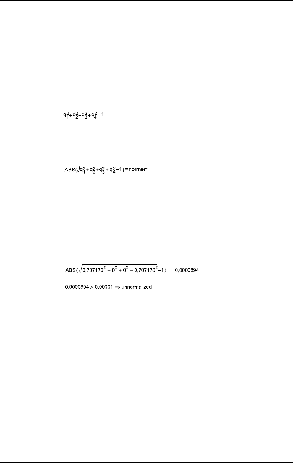
2 Functions
2.75. NOrient - Normalize orientation
RobotWare - OS
9013HAC 16581-1 Revision: J
© Copyright 2004-2010 ABB. All rights reserved.
2.75. NOrient - Normalize orientation
Usage
NOrient (Normalize Orientation) is used to normalize un-normalized orientation
(quaternion).
Description
An orientation must be normalized, i.e. the sum of the squares must equal 1:
.
If the orientation is slightly un-normalized, it is possible to normalize it. The normalization
error is the absolute value of the sum of the squares of the orientation components. The
orientation is considered to be slightly un-normalized if the normalization error is greater then
0.00001 and less then 0.1. If the normalization error is greater then 0.1 the orient is unusable.
.
normerr > 0.1 Unusable
normerr > 0.00001 AND normerr <= 0.1 Slightly un-normalized
normerr <= 0.00001 Normalized
Basic examples
Basic examples of the function
NOrient are illustrated below.
Example 1
We have a slightly un-normalized position (0.707170, 0, 0, 0.707170)
.
VAR orient unnormorient := [0.707170, 0, 0, 0.707170];
VAR orient normorient;
...
...
normorient := NOrient(unnormorient);
The normalization of the orientation ( 0.707170, 0, 0, 0.707170 ) becomes (0.707107, 0, 0,
0.707107).
Return value
Data type:
orient
The normalized orientation.
Continues on next page

2 Functions
2.75. NOrient - Normalize orientation
RobotWare - OS
3HAC 16581-1 Revision: J902
© Copyright 2004-2010 ABB. All rights reserved.
Arguments
NOrient (Rotation)
Rotation
Data type: orient
The orientation to be normalized.
Syntax
NOrient’(’
[Rotation ’:=’] <expression (IN) of orient>
’)’
A function with a return value of the data type orient.
Related information
For information about See
Mathematical instructions and functions Technical reference manual - RAPID
overview, section RAPID summary -
Mathematics
Continued

2 Functions
2.76. NumToDnum - Converts num to dnum
RobotWare - OS
9033HAC 16581-1 Revision: J
© Copyright 2004-2010 ABB. All rights reserved.
2.76. NumToDnum - Converts num to dnum
Usage
NumToDnum converts a num to a dnum.
Basic examples
A basic example of the function
NumToDnum is illustrated below.
Example 1
VAR num mynum:=55;
VAR dnum mydnum:=0;
mydnum:=NumToDnum(mynum);
The num value 55 is returned by the function as the dnum value 55.
Return value
Data type:
dnum
The return value of type dnum will have the same value as the input value of type num.
Arguments
NumToDnum (Value)
Value
Data type: num
The numeric value to be converted.
Syntax
NumToDnum
[ Value ’:=’ ] < expression (IN) of num > ’;’
A function with a return value of the data type dnum.
Related information
For information about See
Num data type num - Numeric values on page 1146
Dnum data type dnum - Double numeric values on page 1104

2 Functions
2.77. NumToStr - Converts numeric value to string
RobotWare - OS
3HAC 16581-1 Revision: J904
© Copyright 2004-2010 ABB. All rights reserved.
2.77. NumToStr - Converts numeric value to string
Usage
NumToStr (Numeric To String) is used to convert a numeric value to a string.
Basic examples
Basic examples of the function
NumToStr are illustrated below.
Example 1
VAR string str;
str := NumToStr(0.38521,3);
The variable str is given the value "0.385".
Example 2
reg1 := 0.38521;
str := NumToStr(reg1, 2\Exp);
The variable str is given the value "3.85E-01".
Example 3
VAR dnum ex3 := 1234567890.123456;
str := NumToStr(ex3, 15\Exp);
The variable str is given the value "1.234567890123456E+09".
Return value
Data type:
string
The numeric value converted to a string with the specified number of decimals, with exponent
if so requested. The numeric value is rounded if necessary. The decimal point is suppressed
if no decimals are included.
Arguments
NumToStr (Val | Dval Dec [\Exp])
Val
Va lue
Data type:
num
The numeric value to be converted.
Dval
Va lue
Data type:
dnum
The numeric value to be converted.
Dec
Decimals
Data type:
num
Number of decimals. The number of decimals must not be negative or greater than the
available precision for numeric values.
Continues on next page

2 Functions
2.77. NumToStr - Converts numeric value to string
RobotWare - OS
9053HAC 16581-1 Revision: J
© Copyright 2004-2010 ABB. All rights reserved.
[\Exp]
Exponent
Data type:
switch
To use exponent in return value.
Syntax
NumToStr’(’
[ Val ’:=’ ] <expression (IN) of num>
| [ Dval ’:=’ ] <expression (IN) of dnum> ’,’
[ Dec ’:=’ ] <expression (IN) of num>
[ \Exp ]
’)’
A function with a return value of the data type string.
Related information
For information about See
String functions Technical reference manual - RAPID overview, section
RAPID summary - String functions
Definition of string string - Strings on page 1195
String values Technical reference manual - RAPID overview, section
Basic characteristics - Basic elements
Continued

2 Functions
2.78. Offs - Displaces a robot position
RobotWare - OS
3HAC 16581-1 Revision: J906
© Copyright 2004-2010 ABB. All rights reserved.
2.78. Offs - Displaces a robot position
Usage
Offs is used to add an offset in the object coordinate system to a robot position.
Basic examples
Basic examples of the function
Offs are illustrated below.
See also More examples on page 907.
MoveL Offs(p2, 0, 0, 10), v1000, z50, tool1;
The robot is moved to a point 10 mm from the position p2 (in the z-direction).
p1 := Offs (p1, 5, 10, 15);
The robot position p1 is displaced 5 mm in the x-direction, 10 mm in the y-direction and 15
mm in the z-direction.
Return value
Data type:
robtarget
The displaced position data.
Arguments
Offs (Point XOffset YOffset ZOffset)
Point
Data type: robtarget
The position data to be displaced.
XOffset
Data type: num
The displacement in the x-direction, in the object coordinate system.
YOffset
Data type: num
The displacement in the y-direction, in the object coordinate system.
ZOffset
Data type: num
The displacement in the z-direction, in the object coordinate system.
Continues on next page
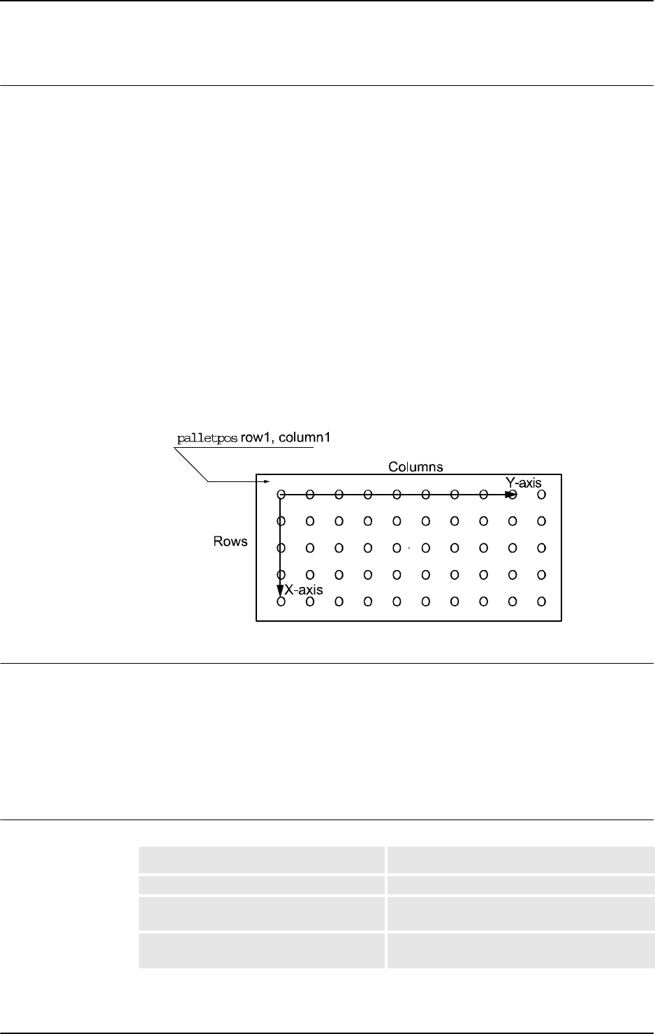
2 Functions
2.78. Offs - Displaces a robot position
RobotWare - OS
9073HAC 16581-1 Revision: J
© Copyright 2004-2010 ABB. All rights reserved.
More examples
More examples of the function
Offs are illustrated below.
Example 1
PROC pallet (num row, num column, num distance, PERS tooldata tool,
PERS wobjdata wobj)
VAR robtarget palletpos:=[[0, 0, 0], [1, 0, 0, 0], [0, 0, 0, 0],
[9E9, 9E9, 9E9, 9E9, 9E9, 9E9]];
palettpos := Offs (palettpos, (row-1)*distance, (column-
1)*distance, 0);
MoveL palettpos, v100, fine, tool\WObj:=wobj;
ENDPROC
A routine for picking parts from a pallet is made. Each pallet is defined as a work object (see
figure below). The part to be picked (row and column) and the distance between the parts are
given as input parameters. Incrementing the row and column index is performed outside the
routine.
The figure shows the position and orientation of the pallet is specified by defining a work
object.
xx0500002300
Syntax
Offs ’(’
[Point ’:=’] <expression (IN) of robtarget>’ ,’
[XOffset ’:=’] <expression (IN) of num> ’,’
[YOffset ’:=’] <expression (IN) of num> ’,’
[ZOffset ’:=’] <expression (IN) of num> ’)’
A function with a return value of the data type robtarget.
Related information
For information about See
Position data robtarget - Position data on page 1176
Mathematical instructions and functions Technical reference manual - RAPID overview,
section RAPID Summary - Mathematics
Positioning instructions Technical reference manual - RAPID overview,
section RAPID summary - Motion
Continued

2 Functions
2.79. OpMode - Read the operating mode
RobotWare - OS
3HAC 16581-1 Revision: J908
© Copyright 2004-2010 ABB. All rights reserved.
2.79. OpMode - Read the operating mode
Usage
OpMode(Operating Mode) is used to read the current operating mode of the system.
Basic examples
Basic examples of the function
OpMode are illustrated below.
Example 1
TEST OpMode()
CASE OP_AUTO:
...
CASE OP_MAN_PROG:
...
CASE OP_MAN_TEST:
...
DEFAULT:
...
ENDTEST
Different program sections are executed depending on the current operating mode.
Return value
Data type:
symnum
The current operating mode as defined in the table below.
Syntax
OpMode’(’ ’)’
A function with a return value of the data type symnum.
Related information
Return value Symbolic constant Comment
0 OP_UNDEF Undefined operating mode
1 OP_AUTO Automatic operating mode
2 OP_MAN_PROG Manual operating mode max. 250 mm/s
3 OP_MAN_TEST Manual operating mode full speed, 100 %
For information about See
Different operating modes Operating manual - IRC5 with FlexPendant
Reading running mode RunMode - Read the running mode on page 971

2 Functions
2.80. OrientZYX - Builds an orient from euler angles
RobotWare - OS
9093HAC 16581-1 Revision: J
© Copyright 2004-2010 ABB. All rights reserved.
2.80. OrientZYX - Builds an orient from euler angles
Usage
OrientZYX (Orient from Euler ZYX angles) is used to build an orient type variable out of
Euler angles.
Basic examples
Basic examples of the function
OrientZYX are illustrated below.
Example 1
VAR num anglex;
VAR num angley;
VAR num anglez;
VAR pose object;
...
object.rot := OrientZYX(anglez, angley, anglex)
Return value
Data type:
orient
The orientation made from the Euler angles.
The rotations will be performed in the following order:
• rotation around the z axis,
• rotation around the new y axis,
• rotation around the new x axis.
Arguments
OrientZYX (ZAngle YAngle XAngle)
ZAngle
Data type: num
The rotation, in degrees, around the Z axis.
YAngle
Data type: num
The rotation, in degrees, around the Y axis.
XAngle
Data type: num
The rotation, in degrees, around the X axis.
The rotations will be performed in the following order:
• rotation around the z axis,
• rotation around the new y axis,
• rotation around the new x axis.
Continues on next page

2 Functions
2.80. OrientZYX - Builds an orient from euler angles
RobotWare - OS
3HAC 16581-1 Revision: J910
© Copyright 2004-2010 ABB. All rights reserved.
Syntax
OrientZYX’(’
[ZAngle’:=’] <expression (IN) of num>’ ,’
[YAngle ’:=’] <expression (IN) of num> ’,’
[XAngle’:=’] <expression (IN) of num>
’)’
A function with a return value of the data type orient.
Related information
For information about See
Mathematical instructions and functions Operating manual - IRC5 with FlexPendant,
section RAPID summary - Mathematics
Continued

2 Functions
2.81. ORobT - Removes the program displacement from a position
RobotWare - OS
9113HAC 16581-1 Revision: J
© Copyright 2004-2010 ABB. All rights reserved.
2.81. ORobT - Removes the program displacement from a position
Usage
ORobT (Object Robot Target) is used to transform a robot position from the program
displacement coordinate system to the object coordinate system and/or to remove an offset
for the external axes.
Basic examples
Basic examples of the function
ORobT are illustrated below.
See also More examples on page 912.
Example 1
VAR robtarget p10;
VAR robtarget p11;
VAR num wobj_diameter;
p10 := CRobT(\Tool:=tool1 \WObj:=wobj_diameter);
p11 := ORobT(p10);
The current positions of the robot and the external axes are stored in p10 and p11. The values
stored in
p10 are related to the ProgDisp/ExtOffs coordinate system. The values stored in
p11 are related to the object coordinate system without any program displacement and any
offset on the external axes.
Return value
Data type:
robtarget
The transformed position data.
Arguments
ORobT (OrgPoint [\InPDisp] | [\InEOffs])
OrgPoint
Original Point
Data type:
robtarget
The original point to be transformed.
[\InPDisp]
In Program Displacement
Data type:
switch
Returns the TCP position in the ProgDisp coordinate system, i.e. removes external axes
offset only.
[\InEOffs]
In External Offset
Data type:
switch
Returns the external axes in the offset coordinate system, i.e. removes program displacement
for the robot only.
Continues on next page

2 Functions
2.81. ORobT - Removes the program displacement from a position
RobotWare - OS
3HAC 16581-1 Revision: J912
© Copyright 2004-2010 ABB. All rights reserved.
More examples
More examples of how to use the function
ORobT are illustrated below.
Example 1
p10 := ORobT(p10 \InEOffs );
The ORobT function will remove any program displacement that is active, leaving the TCP
position relative to the object coordinate system. The external axes will remain in the offset
coordinate system.
Example 2
p10 := ORobT(p10 \InPDisp );
The ORobT function will remove any offset of the external axes. The TCP position will
remain in the
ProgDisp coordinate system.
Syntax
ORobT ’(’
[ OrgPoint ’:=’ ] < expression (IN) of robtarget>
[’\’InPDisp] | [’\’InEOffs]’)’
A function with a return value of the data type robtarget.
Related information
For information about See
Definition of program displacement
for the robot
PDispOn - Activates program displacement on page
317
PDispSet - Activates program displacement using
known frame on page 321
Definition of offset for external axes EOffsOn - Activates an offset for external axes on page
88
EOffsSet - Activates an offset for external axes using
known values on page 90
Coordinate systems Operating manual - IRC5 with FlexPendant, section
Motion and I/O principles - Coordinate systems
Continued

2 Functions
2.82. ParIdPosValid - Valid robot position for parameter identification
RobotWare - OS
9133HAC 16581-1 Revision: J
© Copyright 2004-2010 ABB. All rights reserved.
2.82. ParIdPosValid - Valid robot position for parameter identification
Usage
ParIdPosValid (Parameter Identification Position Valid) checks whether the robot
position is valid for the current parameter identification, such as load identification of tool or
payload.
This instruction can only be used in the
main task or, if in a MultiMove system, in motion
tasks.
Basic examples
Basic examples of the function
ParIdPosValid are illustrated below.
Example 1
VAR jointtarget joints;
VAR bool valid_joints{12};
! Read the current joint angles
joints := CJointT();
! Check if valid robot position
IF ParIdPosValid (TOOL_LOAD_ID, joints, valid_joints) = TRUE THEN
! Valid position for load identification
! Continue with LoadId
...
ELSE
! Not valid position for one or several axes for load
! identification
! Move the robot to the output data given in variable joints
! and do ParIdPosValid once again
...
ENDIF
Check whether robot position is valid before doing load identification of tool.
Return value
Data type:
bool
TRUE
if robot position is valid for current parameter identification.
FALSE if robot position is not valid for current parameter identification.
Continues on next page

2 Functions
2.82. ParIdPosValid - Valid robot position for parameter identification
RobotWare - OS
3HAC 16581-1 Revision: J914
© Copyright 2004-2010 ABB. All rights reserved.
Arguments
ParIdPosValid (ParIdType Pos AxValid [\ConfAngle])
ParIdType
Data type: paridnum
Type of parameter identification as defined in table below
Pos
Data type: jointtarget
Variable specifies the actual joint angles for all robot and external axes. The variable is
updated by
ParIdPosValid according to the table below.
AxValid
Data type: bool
Array variable with 12 elements corresponding to 6 robot and 6 external axes. The variable
is updated by
ParIdPosValid according to the table below.
Value Symbolic constant Comment
1 TOOL_LOAD_ID Identify tool load
2 PAY_LOAD_ID Identify payload (Ref. instruction GripLoad)
3 IRBP_K Identify External Manipulator IRBP K load
4 IRBP_L Identify External Manipulator IRBP L load
4 IRBP_C Identify External Manipulator IRBP C load
4 IRBP_C_INDEX Identify External Manipulator IRBP C_INDEX load
4 IRBP_T Identify External Manipulator IRBP T load
5 IRBP_R Identify External Manipulator IRBP R load
6 IRBP_A Identify External Manipulator IRBP A load
6 IRBP_B Identify External Manipulator IRBP B load
6 IRBP_D Identify External Manipulator IRBP D load
Input axis joint value Output axis joint value
Valid Not changed
Not valid Changed to suitable value
Input axis joint value in Pos Output status in AxValid
Valid TRUE
Not valid FALSE
Continued
Continues on next page
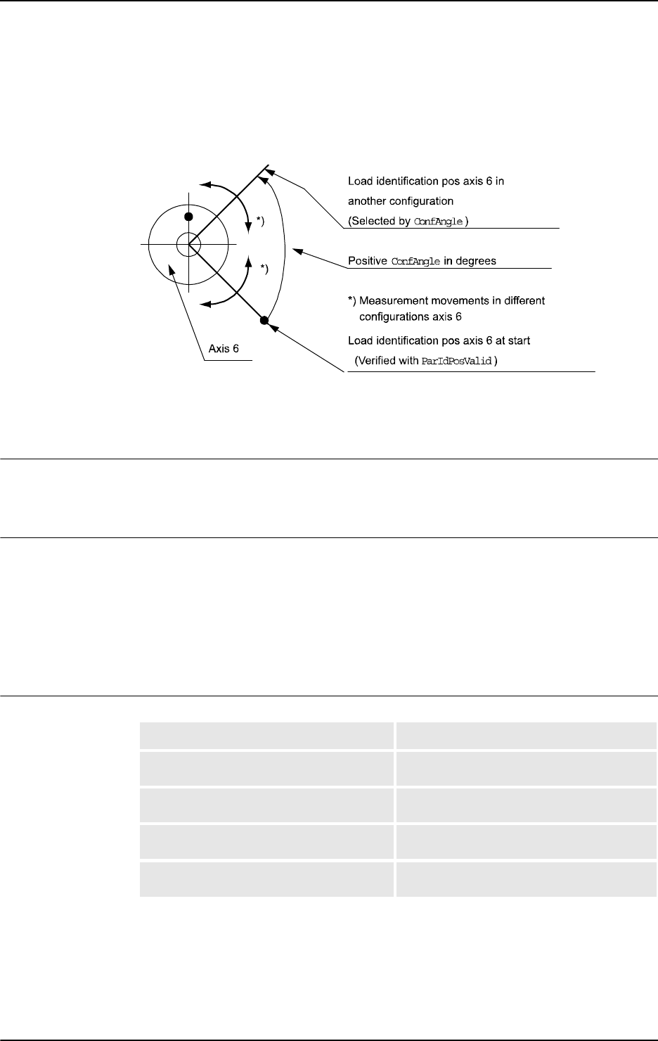
2 Functions
2.82. ParIdPosValid - Valid robot position for parameter identification
RobotWare - OS
9153HAC 16581-1 Revision: J
© Copyright 2004-2010 ABB. All rights reserved.
[ \ConfAngle ]
Data type: num
Option argument for specification of specific configuration angle +/- degrees to be used for
parameter identification.
xx0500002493
Default + 90 degrees if this argument is not specified.
Min. + or - 30 degrees. Optimum + or - 90 degrees.
Error handling
If an error occurs, the system variable
ERRNO is set to ERR_PID_RAISE_PP. This error can
then be handled in the error handler.
Syntax
ParIdPosValid’(’
[ ParIdType ´:=´ ] <expression (IN) of paridnum> ´,´
[ Pos ´:=´ ] <variable (VAR) of jointtarget> ´,´
[ AxValid ´:=´ ] <array variable {*} (VAR) of bool>
[ ´\´ ConfAngle ´:=´ <expression (IN) of num> ] ´)´
A function with a return value of the data type bool.
Related information
For information about See
Type of parameter identification paridnum - Type of parameter identification on
page 1154
Valid robot type ParIdRobValid - Valid robot type for
parameter identification on page 916
Load identification of tool or payload LoadId - Load identification of tool or payload
on page 212
Load identification of positioners (IRBP) ManLoadIdProc - Load identification of IRBP
manipulators on page 219
Continued

2 Functions
2.83. ParIdRobValid - Valid robot type for parameter identification
RobotWare - OS
3HAC 16581-1 Revision: J916
© Copyright 2004-2010 ABB. All rights reserved.
2.83. ParIdRobValid - Valid robot type for parameter identification
Usage
ParIdRobValid (Parameter Identification Robot Valid) checks whether the robot or
manipulator type is valid for the current parameter identification, such as load identification
of tool or payload.
This instruction can only be used in the main task
T_ROB1 or, if in a MultiMove system, in
Motion tasks.
Basic examples
Basic examples of the function
ParIdRobValue are illustrated below.
Example 1
TEST ParIdRobValid (TOOL_LOAD_ID)
CASE ROB_LOAD_VAL:
! Possible to do load identification of tool in actual robot
type
...
CASE ROB_LM1_LOAD_VAL:
! Only possible to do load identification of tool with
! IRB 6400FHD if actual load < 200 kg
...
CASE ROB_NOT_LOAD_VAL:
! Not possible to do load identification of tool in actual
robot type
...
ENDTEST
Return value
Data type:
paridvalidnum
Whether the specified parameter identification can be performed with the current robot or
manipulator type, as defined in the table below.
Value Symbolic constant Comment
10 ROB_LOAD_VAL Valid robot or manipulator type for the actual parameter
identification
11 ROB_NOT_LOAD_VAL Not valid type for the actual parameter identification
12 ROB_LM1_LOAD_VAL Valid robot type IRB 6400FHD for the actual parameter
identification if actual load < 200kg
Continues on next page

2 Functions
2.83. ParIdRobValid - Valid robot type for parameter identification
RobotWare - OS
9173HAC 16581-1 Revision: J
© Copyright 2004-2010 ABB. All rights reserved.
Arguments
ParIdRobValid(ParIdType [\MechUnit] [\AxisNo])
ParIdType
Data type: paridnum
Type of parameter identification as defined in table below.
[ \MechUnit ]
Mechanical Unit
Data type:
mecunit
Mechanical Unit used for the load identification. Only to be specified for external
manipulator. If this argument is omitted the TCP-robot in the task is used.
[ \AxisNo ]
Axis number
Data type:
num
Axis number within the mechanical unit which holds the load to be identified. Only to be
specified for external manipulator.
When the argument
\MechUnit is used, then \AxisNo must be used. The argument
\AxisNo can not be used without \MechUnit.
Error handling
If an error occurs, the system variable
ERRNO is set to ERR_PID_RAISE_PP. This error can
then be handled in the error handler.
Syntax
ParIdRobValid’(’
[ParIdType ’:=’] <expression (IN) of paridnum>
[´\’ MechUnit‘ :=’ <variable (VAR) of mecunit>]
[´\’ AxisNo ´:=’ <expression (IN) of num>] ´)’
A function with a return value of the data type paridvalidnum.
Value Symbolic constant Comment
1 TOOL_LOAD_ID Identify robot tool load
2 PAY_LOAD_ID Identify robot payload (Ref. instruction GripLoad)
3 IRBP_K Identify External Manipulator IRBP K load
4 IRBP_L Identify External Manipulator IRBP L load
4 IRBP_C Identify External Manipulator IRBP C load
4 IRBP_C_INDEX Identify External Manipulator IRBP C_INDEX load
4 IRBP_T Identify External Manipulator IRBP T load
5 IRBP_R Identify External Manipulator IRBP R load
6 IRBP_A Identify External Manipulator IRBP A load
6 IRBP_B Identify External Manipulator IRBP B load
6 IRBP_D Identify External Manipulator IRBP D load
Continued
Continues on next page

2 Functions
2.83. ParIdRobValid - Valid robot type for parameter identification
RobotWare - OS
3HAC 16581-1 Revision: J918
© Copyright 2004-2010 ABB. All rights reserved.
Related information
For information about See
Type of parameter identification paridnum - Type of parameter identification on
page 1154
Mechanical unit to be identified mecunit - Mechanical unit on page 1139
Result of this function paridvalidnum - Result of ParIdRobValid on
page 1156
Valid robot position ParIdPosValid - Valid robot position for
parameter identification on page 913
Load identification of robot tool load or
payload
LoadId - Load identification of tool or payload
on page 212
Load identification of positioner loads ManLoadIdProc - Load identification of IRBP
manipulators on page 219
Continued

2 Functions
2.84. PathLevel - Get current path level
RobotWare - OS
9193HAC 16581-1 Revision: J
© Copyright 2004-2010 ABB. All rights reserved.
2.84. PathLevel - Get current path level
Usage
PathLevel is used to get the current path level. This function will show whether the task is
executing on the original level or if the original movement path has been stored and a new
temporary movement is executing. Read more about Path Recovery in Application manual -
Motion functions and event.
Basic examples
Basic example of the function
PathLevel is illustrated below.
See also More examples on page 919.
Example 1
VAR num level;
level:= PathLevel();
Vari abl e level will be 1 if executed in an original movement path or 2 if executed in a
temporary new movement path.
Return value
Data type:
num
There are two possible return values.
More examples
One more example of how to use the function
PathLevel is illustrated below.
Example 1
...
MoveL p100, v100, z10, tool1;
StopMove;
StorePath;
p:= CRobT(\Tool:=tool1);
!New temporary movement
MoveL p1, v100, fine, tool1;
...
level:= PathLevel();
...
MoveL p, v100, fine, tool1;
RestoPath;
StartMove;
...
Vari abl e level will be 2.
Return value Description
1 Executing in original movement path.
2 Executing in StorePath level, a temporary new movement path.
Continues on next page

2 Functions
2.84. PathLevel - Get current path level
RobotWare - OS
3HAC 16581-1 Revision: J920
© Copyright 2004-2010 ABB. All rights reserved.
Limitations
RobotWare option Path Recovery must be installed to be able to use function
PathLevel at
path level 2
Syntax
PathLevel’(’’)’
A function with a return value of the data type num.
Related information
For information about See
Path recovery. Application manual - Motion functions and events
Store and restore path. StorePath - Stores the path when an interrupt occurs on page
521
RestoPath - Restores the path after an interrupt on page 362
Stop and start move. StartMove - Restarts robot movement on page 486
StopMove - Stops robot movement on page 515
Continued
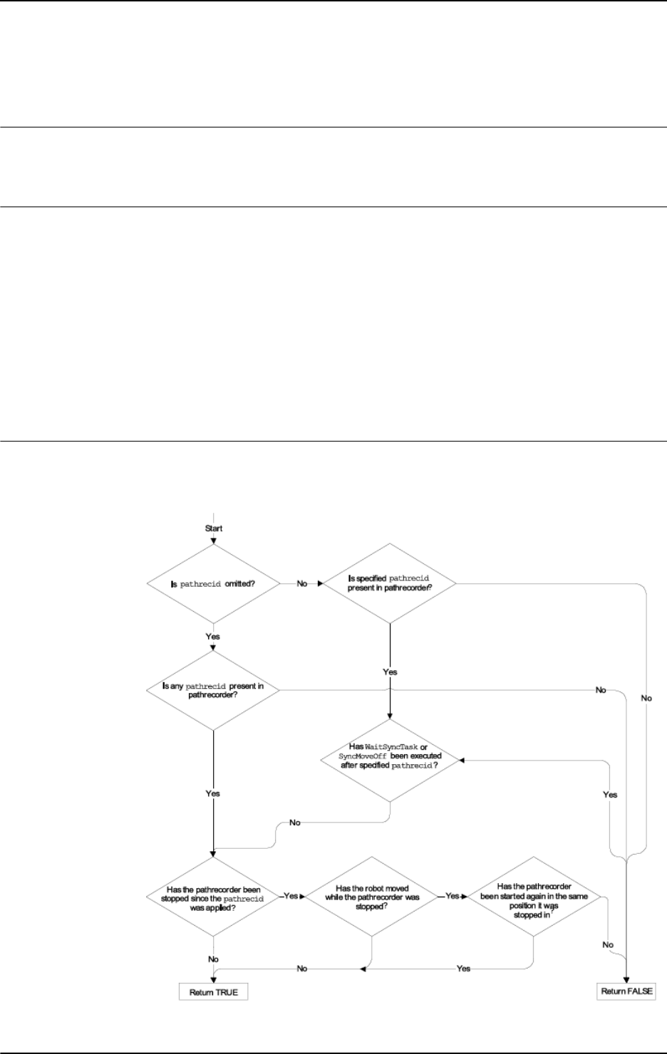
2 Functions
2.85. PathRecValidBwd - Is there a valid backward path recorded
Path Recovery
9213HAC 16581-1 Revision: J
© Copyright 2004-2010 ABB. All rights reserved.
2.85. PathRecValidBwd - Is there a valid backward path recorded
Usage
PathRecValidBwd is used to check if the path recorder is active and if a recorded backward
path is available.
Basic examples
Basic examples of the function
PathRecValidBwd are illustrated below.
See also More examples on page 922.
Example 1
VAR bool bwd_path;
VAR pathrecid fixture_id;
bwd_path := PathRecValidBwd (\ID:=fixture_id);
The variable bwd_path is set to TRUE if it is possible to back-up to the position with
identifier
fixture_id. If not, bwd_path is set to FALSE
Return value
Data type:
bool
The return value of the function can be determined from following flow chart:
xx0500002132
Continues on next page

2 Functions
2.85. PathRecValidBwd - Is there a valid backward path recorded
Path Recovery
3HAC 16581-1 Revision: J922
© Copyright 2004-2010 ABB. All rights reserved.
Arguments
PathRecValidBwd ([\ID])
[\ID]
Identifier
Data type:
pathrecid
Variable that specifies the name of the recording start position. Data type pathrecid is a
non-value type, only used as an identifier for naming the recording position.
Program execution
Before the path recorder is ordered to move backwards with
PathRecMoveBwd it is possible
to check whether a valid recorded path is present with
PathRecValidBwd.
More examples
More examples of how to use the function
PathRecValidBwd are illustrated below.
Example 1
PathRecStart id1;
MoveL p1, vmax, z50, tool1;
MoveL p2, vmax, z50, tool1;
bwd_path := PathRecValidBwd (\ID := id1);
The path recorder is started and two move instructions are executed. PathRecValidBwd will
return TRUE and the available backup path will be:
p2 -> p1 -> Start postion.
Example 2
PathRecStart id1;
MoveL p1, vmax, z50, tool1;
MoveL p2, vmax, z50, tool1;
PathRecStop \Clear;
bwd_path:= PathRecValidBwd (\ID := id1);
The path recorder is started and two move instructions are executed. Then the path recorder
is stopped and cleared.
PathRecValidBwd will return FALSE.
Example 3
PathRecStart id1;
MoveL p1, vmax, z50, tool1;
PathRecStart id2;
MoveL p2, vmax, z50, tool1;
bwd_path := PathRecValidBwd ();
The path recorder is started and one move instruction is executed. Then, an additional path
identifier is started followed by a move instruction.
PathRecValidBwd will return TRUE
and the backup path will be:
p2 -> p1.
Continued
Continues on next page

2 Functions
2.85. PathRecValidBwd - Is there a valid backward path recorded
Path Recovery
9233HAC 16581-1 Revision: J
© Copyright 2004-2010 ABB. All rights reserved.
Example 4
PathRecStart id1;
MoveL p1, vmax, z50, tool1;
WaitSyncTask sync101, tasklist_r1o1;
MoveL p2, vmax, z50, tool1;
bwd_path1 := PathRecValidBwd ();
bwd_path2 := PathRecValidBwd (\ID := id1);
Executing above program will result in that the boolean variable bwd_path1 will be assigned
TRUE since a valid backwards path to the
WaitSyncTask statement exists. The boolean
variable
bwd_path2 will be assigned FALSE since it isn’t possible to back up above a
WaitSyncTask statement.
Syntax
PathRecValidBwd ´(´
[´\´ ID‘ :=’ < variable (VAR) of pathrecid >] ’)’
A function with a return value of the data type bool.
Related information
For information about See
Path Recorder Identifiers pathrecid - Path recorder identifier on page
1158
Start - stop the path recorder PathRecStart - Start the path recorder on page
308
PathRecStop - Stop the path recorder on page
311
Play the path recorder backward PathRecMoveBwd - Move path recorder
backwards on page 298
Check if a valid forward path exists PathRecValidFwd - Is there a valid forward
path recorded on page 924
Play the path recorder forward PathRecMoveFwd - Move path recorder
forward on page 305
Motion in general Technical reference manual - RAPID overview,
section Motion and I/O principles
Continued

2 Functions
2.86. PathRecValidFwd - Is there a valid forward path recorded
Path Recovery
3HAC 16581-1 Revision: J924
© Copyright 2004-2010 ABB. All rights reserved.
2.86. PathRecValidFwd - Is there a valid forward path recorded
Usage
PathRecValidFwd is used to check if the path recorder can be used to move forward. The
ability to move forward with the path recorder implies that the path recorder must have been
ordered to move backwards earlier.
Basic examples
Basic examples of the function
PathRecValidFwd are illustrated below.
See also More examples on page 925.
Example 1
VAR bool fwd_path;
VAR pathrecid fixture_id;
fwd_path:= PathRecValidFwd (\ID:=fixture_id);
The variable fwd_path is set to TRUE if it is possible to move forward to the position with
the with identifier
fixture_id. If not, fwd_path is set to FALSE.
Return Value
Data type:
bool
The return value of PathRecValidFwd without specified \ID is:
TRUE if:
• The path recorder has moved the robot backwards, using PathRecMoveBwd.
• The robot has not moved away from the path executed by PathRecMoveBwd.
FALSE if:
• The above stated conditions are not met.
The return value of
PathRecValidFwd with specified \ID is:
TRUE if:
• The path recorder has moved the robot backwards, using PathRecMoveBwd.
• The robot has not moved away from the path executed by PathRecMoveBwd.
• The specified \ID was passed during the backward motion.
FALSE if:
• The above stated conditions are not met.
Arguments
PathRecValidFwd ([\ID])
[\ID]
Identifier
Data type:
pathrecid
Variable that specifies the name of the recording start position. Data type pathrecid is a
non-value type, only used as an identifier for naming the recording position.
Continues on next page

2 Functions
2.86. PathRecValidFwd - Is there a valid forward path recorded
Path Recovery
9253HAC 16581-1 Revision: J
© Copyright 2004-2010 ABB. All rights reserved.
Program execution
After the path recorder has been ordered to move backwards using
PathRecMoveBwd it is
possible to check if a valid recorded path to move the robot forward exists. If the identifier
\ID is omitted PathRevValidFwd returns if it is possible to move forward to the position
where the backwards movement was initiated.
More examples
More examples of how to use the function
PathRecValidFwd are illustrated below.
Example 1
VAR pathrecid id1;
VAR pathrecid id2;
VAR pathrecid id3;
PathRecStart id1;
MoveL p1, vmax, z50, tool1;
PathRecStart id2;
MoveL p2, vmax, z50, tool1;
PathRecStart id3;
!See figures 1 and 8 in tbe following table.
MoveL p3, vmax, z50, tool1;
ERROR
StorePath;
IF PathRecValidBwd(\ID:=id3) THEN
!See figure 2 in the following table.
PathRecMoveBwd \ID:=id3;
! Do some other operation
ENDIF
IF PathRecValidBwd(\ID:=id2) THEN
!See figure 3 in the following table.
PathRecMoveBwd \ID:=id2;
! Do some other operation
ENDIF
!See figure 4 in the following table.
PathRecMoveBwd;
! Do final service action
IF PathRecValidFwd(\ID:=id2) THEN
!See figure 5 in the following table.
PathRecMoveFwd \ID:=id2;
! Do some other operation
ENDIF
IF PathRecValidFwd(\ID:=id3) THEN
!See figure 6 in the following table.
PathRecMoveFwd \ID:=id3;
! Do some other operation
ENDIF
Continued
Continues on next page

2 Functions
2.86. PathRecValidFwd - Is there a valid forward path recorded
Path Recovery
3HAC 16581-1 Revision: J926
© Copyright 2004-2010 ABB. All rights reserved.
!See figure 7 in the following table.
PathRecMoveFwd;
RestoPath;
StartMove;
RETRY;
1
xx0500002121
2
xx0500002124
3
xx0500002126
4
xx0500002127
5
xx0500002128
6
xx0500002129
7
xx0500002138
Continued
Continues on next page

2 Functions
2.86. PathRecValidFwd - Is there a valid forward path recorded
Path Recovery
9273HAC 16581-1 Revision: J
© Copyright 2004-2010 ABB. All rights reserved.
The example above will start the path recorder and add identifiers at three different locations
along the executed path. The picture above references the example code and describes how
the robot will move in the case of an error while executing towards point
p3. The
PathRecValidBwd and PathRecValidFwd are used respectively as it is not possible in
advance to determine where in the program a possible error occurs.
Syntax
PathRecValidFwd ´(´
[´\’ ID‘:=’ < variable (VAR) of pathrecid >] ’)’
A function with a return value of the data type bool.
Related information
8
xx0500002131
For information about See
Path Recorder Identifiers pathrecid - Path recorder identifier on page 1158
Start - stop the path recorder PathRecStart - Start the path recorder on page
308
PathRecStop - Stop the path recorder on page 311
Check if valid backward path exists PathRecValidBwd - Is there a valid backward path
recorded on page 921
Play the path recorder backward PathRecMoveBwd - Move path recorder
backwards on page 298
Play the path recorder forward PathRecMoveFwd - Move path recorder forward
on page 305
Motion in general Technical reference manual - RAPID overview,
section Motion and I/O principles
Continued

2 Functions
2.87. PFRestart - Check interrupted path after power failure
RobotWare - OS
3HAC 16581-1 Revision: J928
© Copyright 2004-2010 ABB. All rights reserved.
2.87. PFRestart - Check interrupted path after power failure
Usage
PFRestart (Power Failure Restart) is used to check if the path has been interrupted at power
failure. If so it might be necessary to make some specific actions. The function checks the
path on current level, base level or on interrupt level.
Basic examples
Basic examples of the function
PFRestart are illustrated below.
Example 1
IF PFRestart() = TRUE THEN
It is checked, if an interrupted path exists on the current level. If so the function will return
TRUE.
Return value
Data type:
bool
TRUE
if an interrupted path exists on the specified path level, otherwise FALSE.
Arguments
PFRestart([\Base] | [\Irpt])
[ \Base ]
Base Level
Data type:
switch
Returns TRUE if an interrupted path exists on base level.
[ \Irpt ]
Interrupt Level
Data type:
switch
Returns TRUE if an interrupted path exists on StorePath level.
If no argument is given, the function will return
TRUE if an interrupted path exists on current
level.
Syntax
PFRestart’(’
[’\’Base] | [’\’Irpt]’)’
A function with a return value of the data type bool.
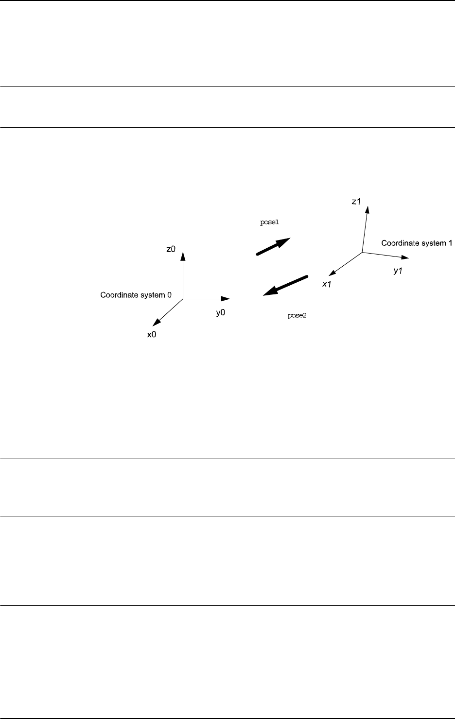
2 Functions
2.88. PoseInv - Inverts pose data
RobotWare - OS
9293HAC 16581-1 Revision: J
© Copyright 2004-2010 ABB. All rights reserved.
2.88. PoseInv - Inverts pose data
Usage
PoseInv (Pose Invert) calculates the reverse transformation of a pose.
Basic examples
Basic examples of the function
PoseInv are illustrated below.
Example 1
xx0500002443
Pose1 represents the coordinates system 1 related to the coordinate system 0. The
transformation giving the coordinate system 0 related to the coordinate system 1 is obtained
by the reverse transformation, stored in
pose2.
VAR pose pose1;
VAR pose pose2;
...
pose2 := PoseInv(pose1);
Return value
Data type:
pose
The value of the reverse pose.
Arguments
PoseInv (Pose)
Pose
Data type: pose
The pose to invert.
Syntax
PoseInv’(’
[Pose ’:=’] <expression (IN) of pose>
’)’
A function with a return value of the data type pose.
Continues on next page

2 Functions
2.88. PoseInv - Inverts pose data
RobotWare - OS
3HAC 16581-1 Revision: J930
© Copyright 2004-2010 ABB. All rights reserved.
Related information
For information about See
Mathematical instructions and functions Technical reference manual - RAPID
overview, section RAPID summary -
Mathematics
Continued
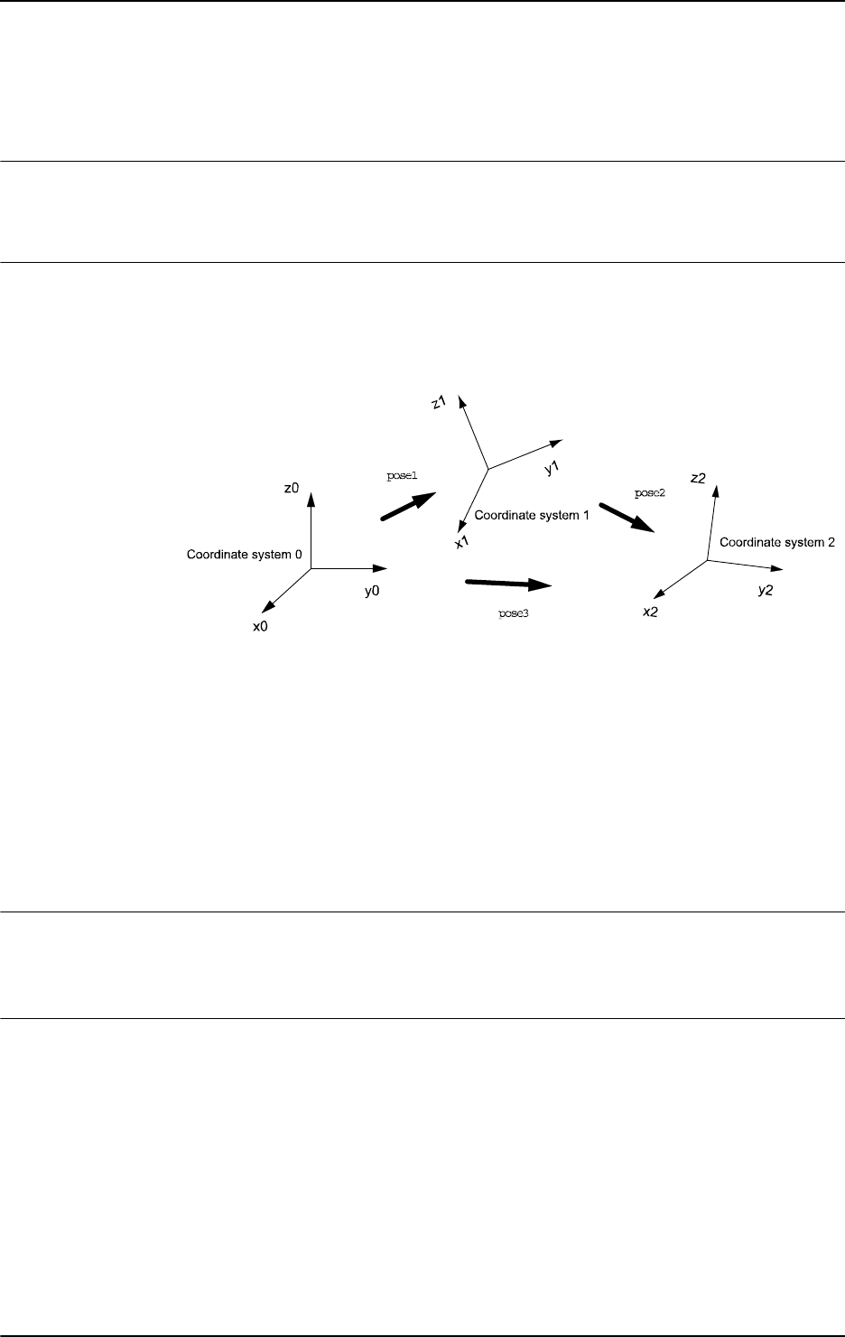
2 Functions
2.89. PoseMult - Multiplies pose data
RobotWare - OS
9313HAC 16581-1 Revision: J
© Copyright 2004-2010 ABB. All rights reserved.
2.89. PoseMult - Multiplies pose data
Usage
PoseMult (Pose Multiply) is used to calculate the product of two pose transformations. A
typical use is to calculate a new pose as the result of a displacement acting on an original pose.
Basic examples
Basic examples of the function
PoseMult are illustrated below.
Example 1
xx0500002444
pose1 represents the coordinate system 1 related to the coordinate system 0. pose2
represents the coordinate system 2 related to the coordinate system 1. The transformation
giving
pose3, the coordinate system 2 related to the coordinate system 0, is obtained by the
product of the two transformations:
VAR pose pose1;
VAR pose pose2;
VAR pose pose3;
...
pose3 := PoseMult(pose1, pose2);
Return value
Data type:
pose
The value of the product of the two poses.
Arguments
PoseMult (Pose1 Pose2)
Pose1
Data type: pose
The first pose.
Pose2
Data type: pose
The second pose.
Continues on next page

2 Functions
2.89. PoseMult - Multiplies pose data
RobotWare - OS
3HAC 16581-1 Revision: J932
© Copyright 2004-2010 ABB. All rights reserved.
Syntax
PoseMult’(’
[Pose1 ’:=’] <expression (IN) of pose>’,’
[Pose2 ’:=’] <expression (IN) of pose>
’)’
A function with a return value of the data type pose.
Related information
For information about See
Mathematical instructions and functions Technical reference manual - RAPID
overview, section RAPID summary -
Mathematics
Continued
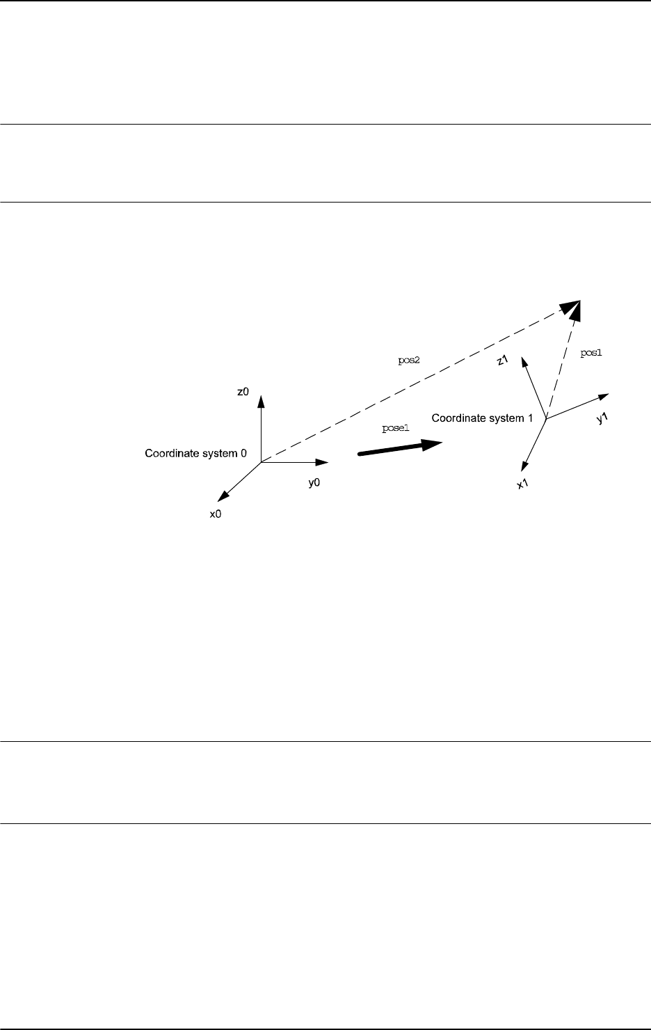
2 Functions
2.90. PoseVect - Applies a transformation to a vector
RobotWare - OS
9333HAC 16581-1 Revision: J
© Copyright 2004-2010 ABB. All rights reserved.
2.90. PoseVect - Applies a transformation to a vector
Usage
PoseVect (Pose Vector) is used to calculate the product of a pose and a vector. It is typically
used to calculate a vector as the result of the effect of a displacement on an original vector.
Basic examples
Basic examples of the function
PoseVect are illustrated below.
Example 1
xx0500002445
pose1 represents the coordinates system 1 related to the coordinate system 0.
pos1 is a vector related to coordinate system 1. The corresponding vector related to
coordinate system 0 is obtained by the product;
VAR pose pose1;
VAR pos pos1;
VAR pos pos2;
...
...
pos2:= PoseVect(pose1, pos1);
Return value
Data type:
pos
The value of the product of the pose and the original pos.
Arguments
PoseVect (Pose Pos)
Pose
Data type: pose
The transformation to be applied.
Pos
Data type: pos
The pos to be transformed.
Continues on next page

2 Functions
2.90. PoseVect - Applies a transformation to a vector
RobotWare - OS
3HAC 16581-1 Revision: J934
© Copyright 2004-2010 ABB. All rights reserved.
Syntax
PoseVect’(’
[Pose ’:=’] <expression (IN) of pose>’,’
[Pos ’:=’] <expression (IN) of pos>
’)’
A function with a return value of the data type pos.
Related information
For information about See
Mathematical instructions and functions Technical reference manual - RAPID
overview, section RAPID summary -
Mathematics
Continued

2 Functions
2.91. Pow - Calculates the power of a value
RobotWare - OS
9353HAC 16581-1 Revision: J
© Copyright 2004-2010 ABB. All rights reserved.
2.91. Pow - Calculates the power of a value
Usage
Pow (Power) is used to calculate the exponential value in any base.
Basic examples
Basic examples of the function
Pow are illustrated below.
Example 1
VAR num x;
VAR num y
VAR num reg1;
...
reg1:= Pow(x, y);
reg1
is assigned the value x
y
.
Return value
Data type:
num
The value of the Base raised to the power of the Exponent, i.e. Base
Exponent
.
Arguments
Pow (Base Exponent)
Base
Data type: num
The base argument value.
Exponent
Data type: num
The exponent argument value.
Limitations
The execution of the function x
y
will give an error if:
• x < 0 and y is not an integer;
• x = 0 and y ≤ 0.
Syntax
Pow’(’
[Base ’:=’] <expression (IN) of num>’,’
[Exponent ’:=’] <expression (IN) of num>
’)’
A function with a return value of the data type num.
Related information
For information about See
Mathematical instructions and functions Technical reference manual - RAPID overview,
section RAPID summary - Mathematics

2 Functions
2.92. PPMovedInManMode - Test whether the program pointer is moved in manual mode
RobotWare - OS
3HAC 16581-1 Revision: J936
© Copyright 2004-2010 ABB. All rights reserved.
2.92. PPMovedInManMode - Test whether the program pointer is moved in manual
mode
Usage
PPMovedInManMode returns TRUE if the user has moved the program pointer while the
controller is in manual mode - that is, operator key is at Man Reduced Speed or Man Full
Speed. The program pointer moved state is reset when the key is switched from Auto to Man,
or when using the instruction
ResetPPMoved.
Basic examples
Basic example of the function
PPMovedInManMode is illustrated below.
Example 1
IF PPMovedInManMode() THEN
WarnUserOfPPMovement;
DoJob;
ELSE
DoJob;
ENDIF
Return value
Data type:
bool
TRUE if the program pointer has been moved by the user while in manual mode.
Program execution
Test if the program pointer for the current program task has been moved in manual mode.
Syntax
PPMovedInManMode’(’’)’
A function with a return value of the data type bool.
Related information
For information about See
Test whether program pointer has moved IsStopStateEvent - Test whether moved
program pointer on page 886
Reset state of moved program pointer in
manual mode
ResetPPMoved - Reset state for the program
pointer moved in manual mode on page 360

2 Functions
2.93. Present - Tests if an optional parameter is used
RobotWare - OS
9373HAC 16581-1 Revision: J
© Copyright 2004-2010 ABB. All rights reserved.
2.93. Present - Tests if an optional parameter is used
Usage
Present is used to test if an optional argument has been used when calling a routine.
An optional parameter may not be used if it was not specified when calling the routine. This
function can be used to test if a parameter has been specified, in order to prevent errors from
occurring.
Basic examples
Basic examples of the function
Present are illustrated below.
See also More examples on page 938.
Example 1
PROC feeder (\switch on | \switch off)
IF Present (on) Set do1;
IF Present (off) Reset do1;
ENDPROC
The output do1, which controls a feeder, is set or reset depending on the argument used when
calling the routine.
Return value
Data type:
bool
TRUE = The parameter value or a switch has been defined when calling the routine.
FALSE = The parameter value or a switch has not been defined.
Arguments
Present (OptPar)
OptPar
Optional Parameter
Data type: Any type
The name of the optional parameter to be tested.
Continues on next page

2 Functions
2.93. Present - Tests if an optional parameter is used
RobotWare - OS
3HAC 16581-1 Revision: J938
© Copyright 2004-2010 ABB. All rights reserved.
More examples
More examples of how to use the function
Present are illustrated below.
Example 1
PROC glue (\switch on, num glueflow, robtarget topoint, speeddata
speed, zonedata zone, PERS tooldata tool, \PERS wobjdata
wobj)
IF Present (on) PulseDO glue_on;
SetAO gluesignal, glueflow;
IF Present (wobj) THEN
MoveL topoint, speed, zone, tool \WObj=wobj;
ELSE
MoveL topoint, speed, zone, tool;
ENDIF
ENDPROC
A glue routine is made. If the argument \on is specified when calling the routine, a pulse is
generated on the signal
glue_on. The robot then sets an analog output gluesignal, which
controls the glue gun, and moves to the end position. As the wobj parameter is optional,
different
MoveL instructions are used depending on whether this argument is used or not.
Syntax
Present ’(’
[OptPar’:=’] <reference (REF) of any type> ’)’
A REF parameter requires, in this case, the optional parameter name.
A function with a return value of the data type
bool.
Related information
For information about See
Routine parameters Technical reference manual - RAPID overview,
section Basic characteristics - Routines
Continued

2 Functions
2.94. ProgMemFree - Get the size of free program memory
RobotWare - OS
9393HAC 16581-1 Revision: J
© Copyright 2004-2010 ABB. All rights reserved.
2.94. ProgMemFree - Get the size of free program memory
Usage
ProgMemFree (Program Memory Free) is used to get the size of free program memory.
Basic examples
Basic examples of the function
ProgMemFree are illustrated below.
Example 1
FUNC num module_size(string file_path)
VAR num pgmfree_before;
VAR num pgmfree_after;
pgmfree_before:=ProgMemFree();
Load \Dynamic, file_path;
pgmfree_after:=ProgMemFree();
Unload file_path;
RETURN (pgmfree_before-pgmfree_after);
ENDFUNC
ProgMemFree
is used in a function that returns the value for how much memory a module
allocates in the program memory.
Return value
Data type:
num
The size of free program memory in bytes.
Syntax
ProgMemFree’(’ ’)’
A function with a return value of the data type num.
Related information
For information about See
Load a program module Load - Load a program module during execution on
page 208
Unload a program module UnLoad - UnLoad a program module during execution
on page 655

2 Functions
2.95. RawBytesLen - Get the length of rawbytes data
RobotWare - OS
3HAC 16581-1 Revision: J940
© Copyright 2004-2010 ABB. All rights reserved.
2.95. RawBytesLen - Get the length of rawbytes data
Usage
RawBytesLen is used to get the current length of valid bytes in a rawbytes variable.
Basic examples
Basic examples of the instruction
RawBytesLen are illustrated below.
Example 1
VAR rawbytes from_raw_data;
VAR rawbytes to_raw_data;
VAR num integer := 8
VAR num float := 13.4;
ClearRawBytes from_raw_data;
PackRawBytes integer, from_raw_data, 1 \IntX := INT;
PackRawBytes float, from_raw_data, (RawBytesLen(from_raw_data)+1)
\Float4;
CopyRawBytes from_raw_data, 1, to_raw_data, 3;
In this example the variable from_raw_data of type rawbytes is first cleared, i.e. all bytes
set to 0 (same as default at declaration). Then the value of integer is placed in the first 2 bytes
and with help of the function
RawBytesLen the value of float is placed in the next 4 bytes
(starting at index 3).
After having filled
from_raw_data with data, the contents (6 bytes) is copied to
to_raw_data, starting at position 3.
Return value
Data type:
num
The current length of valid bytes in a variable of type rawbytes; range 0 ... 1024.
In general, the current length of valid bytes in a rawbytes variable is updated by the system
to be the last written byte in the rawbytes structure.
For details, see data type
rawbytes, instruction ClearRawBytes, CopyRawBytes,
PackDNHeader, PackRawBytes and ReadRawBytes.
Arguments
RawBytesLen (RawData)
RawData
Data type: rawbytes
RawData
is the data container whose current length of valid bytes shall be returned.
Program execution
During program execution the current length of valid bytes is returned.
Continues on next page

2 Functions
2.95. RawBytesLen - Get the length of rawbytes data
RobotWare - OS
9413HAC 16581-1 Revision: J
© Copyright 2004-2010 ABB. All rights reserved.
Syntax
RawBytesLen ´(´
[RawData ´:=´ ] < variable (VAR) of rawbytes> ´)´
A function with a return value of the data type num.
Related information
For information about See
rawbytes data rawbytes - Raw data on page 1165
Clear the contents of rawbytes data ClearRawBytes - Clear the contents of
rawbytes data on page 49
Copy the contents of rawbytes data CopyRawBytes - Copy the contents of
rawbytes data on page 67
Pack DeviceNet header into rawbytes data PackDNHeader - Pack DeviceNet Header
into rawbytes data on page 287
Pack data into rawbytes data PackRawBytes - Pack data into rawbytes
data on page 290
Read rawbytes data ReadRawBytes - Read rawbytes data on
page 352
Unpack data from rawbytes data UnpackRawBytes - Unpack data from
rawbytes data on page 658
Write rawbytes data WriteRawBytes - Write rawbytes data on
page 725
Continued

2 Functions
2.96. ReadBin - Reads a byte from a file or serial channel
RobotWare - OS
3HAC 16581-1 Revision: J942
© Copyright 2004-2010 ABB. All rights reserved.
2.96. ReadBin - Reads a byte from a file or serial channel
Usage
ReadBin (Read Binary) is used to read a byte (8 bits) from a file or serial channel.
This function works on both binary and character-based files or serial channels.
Basic examples
Basic examples of the function
ReadBin are illustrated below.
See also More examples on page 943.
Example 1
VAR num character;
VAR iodev inchannel;
...
Open "com2:", inchannel\Bin;
character := ReadBin(inchannel);
A byte is read from the binary serial channel inchannel.
Return value
Data type:
num
A byte (8 bits) is read from a specified file or serial channel. This byte is converted to the
corresponding positive numeric value and returned as a
num data type. If a file is empty (end
of file),
EOF_BIN (the number -1) is returned.
Arguments
ReadBin (IODevice [\Time])
IODevice
Data type: iodev
The name (reference) of the file or serial channel to be read.
[\Time]
Data type: num
The max. time for the reading operation (timeout) in seconds. If this argument is not
specified, the max. time is set to 60 seconds. To wait forever, use the predefined constant
WAIT_MAX.
If this time runs out before the reading operation is finished, the error handler will be called
with the error code
ERR_DEV_MAXTIME. If there is no error handler, the execution will be
stopped.
The timeout function is in use also during program stop and will be noticed by the RAPID
program at program start.
Program execution
Program execution waits until a byte (8 bits) can be read from the file or serial channel.
Continues on next page

2 Functions
2.96. ReadBin - Reads a byte from a file or serial channel
RobotWare - OS
9433HAC 16581-1 Revision: J
© Copyright 2004-2010 ABB. All rights reserved.
More examples
More examples of the function
ReadBin are illustrated below.
Example 1
VAR num bindata;
VAR iodev file;
Open "HOME:/myfile.bin", file \Read \Bin;
bindata := ReadBin(file);
WHILE bindata <> EOF_BIN DO
TPWrite ByteToStr(bindata\Char);
bindata := ReadBin(file);
ENDWHILE
Read the contents of a binary file myfile.bin from the beginning to the end and displays the
received binary data converted to chars on the FlexPendant (one char on each line).
Limitations
The function can only be used for files and serial channels that have been opened with read
access (
\Read for character based files, \Bin or \Append \Bin for binary files).
Error handling
If an error occurs during reading, the system variable
ERRNO is set to ERR_FILEACC.
If time out before the read operation is finished, the system variable ERRNO is set to
ERR_DEV_MAXTIME.
These errors can then be dealt with by the error handler.
Predefined data
The constant
EOF_BIN can be used to stop reading at the end of the file.
CONST num EOF_BIN := -1;
Syntax
ReadBin’(’
[IODevice ’:=’] <variable (VAR) of iodev>
[’\’Time’:=’ <expression (IN) of num>]’)’
A function with a return value of the type num.
Related information
For information about See
Opening, etc. files or serial channels Technical reference manual - RAPID overview,
section RAPID summary - Communication
Convert a byte to a string data ByteToStr - Converts a byte to a string data on page
784
Continued

2 Functions
2.97. ReadDir - Read next entry in a directory
RobotWare - OS
3HAC 16581-1 Revision: J944
© Copyright 2004-2010 ABB. All rights reserved.
2.97. ReadDir - Read next entry in a directory
Usage
ReadDir is used to retrieve the name of the next file or subdirectory under a directory that
has been opened with the instruction
OpenDir.
As long as the function returns
TRUE, there can be more files or subdirectories to retrieve.
Basic examples
Basic examples of the function
ReadDir are illustrated below.
See also More examples on page 945.
Example 1
PROC lsdir(string dirname)
VAR dir directory;
VAR string filename;
OpenDir directory, dirname;
WHILE ReadDir(directory, filename) DO
TPWrite filename;
ENDWHILE
CloseDir directory;
ENDPROC
This example prints out the names of all files or subdirectories under the specified directory.
Return value
Data type:
bool
The function will return TRUE if it has retrieved a name, otherwise FALSE.
Arguments
ReadDir (Dev FileName)
Dev
Data type: dir
A variable with reference to the directory, fetched by instruction OpenDir.
FileName
Data type: string
The retrieved file or subdirectory name.
Program execution
This function returns a bool that specifies if the retrieving of a name was successful or not.
Continues on next page

2 Functions
2.97. ReadDir - Read next entry in a directory
RobotWare - OS
9453HAC 16581-1 Revision: J
© Copyright 2004-2010 ABB. All rights reserved.
More examples
More examples of the function
ReadDir are illustrated below
Example 1
This example implements a generic traverse of a directory structure function.
PROC searchdir(string dirname, string actionproc)
VAR dir directory;
VAR string filename;
IF IsFile(dirname \Directory) THEN
OpenDir directory, dirname;
WHILE ReadDir(directory, filename) DO
! .. and . is the parent and resp. this directory
IF filename <> ".." AND filename <> "." THEN
searchdir dirname+"/"+filename, actionproc;
ENDIF
ENDWHILE
CloseDir directory;
ELSE
%actionproc% dirname;
ENDIF
ERROR
RAISE;
ENDPROC
PROC listfile(string filename)
TPWrite filename;
ENDPROC
PROC main()
! Execute the listfile routine for all files found under the
! tree in HOME:
searchdir "HOME:","listfile";
ENDPROC
This program traverses the directory structure under "HOME:", and for each file found it calls
the
listfile procedure. The searchdir is the generic part that knows nothing about the
start of the search or which routine should be called for each file. It uses
IsFile to check
whether it has found a subdirectory or a file and it uses the late binding mechanism to call the
procedure specified in
actionproc for all files found. The actionproc routine should be
a procedure with one parameter of the type
string.
Error handling
If the directory is not opened (see
OpenDir), the system variable ERRNO is set to
ERR_FILEACC. This error can then be handled in the error handler.
Continued
Continues on next page

2 Functions
2.97. ReadDir - Read next entry in a directory
RobotWare - OS
3HAC 16581-1 Revision: J946
© Copyright 2004-2010 ABB. All rights reserved.
Syntax
ReadDir ’(’
[ Dev’:=’ ] < variable (VAR) of dir>’,’
[ FileName’:=’ ] < var or pers (INOUT) of string>´)´
A function with a return value of the data type bool.
Related information
For information about See
Directory dir - File directory structure on page 1103
Make a directory MakeDir - Create a new directory on page 218
Open a directory OpenDir - Open a directory on page 285
Close a directory CloseDir - Close a directory on page 56
Remove a directory RemoveDir - Delete a directory on page 355
Remove a file RemoveFile - Delete a file on page 356
Rename a file RenameFile - Rename a file on page 357
Continued

2 Functions
2.98. ReadMotor - Reads the current motor angles
RobotWare - OS
9473HAC 16581-1 Revision: J
© Copyright 2004-2010 ABB. All rights reserved.
2.98. ReadMotor - Reads the current motor angles
Usage
ReadMotor is used to read the current angles of the different motors of the robot and external
axes. The primary use of this function is in the calibration procedure of the robot.
Basic examples
Basic example of the function
ReadMotor is illustrated below.
See also More examples on page 947.
VAR num motor_angle2;
motor_angle2 := ReadMotor(2);
The current motor angle of the second axis of the robot is stored in motor_angle2.
Return value
Data type:
num
The current motor angle in radians of the stated axis of the robot or external axes.
Arguments
ReadMotor [\MecUnit ] Axis
MecUnit
Mechanical Unit
Data type:
mecunit
The name of the mechanical unit for which an axis is to be read. If this argument is omitted,
the axis for the connected robot is read.
Axis
Data type: num
The number of the axis to be read (1 - 6).
Program execution
The motor angle returned represents the current position in radians for the motor without any
calibration offset. The value is not related to a fix position of the robot, only to the resolver
internal zero position, i.e. normally the resolver zero position closest to the calibration
position (the difference between the resolver zero position and the calibration position is the
calibration offset value). The value represents the full movement of each axis, although this
may be several turns.
More examples
More examples of the function
ReadMotor are illustrated below.
Example 1
VAR num motor_angle3;
motor_angle3 := ReadMotor(\MecUnit:=ROB_1, 3);
The current motor angle of the third axis of the robot ROB_1 is stored in motor_angle3.
Continues on next page

2 Functions
2.98. ReadMotor - Reads the current motor angles
RobotWare - OS
3HAC 16581-1 Revision: J948
© Copyright 2004-2010 ABB. All rights reserved.
Syntax
ReadMotor’(’
[’\’MecUnit ’:=’ < variable (VAR) of mecunit>’,’]
[Axis’ :=’ ] < expression (IN) of num> ’)’
A function with a return value of the data type num.
Related information
For information about See
Reading the current joint angle CJointT - Reads the current joint angles on
page 800
Continued

2 Functions
2.99. ReadNum - Reads a number from a file or serial channel
RobotWare - OS
9493HAC 16581-1 Revision: J
© Copyright 2004-2010 ABB. All rights reserved.
2.99. ReadNum - Reads a number from a file or serial channel
Usage
ReadNum (Read Numeric) is used to read a number from a character-based file or serial
channel.
Basic examples
Basic examples of the function
ReadNum are illustrated below.
See also More examples on page 950.
Example 1
VAR iodev infile;
...
Open "HOME:/file.doc", infile\Read;
reg1 := ReadNum(infile);
reg1
is assigned a number read from the file file.doc.
Return value
Data type:
num
The numeric value read from a specified file or serial channel. If the file is empty (end of file),
the number
EOF_NUM (9.998E36) is returned.
Arguments
ReadNum (IODevice [\Delim] [\Time])
IODevice
Data type: iodev
The name (reference) of the file or serial channel to be read.
[\Delim]
Delimiters
Data type:
string
A string containing the delimiters to use when parsing a line in the file or serial channel. By
default (without
\Delim), the file is read line by line and the line-feed character (\0A) is the
only delimiter considered by the parsing. When the
\Delim argument is used, any character
in the specified string argument will be considered to determine the significant part of the
line.
When using the argument
\Delim, the control system always adds the characters carriage
return (
\0D) and line-feed (\0A) to the delimiters specified by the user.
To specify non-alphanumeric characters, use
\xx, where xx is the hexadecimal
representation of the ASCII code of the character (example: TAB is specified by
\09).
Continues on next page

2 Functions
2.99. ReadNum - Reads a number from a file or serial channel
RobotWare - OS
3HAC 16581-1 Revision: J950
© Copyright 2004-2010 ABB. All rights reserved.
[\Time]
Data type: num
The max. time for the reading operation (timeout) in seconds. If this argument is not
specified, the max. time is set to 60 seconds. To wait forever, use the predefined constant
WAIT_MAX.
If this time runs out before the read operation is finished, the error handler will be called with
the error code
ERR_DEV_MAXTIME. If there is no error handler, the execution will be stopped.
The timeout function is also in use during program stop and will be noticed by the RAPID
program at program start.
Program execution
Starting at the current file position, the function reads and discards any heading delimiters. A
heading delimiter without the argument
\Delim is a line-feed character. Heading delimiters
with the argument \
Delim are any characters specified in the \Delim argument plus carriage
return and line-feed characters. It then reads everything up to and including the next delimiter
character (will be discarded), but not more than 80 characters. If the significant part exceeds
80 characters, the remainder of the characters will be read on the next reading.
The string that is read is then converted to a numeric value; e.g. "234.4" is converted to the
numeric value 234.4.
More examples
More examples of the function
ReadNum are illustrated below.
reg1 := ReadNum(infile\Delim:="\09");
IF reg1 > EOF_NUM THEN
TPWrite "The file is empty";
...
Reads a number in a line where numbers are separated by TAB ("\09") or SPACE (" ")
characters. Before using the number read from the file, a check is performed to make sure that
the file is not empty.
Limitations
The function can only be used for character based files that have been opened for reading.
Error handling
If an access error occurs during reading, the system variable
ERRNO is set to ERR_FILEACC.
If there is an attempt to read non-numeric data, the system variable
ERRNO is set to
ERR_RCVDATA.
If time out before the read operation is finished, the system variable
ERRNO is set to
ERR_DEV_MAXTIME.
These errors can then be dealt with by the error handler.
Predefined data
The constant
EOF_NUM can be used to stop reading, at the end of the file.
CONST num EOF_NUM := 9.998E36;
Continued
Continues on next page

2 Functions
2.99. ReadNum - Reads a number from a file or serial channel
RobotWare - OS
9513HAC 16581-1 Revision: J
© Copyright 2004-2010 ABB. All rights reserved.
Syntax
ReadNum ’(’
[IODevice ’:=’]<variable (VAR) of iodev>
[’\’Delim’:=’<expression (IN) of string>]
[’\’Time’:=’<expression (IN) of num>]’)’
A function with a return value of the type num.
Related information
For information about See
Opening, etc. files or serial channels Technical reference manual - RAPID overview,
section RAPID summary - Communication
Continued

2 Functions
2.100. ReadStr - Reads a string from a file or serial channel
RobotWare - OS
3HAC 16581-1 Revision: J952
© Copyright 2004-2010 ABB. All rights reserved.
2.100. ReadStr - Reads a string from a file or serial channel
Usage
ReadStr (Read String) is used to read a string from a character-based file or serial channel.
Basic examples
Basic examples of the function
ReadStr are illustrated below.
See also More examples on page 953.
Example 1
VAR string text;
VAR iodev infile;
...
Open "HOME:/file.doc", infile\Read;
text := ReadStr(infile);
text
is assigned a string read from the file file.doc.
Return value
Data type:
string
The string read from the specified file or serial channel. If the file is empty (end of file), the
string
"EOF" is returned.
Arguments
ReadStr (IODevice [\Delim] [\RemoveCR] [\DiscardHeaders]
[\Time])
IODevice
Data type: iodev
The name (reference) of the file or serial channel to be read.
[\Delim]
Delimiters
Data type:
string
A string containing the delimiters to use when parsing a line in the file or serial channel. By
default the file is read line by line and the line-feed character (\0A) is the only delimiter
considered by the parsing. When the
\Delim argument is used, any character in the specified
string argument plus by default line-feed character will be considered to determine the
significant part of the line.
To specify non-alphanumeric characters, use \
xx, where xx is the hexadecimal representation
of the ASCII code of the character (example: TAB is specified by \
09).
[\RemoveCR]
Data type: switch
A switch used to remove the trailing carriage return character when reading PC files. In PC
files, a new line is specified by carriage return and line feed (CRLF). When reading a line in
such files, the carriage return character is by default read into the return string. When using
this argument, the carriage return character will be read from the file but not included in the
return string.
Continues on next page

2 Functions
2.100. ReadStr - Reads a string from a file or serial channel
RobotWare - OS
9533HAC 16581-1 Revision: J
© Copyright 2004-2010 ABB. All rights reserved.
[\DiscardHeaders]
Data type: switch
This argument specifies whether the heading delimiters (specified in \Delim plus default
line-feed) are skipped or not before transferring data to the return string. By default, if the first
character at the current file position is a delimiter, it is read but not transferred to the return
string, the line parsing is stopped and the return will be an empty string. If this argument is
used, all delimiters included in the line will be read from the file but discarded, and no return
will be done until the return string will contain the data starting at the first non-delimiter
character in the line.
[\Time]
Data type: num
The max. time for the reading operation (timeout) in seconds. If this argument is not
specified, the max. time is set to 60 seconds. To wait forever, use the predefined constant
WAIT_MAX.
If this time runs out before the read operation is finished, the error handler will be called with
the error code
ERR_DEV_MAXTIME. If there is no error handler, the execution will be stopped.
The timeout function is in use also during program stop and will be noticed in the RAPID
program at program start.
Program execution
Starting at the current file position, if the
\DiscardHeaders argument is used, the function
reads and discards any heading delimiters (line-feed characters and any character specified in
the
\Delim argument). In all cases, it then reads everything up to the next delimiter character,
but not more than 80 characters. If the significant part exceeds 80 characters, the remainder
of the characters will be read on the next reading. The delimiter that caused the parsing to stop
is read from the file but not transferred to the return string. If the last character in the string is
a carriage return character and the
\RemoveCR argument is used, this character will be
removed from the string.
More examples
More examples of the function
ReadStr are illustrated below.
Example 1
text := ReadStr(infile);
IF text = EOF THEN
TPWrite "The file is empty";
...
Before using the string read from the file, a check is performed to make sure that the file is
not empty.
Continued
Continues on next page

2 Functions
2.100. ReadStr - Reads a string from a file or serial channel
RobotWare - OS
3HAC 16581-1 Revision: J954
© Copyright 2004-2010 ABB. All rights reserved.
Example 2
Consider a file containing:
<LF><SPACE><TAB>Hello<SPACE><SPACE>World<CR><LF>
text := ReadStr(infile);
text
will be an empty string: the first character in the file is the default <LF> delimiter.
text := ReadStr(infile\DiscardHeaders);
text will contain <SPACE><TAB>Hello<SPACE><SPACE>World<CR>: the first character in
the file, the default
<LF> delimiter, is discarded.
text := ReadStr(infile\RemoveCR\DiscardHeaders);
text
will contain <SPACE><TAB>Hello<SPACE><SPACE>World: the first character in the
file, the default <LF> delimiter, is discarded; the final carriage return character is removed
text := ReadStr(infile\Delim:=" \09"\RemoveCR\DiscardHeaders);
text will contain "Hello": the first characters in the file that match either the default <LF>
delimiter or the character set defined by
\Delim (space and tab) are discarded. Data is then
transferred up to the first delimiter that is read from the file but not transferred into the string.
A new invocation of the same statement will return
"World".
Example 3
Consider a file containing:
<CR><LF>Hello<CR><LF>
text := ReadStr(infile);
text
will contain the <CR> (\0d) character: <CR> and <LF> characters are read from the
file, but only
<CR> is transferred to the string. A new invocation of the same statement will
return
"Hello\0d".
text := ReadStr(infile\RemoveCR);
text
will contain an empty string: <CR> and <LF> characters are read from the file; <CR> is
transferred but removed from the string. A new invocation of the same statement will return
"Hello".
text := ReadStr(infile\Delim:="\0d");
text
will contain an empty string: <CR> is read from the file but not transferred to the return
string. A new invocation of the same instruction will return an empty string again:
<LF> is
read from the file but not transferred to the return string.
text := ReadStr(infile\Delim:="\0d"\DiscardHeaders);
text
will contain "Hello". A new invocation of the same instruction will return "EOF" (end
of file).
Continued
Continues on next page

2 Functions
2.100. ReadStr - Reads a string from a file or serial channel
RobotWare - OS
9553HAC 16581-1 Revision: J
© Copyright 2004-2010 ABB. All rights reserved.
Limitations
The function can only be used for files or serial channels that have been opened for reading
in a character-based mode.
Error handling
If an error occurs during reading, the system variable
ERRNO is set to ERR_FILEACC.
If timeout before the read operation is finished, the system variable
ERRNO is set to
ERR_DEV_MAXTIME.
These errors can then be dealt with by the error handler.
Predefined data
The constant
EOF can be used to check if the file was empty when trying to read from the file
or to stop reading at the end of the file.
CONST string EOF := "EOF";
Syntax
ReadStr ’(’
[IODevice’ :=’] <variable (VAR) of iodev>
[’\’Delim’ :=’<expression (IN) of string>]
[’\’RemoveCR]
[’\’DiscardHeaders]
[’\’Time’:=’ <expression (IN) of num>]’)’
A function with a return value of the type string.
Related information
For information about See
Opening, etc. files or serial channels Technical reference manual - RAPID overview,
section RAPID summary - Communication
Continued

2 Functions
2.101. ReadStrBin - Reads a string from a binary serial channel or file
RobotWare - OS
3HAC 16581-1 Revision: J956
© Copyright 2004-2010 ABB. All rights reserved.
2.101. ReadStrBin - Reads a string from a binary serial channel or file
Usage
ReadStrBin (Read String Binary) is used to read a string from a binary serial channel or file.
Basic examples
Basic examples of the function
ReadStrBin are illustrated below.
Example 1
VAR iodev channel2;
VAR string text;
...
Open "com2:", channel2 \Bin;
text := ReadStrBin (channel2, 10);
text := ReadStrBin(infile,20);
IF text = EOF THEN
text
is assigned a 10 characters text string read from the serial channel referred to by
channel2
Before using the string read from the file, a check is performed to make sure that the file is
not empty.
Return value
Data type:
string
The text string read from the specified serial channel or file. If the file is empty (end of file),
the string
"EOF" is returned.
Arguments
ReadStrBin (IODevice NoOfChars [\Time])
IODevice
Data type: iodev
The name (reference) of the binary serial channel or file to be read.
NoOfChars
Number of Characters
Data type:
num
The number of characters to be read from the binary serial channel or file.
[\Time]
Data type: num
The max. time for the reading operation (timeout) in seconds. If this argument is not
specified, the max. time is set to 60 seconds. To wait forever, use the predefined constant
WAIT_MAX.
If this time runs out before the read operation is finished, the error handler will be called with
the error code
ERR_DEV_MAXTIME. If there is no error handler, the execution will be stopped.
The timeout function is in use also during program stop and will be noticed by the RAPID
program at program start.
Continues on next page

2 Functions
2.101. ReadStrBin - Reads a string from a binary serial channel or file
RobotWare - OS
9573HAC 16581-1 Revision: J
© Copyright 2004-2010 ABB. All rights reserved.
Program execution
The function reads the specified number of characters from the binary serial channel or file.
Limitations
The function can only be used for serial channels or files that have been opened for reading
in a binary mode.
Error handling
If an error occurs during reading, the system variable
ERRNO is set to ERR_FILEACC.
If timeout before the read operation is finished, the system variable
ERRNO is set to
ERR_DEV_MAXTIME.
These errors can then be dealt with by the error handler.
Predefined data
The constant
EOF can be used to check if the file was empty, when trying to read from the file
or to stop reading at the end of the file.
CONST string EOF := "EOF";
Syntax
ReadStrBin ’(’
[IODevice ’:=’] <variable (VAR) of iodev>’,’
[NoOfChars’ :=’] <expression (IN) of num>
[’\’Time ’:=’ <expression (IN) of num>]’)’
A function with a return value of the type string.
Related information
For information about See
Opening, etc. serial channels or files Technical reference manual - RAPID overview,
section RAPID summary - Communication
Write binary string WriteStrBin - Writes a string to a binary serial
channel on page 727
Continued

2 Functions
2.102. ReadVar - Read variable from a device
Sensor Interface
3HAC 16581-1 Revision: J958
© Copyright 2004-2010 ABB. All rights reserved.
2.102. ReadVar - Read variable from a device
Usage
ReadVar is used to read a variable from a device connected to the serial sensor interface.
The sensor interface communicates with sensors over serial channels using the RTP1
transport protocol.
This is an example of a sensor channel configuration.
COM_PHY_CHANNEL:
• Name “COM1:”
• Connector “COM1”
• Baudrate 19200
COM_TRP:
• Name “sen1:”
• Type “RTP1”
• PhyChannel “COM1”
Basic examples
Basic examples of the function
ReadVar are illustrated below.
Example 1
CONST num XCoord := 8;
CONST num YCoord := 9;
CONST num ZCoord := 10;
VAR pos SensorPos;
! Connect to the sensor device "sen1:" (defined in sio.cfg).
SenDevice "sen1:";
! Read a cartesian position from the sensor.
SensorPos.x := ReadVar ("sen1:", XCoord);
SensorPos.y := ReadVar ("sen1:", YCoord);
SensorPos.z := ReadVar ("sen1:", ZCoord);
Continues on next page

2 Functions
2.102. ReadVar - Read variable from a device
Sensor Interface
9593HAC 16581-1 Revision: J
© Copyright 2004-2010 ABB. All rights reserved.
Arguments
ReadVar (device, VarNo, [ \TaskName ])
device
Data type: string
The I/O device name configured in sio.cfg for the sensor used.
VarNo
Data type: num
The argument VarNo is used to select variable to be read.
[ \TaskName ]
Data type: string
The argument TaskName makes it possible to access devices in other RAPID tasks.
Fault management
Syntax
ReadVar
[ device ‘:=’ ] < expression(IN) of string>’,’
[ VarNo ’:=’ ] < expression (IN) of num > ‘,’
[ ’\’ TaskName’ :=’ < expression (IN) of string > ] ‘;’
A function with a return value of the data type num.
Error constant (ERRNO value) Description
SEN_NO_MEAS Measurement failure
SEN_NOREADY Sensor unable to handle command
SEN_GENERRO General sensor error
SEN_BUSY Sensor busy
SEN_UNKNOWN Unknown sensor
SEN_EXALARM External sensor error
SEN_CAALARM Internal sensor error
SEN_TEMP Sensor temperature error
SEN_VALUE Illegal communication value
SEN_CAMCHECK Sensor check failure
SEN_TIMEOUT Communication error
Continued
Continues on next page

2 Functions
2.102. ReadVar - Read variable from a device
Sensor Interface
3HAC 16581-1 Revision: J960
© Copyright 2004-2010 ABB. All rights reserved.
Related information
For information about See
Connect to a sensor device SenDevice - connect to a sensor device on page
425
Write a sensor variable WriteVar - write variable on page 729
Write a sensor data block WriteBlock - write block of data to device on
page 719
Read a sensor data block ReadBlock - read a block of data from device on
page 343
Configuration of sensor communication Technical reference manual - RAPID overview,
section Communication
Continued

2 Functions
2.103. RelTool - Make a displacement relative to the tool
RobotWare - OS
9613HAC 16581-1 Revision: J
© Copyright 2004-2010 ABB. All rights reserved.
2.103. RelTool - Make a displacement relative to the tool
Usage
RelTool (Relative Tool) is used to add a displacement and/or a rotation, expressed in the
active tool coordinate system, to a robot position.
Basic examples
Basic examples of the function
RelTool are illustrated below.
Example 1
MoveL RelTool (p1, 0, 0, 100), v100, fine, tool1;
The robot is moved to a position that is 100 mm from p1 in the z direction of the tool.
Example 2
MoveL RelTool (p1, 0, 0, 0 \Rz:= 25), v100, fine, tool1;
The tool is rotated 25° around its z-axis.
Return value
Data type:
robtarget
The new position with the addition of a displacement and/or a rotation, if any, relative to the
active tool.
Arguments
RelTool (Point Dx Dy Dz [\Rx] [\Ry] [\Rz])
Point
Data type: robtarget
The input robot position. The orientation part of this position defines the current orientation
of the tool coordinate system.
Dx
Data type: num
The displacement in mm in the x direction of the tool coordinate system.
Dy
Data type: num
The displacement in mm in the y direction of the tool coordinate system.
Dz
Data type: num
The displacement in mm in the z direction of the tool coordinate system.
[\Rx]
Data type: num
The rotation in degrees around the x axis of the tool coordinate system.
[\Ry]
Data type: num
The rotation in degrees around the y axis of the tool coordinate system.
Continues on next page

2 Functions
2.103. RelTool - Make a displacement relative to the tool
RobotWare - OS
3HAC 16581-1 Revision: J962
© Copyright 2004-2010 ABB. All rights reserved.
[\Rz]
Data type: num
The rotation in degrees around the z axis of the tool coordinate system.
If two or three rotations are specified at the same time, these will be performed first around
the x-axis, then around the new y-axis, and then around the new z-axis.
Syntax
RelTool’(’
[ Point ’:=’ ] < expression (IN) of robtarget>’,’
[Dx ’:=’] <expression (IN) of num>’,’
[Dy ’:=’] <expression (IN) of num>’,’
[Dz ’:=’] <expression (IN) of num>
[’\’Rx ’:=’ <expression (IN) of num> ]
[’\’Ry ’:=’ <expression (IN) of num> ]
[’\’Rz ’:=’ <expression (IN) of num> ]’)’
A function with a return value of the data type robtarget.
Related information
For information about See
Position data robtarget - Position data on page 1176
Mathematical instructions and functions Technical reference manual - RAPID
overview, section RAPID Summary -
Mathematics
Positioning instructions Technical reference manual - RAPID
overview, section RAPID Summary - Motion
Continued

2 Functions
2.104. RemainingRetries - Remaining retries left to do
RobotWare - OS
9633HAC 16581-1 Revision: J
© Copyright 2004-2010 ABB. All rights reserved.
2.104. RemainingRetries - Remaining retries left to do
Usage
RemainingRetries is used to find out how many RETRY that is left to do from the error
handler in the program. The maximum number of retries is defined in the configuration.
Basic examples
Basic examples of the function
RemainingRetries are illustrated below.
Example 1
...
ERROR
IF RemainingRetries() > 0 THEN
RETRY;
ELSE
TRYNEXT;
ENDIF
...
This program will retry the instruction, in spite of the error, until the maximum number of
retries is done and then try the next instruction.
Return value
Data type:
num
The return value shows how many of the maximum number of retries that is left to do.
Syntax
RemainingRetries‘(‘‘)‘
A function with a return value of the data type num.
Related information
For information about See
Error handlers Technical reference manual - RAPID overview, section
Basic Characteristics - Error Recovery
Resume execution after an error RETRY - Resume execution after an error on page 364
Configure maximum number of
retries
Technical reference manual - System parameters,
section System misc
Reset the number of retries
counted
ResetRetryCount - Reset the number of retries on page
361

2 Functions
2.105. RMQGetSlotName - Get the name of an RMQ client
FlexPendant Interface, PC Interface, or Multitasking
3HAC 16581-1 Revision: J964
© Copyright 2004-2010 ABB. All rights reserved.
2.105. RMQGetSlotName - Get the name of an RMQ client
Usage
RMQGetSlotName (RAPID Mesasage Queue Get Slot Name) is used to get the slot name of
an RMQ or a Robot Application Builder client from a given slot identity - that is, from a given
rmqslot.
Basic examples
Basic example of the function
RMQGetSlotName is illustrated below.
Example 1
VAR rmqslot slot;
VAR string client_name;
RMQFindSlot slot, "RMQ_T_ROB1";
...
client_name := RMQGetSlotName(slot);
TPWrite "Name of the client: " + client_name;
The example illustrates how to get the name of a client using the identity of the client.
Return value
Data type:
string
The name of the client is returned. This can be an RMQ name, or the name of a Robot
Application Builder client using the RMQ functionality.
Arguments
RMQGetSlotName (Slot)
Slot
Data type: rmqslot
The identity slot number of the client to find the name.
Program execution
The instruction
RMQGetSlotName is used to find the name of the client with the specified
identity number specified in argument
Slot. The client can be another RMQ, or a Robot
Application Builder client.
Error handling
Following recoverable errors can be generated. The errors can be handled in an
ERROR
handler. The system variable
ERRNO will be set to:
ERR_RMQ_INVALID The destination slot has not been connected or the destination
slot is no longer available. If not connected, a call to
RMQFindSlot must be done. If not available, the reason is that
a remote client has been disconnected from the controller.
Continues on next page

2 Functions
2.105. RMQGetSlotName - Get the name of an RMQ client
FlexPendant Interface, PC Interface, or Multitasking
9653HAC 16581-1 Revision: J
© Copyright 2004-2010 ABB. All rights reserved.
Syntax
RMQGetSlotName‘(‘
[ Slot ‘:=’ ] < variable (VAR) of rmqslot >‘)‘
A function with a return value of the data type string.
Related information
For information about See
Description of the RAPID Message Queue
functionality
Application manual - Robot communication
and I/O control, section RAPID Message
Queue.
Find the identity number of a RAPID
Message Queue task or Robot Application
Builder client
RMQFindSlot - Find a slot identity from the
slot name on page 371
Send data to the queue of a RAPID task or
Robot Application Builder client
RMQSendMessage - Send an RMQ data
message on page 386
Get the first message from a RAPID Message
Queue.
RMQGetMessage - Get an RMQ message on
page 373
Send data to the queue of a RAPID task or
Robot Application Builder client, and wait for
an answer from the client
RMQSendWait - Send an RMQ data
message and wait for a response on page
390
Extract the header data from an
rmqmessage
RMQGetMsgHeader - Get header
information from an RMQ message on page
380
Extract the data from an rmqmessage RMQGetMsgData - Get the data part from an
RMQ message on page 377
Order and enable interrupts for a specific data
type
IRMQMessage - Orders RMQ interrupts for a
data type on page 167
RMQ Slot rmqslot - Identity number of an RMQ client on
page 1174
Continued

2 Functions
2.106. RobName - Get the TCP robot name
RobotWare - OS
3HAC 16581-1 Revision: J966
© Copyright 2004-2010 ABB. All rights reserved.
2.106. RobName - Get the TCP robot name
Usage
RobName (Robot Name) is used to get the name of the TCP robot in some program task. If the
task doesn’t control any TCP robot, this function returns an empty string.
Basic examples
Basic examples of the function
RobName are illustrated below.
See also More examples on page 966.
Example 1
VAR string my_robot;
...
my_robot := RobName();
IF my_robot="" THEN
TPWrite "This task does not control any TCP robot";
ELSE
TPWrite "This task controls TCP robot with name "+ my_robot;
ENDIF
Write to FlexPendant the name of the TCP robot which is controlled from this program task.
If no TCP robot is controlled, write that the task controls no robot.
Return value
Data type:
string
The mechanical unit name for the TCP robot that is controlled from this program task. Return
empty string if no TCP robot is controlled.
More examples
More examples of how to use the instruction
RobName are illustrated below.
Example 1
VAR string my_robot;
...
IF TaskRunRob() THEN
my_robot := RobName();
TPWrite "This task controls robot with name "+ my_robot;
ENDIF
If this program task controls any TCP robot, write to FlexPendant the name of that TCP robot.
Syntax
RobName ’(’’)’
A function with a return value of the data type string.
Continues on next page

2 Functions
2.106. RobName - Get the TCP robot name
RobotWare - OS
9673HAC 16581-1 Revision: J
© Copyright 2004-2010 ABB. All rights reserved.
Related information
For information about See
Check if task run some TCP robot TaskRunRob - Check if task controls some robot
on page 1014
Check if task run some mechanical unit TaskRunMec - Check if task controls any
mechanical unit on page 1013
Get the name of mechanical units in the
system
GetNextMechUnit - Get name and data for
mechanical units on page 852
String functions Technical reference manual - RAPID Instructions,
Functions and Data types, section RAPID
summary - String functions
Definition of string string - Strings on page 1195
Continued

2 Functions
2.107. RobOS - Check if execution is on RC or VC
RobotWare - OS
3HAC 16581-1 Revision: J968
© Copyright 2004-2010 ABB. All rights reserved.
2.107. RobOS - Check if execution is on RC or VC
Usage
RobOS (Robot Operating System) can be used to check if the execution is performed on Robot
Controller RC or Virtual Controller VC.
Basic examples
Basic examples of the function
RobOS are illustrated below.
Example 1
IF RobOS() THEN
! Execution statements in RC
ELSE
! Execution statements in VC
ENDIF
Return value
Data type:
bool
TRUE
if execution runs on Robot Controller RC, FALSE otherwise.
Syntax
RobOS ’(’’)’
A function with a return value of the data type bool.

2 Functions
2.108. Round - Round is a numeric value
RobotWare - OS
9693HAC 16581-1 Revision: J
© Copyright 2004-2010 ABB. All rights reserved.
2.108. Round - Round is a numeric value
Usage
Round is used to round a numeric value to a specified number of decimals or to an integer
value.
Basic examples
Basic examples of the function
Round are illustrated below.
Example 1
VAR num val;
val := Round(0.38521\Dec:=3);
The variable val is given the value 0.385.
Example 2
val := Round(0.38521\Dec:=1);
The variable val is given the value 0.4.
Example 3
val := Round(0.38521);
The variable val is given the value 0.
Return value
Data type:
num
The numeric value rounded to the specified number of decimals.
Arguments
Round ( Val [\Dec])
Val
Va lue
Data type:
num
The numeric value to be rounded.
[\Dec]
Decimals
Data type:
num
Number of decimals.
If the specified number of decimals is 0 or if the argument is omitted, the value is rounded to
an integer.
The number of decimals must not be negative or greater than the available precision for
numeric values.
Continues on next page

2 Functions
2.108. Round - Round is a numeric value
RobotWare - OS
3HAC 16581-1 Revision: J970
© Copyright 2004-2010 ABB. All rights reserved.
Syntax
Round’(’
[ Val ’:=’ ] <expression (IN) of num>
[ \Dec ’:=’ <expression (IN) of num> ]
’)’
A function with a return value of the data type num.
Related information
For information about See
Mathematical instructions and functions Technical reference manual - RAPID overview,
section RAPID summary - Mathematics
Truncating a value Trunc - Truncates a numeric value on page 1028
Continued

2 Functions
2.109. RunMode - Read the running mode
RobotWare - OS
9713HAC 16581-1 Revision: J
© Copyright 2004-2010 ABB. All rights reserved.
2.109. RunMode - Read the running mode
Usage
RunMode (Running Mode) is used to read the current running mode of the program task.
Basic examples
Basic examples of the function
RunMode are illustrated below.
Example 1
IF RunMode() = RUN_CONT_CYCLE THEN
...
ENDIF
The program section is executed only for continuous or cycle running.
Return value
Data type:
symnum
The current running mode is defined as described in the table below.
Arguments
RunMode ( [ \Main] )
[ \Main ]
Data type: switch
Return current mode for the task if it is a motion task. If used in a non-motion task, it will
return the current mode of the motion task that the non-motion task is connected to.
If this argument is omitted, the return value always mirrors the current running mode for the
program task which executes the function
RunMode.
Syntax
RunMode ’(’ [’\’Main] ’)’
A function with a return value of the data type symnum.
Related information
Return value Symbolic constant Comment
0 RUN_UNDEF Undefined running mode
1 RUN_CONT_CYCLE Continuous or cycle running mode
2 RUN_INSTR_FWD Instruction forward running mode
3 RUN_INSTR_BWD Instruction backward running mode
4 RUN_SIM Simulated running mode. Not yet released.
5 RUN_STEP_MOVE Move instructions in forward running mode and
logical instructions in continuous running mode
For information about See
Reading operating mode OpMode - Read the operating mode on page 908

2 Functions
2.110. Sin - Calculates the sine value
RobotWare - OS
3HAC 16581-1 Revision: J972
© Copyright 2004-2010 ABB. All rights reserved.
2.110. Sin - Calculates the sine value
Usage
Sin (Sine) is used to calculate the sine value from an angle value.
Basic examples
Basic examples of the function
Sin are illustrated below.
Example 1
VAR num angle;
VAR num value;
...
...
value := Sin(angle);
value
will get the sine value of angle.
Return value
Data type:
num
The sine value, range [-1, 1] .
Arguments
Sin (Angle)
Angle
Data type: num
The angle value, expressed in degrees.
Syntax
Sin’(’
[Angle’:=’] <expression (IN) of num>
’)’
A function with a return value of the data type num.
Related information
For information about See
Mathematical instructions and functions Technical reference manual - RAPID
overview, section RAPID Summary -
Mathematics

2 Functions
2.111. SocketGetStatus - Get current socket state
Socket Messaging
9733HAC 16581-1 Revision: J
© Copyright 2004-2010 ABB. All rights reserved.
2.111. SocketGetStatus - Get current socket state
Usage
SocketGetStatus returns the current state of a socket.
Basic examples
Basic examples of the function
SocketGetStatus are illustrated below.
See also More examples on page 974.
Example 1
VAR socketdev socket1;
VAR socketstatus state;
...
SocketCreate socket1;
state := SocketGetStatus( socket1 );
The socket status SOCKET_CREATED will be stored in the variable state.
Return value
Data type:
socketstatus
The current state of the socket.
Only the predefined symbolic constants of type
socketstatus can be used to check the
state.
Arguments
SocketGetStatus( Socket )
Socket
Data type: socketdev
The socket variable which state is of interest.
Program execution
The function returns one of the following predefined states of socketstatus:
SOCKET_CREATED, SOCKET_CONNECTED, SOCKET_BOUND, SOCKET_LISTENING or
SOCKET_CLOSED.
Continues on next page

2 Functions
2.111. SocketGetStatus - Get current socket state
Socket Messaging
3HAC 16581-1 Revision: J974
© Copyright 2004-2010 ABB. All rights reserved.
More examples
More examples of the function
SocketGetStatus are illustrated below.
VAR socketstatus status;
VAR socketdev my_socket;
...
SocketCreate my_socket;
SocketConnect my_socket, "192.168.0.1", 1025;
! A lot of RAPID code
status := SocketGetStatus( my_socket );
!Check which instruction that was executed last, not the state of
!the socket
IF status = SOCKET_CREATED THEN
TPWrite "Instruction SocketCreate has been executed";
ELSEIF status = SOCKET_CLOSED THEN
TPWrite "Instruction SocketClose has been executed";
ELSEIF status = SOCKET_BOUND THEN
TPWrite "Instruction SocketBind has been executed";
ELSEIF status = SOCKET_LISTENING THEN
TPWrite "Instruction SocketListen or SocketAccept has been
executed";
ELSEIF status = SOCKET_CONNECTED THEN
TPWrite "Instruction SocketConnect, SocketReceive or SocketSend
has been executed";
ELSE
TPWrite "Unknown socket status";
ENDIF
A client socket is created and connected to a remote computer. Before the socket is used in a
SocketSend instruction the state of the socket is checked so that it is still connected.
Limitations
The state of a socket can only be changed by executing RAPID socket instruction. E.g. if the
socket is connected and later the connection is broken, this will not be reported by the
SocketGetStatus function. Instead there will be an error returned when the socket is used
in a
SocketSend or SocketReceive instruction.
Syntax
SocketGetStatus ’(’
[ Socket ´:=´ ] < variable (VAR) of socketdev > ’)’
A function with a return value of the data type socketstatus.
Continued
Continues on next page

2 Functions
2.111. SocketGetStatus - Get current socket state
Socket Messaging
9753HAC 16581-1 Revision: J
© Copyright 2004-2010 ABB. All rights reserved.
Related information
For information about See
Socket communication in general Application manual - Robot communication and
I/O control
Create a new socket SocketCreate - Create a new socket on page
460
Connect to remote computer (only client) SocketConnect - Connect to a remote computer
on page 457
Send data to remote computer SocketSend - Send data to remote computer on
page 469
Receive data from remote computer SocketReceive - Receive data from remote
computer on page 464
Close the socket SocketClose - Close a socket on page 455
Bind a socket (only server) SocketBind - Bind a socket to my IP-address
and port on page 453
Listening connections (only server) SocketListen - Listen for incoming connections
on page 462
Accept connections (only server) SocketAccept - Accept an incoming connection
on page 450
Continued

2 Functions
2.112. Sqrt - Calculates the square root value
RobotWare - OS
3HAC 16581-1 Revision: J976
© Copyright 2004-2010 ABB. All rights reserved.
2.112. Sqrt - Calculates the square root value
Usage
Sqrt (Square root) is used to calculate the square root value.
Basic examples
Basic examples of the function
Sqrt are illustrated below.
Example 1
VAR num x_value;
VAR num y_value;
...
...
y_value := Sqrt( x_value);
y-value
will get the square root value of x_value, i.e. √(x_value).
Return value
Data type:
num
The square root value (√).
Arguments
Sqrt (Value)
Value
Data type: num
The argument value for square root, i.e. √value.
Value needs to be ≥ 0.
Limitations
The execution of the function
Sqrt(x) will give an error if x < 0.
Syntax
Sqrt’(’
[Value’:=’] <expression (IN) of num>
’)’
A function with a return value of the data type num.
Related information
For information about See
Mathematical instructions and functions Technical reference manual - RAPID overview,
section RAPID summary - Mathematics

2 Functions
2.113. STCalcForce - Calculate the tip force for a Servo Tool
Servo tool control
9773HAC 16581-1 Revision: J
© Copyright 2004-2010 ABB. All rights reserved.
2.113. STCalcForce - Calculate the tip force for a Servo Tool
Usage
STCalcForce is used to calculate the tip force for a Servo Tool. This function is used, for
example, to find the max allowed tip force for a servo tool.
Basic examples
Basic examples of the function
STCalcForce are illustrated below.
Example 1
VAR num tip_force;
tip_force := STCalcForce(gun1, 7);
Calculate the tip force when the desired motor torque is 7 Nm.
Return Value
Data type:
num
The calculated tip force [N].
Arguments
STCalcForce (ToolName MotorTorque)
ToolName
Data type: string
The name of the mechanical unit.
MotorTorque
Data type: num
The desired motor torque [Nm].
Error handling
If the specified servo tool name is not a configured servo tool, the system variable
ERRNO is
set to
ERR_NO_SGUN.
The error can be handled in a Rapid error handler.
Syntax
STCalcForce
[ ’ToolName ’:=’ ] < expression (IN) of string > ´,´
[ ’MotorTorque’ :=’ ] < expression (IN) of num > ´;´
A function with a return value of the data type num.
Continues on next page

2 Functions
2.113. STCalcForce - Calculate the tip force for a Servo Tool
Servo tool control
3HAC 16581-1 Revision: J978
© Copyright 2004-2010 ABB. All rights reserved.
Related information
For information about See
Open a servo tool STOpen - Open a Servo Tool on page 513
Close a servo tool STClose - Close a Servo Tool on page 496
Calculate the motor torque STCalcTorque - Calc. the motor torque for a servo tool on
page 979
Continued

2 Functions
2.114. STCalcTorque - Calc. the motor torque for a servo tool
Servo tool control
9793HAC 16581-1 Revision: J
© Copyright 2004-2010 ABB. All rights reserved.
2.114. STCalcTorque - Calc. the motor torque for a servo tool
Usage
STCalcTorque is used to calculate the motor torque for a Servo Tool. This function is used,
for example, when a force calibration is performed.
Basic examples
Basic examples of the function
STCalcTorque are illustrated below.
Example 1
VAR num curr_motortorque;
curr_motortorque := STCalcTorque( gun1, 1000);
Calculate the motor torque when the desired tip force is 1000 N.
Return value
Data type:
num
The calculated motor torque [Nm].
Arguments
STCalcTorque (ToolName TipForce)
ToolName
Data type: string
The name of the mechanical unit.
TipForce
Data type: num
The desired tip force [N].
Error handling
If the specified servo tool name is not a configured servo tool, the system variable
ERRNO is
set to
ERR_NO_SGUN.
The error can be handled in a Rapid error handler.
Syntax
STCalcTorque
[ ’ToolName ’:=’ ] < expression (IN) of string > ´,´
[’ TipForce’ :=’ ] < expression (IN) of num > ‘;’
A function with a return value of the data type num.
Continues on next page

2 Functions
2.114. STCalcTorque - Calc. the motor torque for a servo tool
Servo tool control
3HAC 16581-1 Revision: J980
© Copyright 2004-2010 ABB. All rights reserved.
Related information
For information about See
Open a servo tool STOpen - Open a Servo Tool on page 513
Close a servo tool STClose - Close a Servo Tool on page 496
Calculate the tip force STCalcForce - Calculate the tip force for a Servo Tool on
page 977
Continued

2 Functions
2.115. STIsCalib - Tests if a servo tool is calibrated
Servo Tool Control
9813HAC 16581-1 Revision: J
© Copyright 2004-2010 ABB. All rights reserved.
2.115. STIsCalib - Tests if a servo tool is calibrated
Usage
STIsCalib is used to test if a servo tool is calibrated - that is, check if the gun tips are
calibrated or synchronized.
Basic examples
Basic examples of the function
STIsCalib are illustrated below.
Example 1
IF STIsCalib(gun1\sguninit) THEN
...
ELSE
!Start the gun calibration
STCalib gun1\TipChg;
ENDIF
Example 2
IF STIsCalib(gun1\sgunsynch) THEN
...
ELSE
!Start the gun calibration to synchronize the gun position with
the revolution counter
STCalib gun1\ToolChg;
ENDIF
Return value
Data type:
bool
TRUE
if the tested tool is calibrated - that is, the distance between the tool tips is calibrated,
or if the tested tool is synchronized - that is, the position of the tool tips is synchronized with
the revolution counter of the tool.
FALSE if the tested tool is not calibrated or synchronized.
Arguments
STIsCalib(ToolName [ \sguninit ] | [ \sgunsynch ])
ToolName
Data type: string
The name of the mechanical unit.
[ \sguninit ]
Data type: switch
This argument is used to check if the gun position is initialized and calibrated.
[ \sgunsynch ]
Data type: switch
This argument is used to check if the gun position is synchronized with the revolution counter.
Continues on next page

2 Functions
2.115. STIsCalib - Tests if a servo tool is calibrated
Servo Tool Control
3HAC 16581-1 Revision: J982
© Copyright 2004-2010 ABB. All rights reserved.
Syntax
STIsCalib´(´
[ ´ToolName ´:=´ ] < expression (IN) of string >
[ ´\´sguninit ] | [ ´\´sgunsynch ] ´)´
A function with a return value of the data type bool.
Related information
For information about See
Calibrating a servo tool STCalib - Calibrate a Servo Tool on page 492
Continued

2 Functions
2.116. STIsClosed - Tests if a servo tool is closed
Servo Tool Control
9833HAC 16581-1 Revision: J
© Copyright 2004-2010 ABB. All rights reserved.
2.116. STIsClosed - Tests if a servo tool is closed
Usage
STIsClosed is used to test if a servo tool is closed.
Basic examples
Basic examples of the instruction
STIsClosed are illustrated below.
Example 1
IF STIsClosed(gun1) THEN
!Start the weld process
Set weld_start;
ELSE
...
ENDIF
Check if the gun is closed or not.
Example 2
STClose "sgun", 1000, 3 \Conc;
WHILE NOT(STIsClosed("sgun"\RetThickness:=thickness)) DO
WaitTime 0.1;
ENDWHILE
IF thickness > max_thickness THEN...
Start to close the gun named sgun. Continue immediately with the next instruction in which
the program waits for the gun to be closed. Read the achieved thickness value when the
instruction
STIsClosed has returned TRUE.
Example 3
Examples of non valid combinations:
STClose "sgun", 1000, 3 \RetThickness:=thickness \Conc;
WHILE NOT(STIsClosed("sgun"\RetThickness:=thickness_2)) DO;
...
Close the gun. The parameter thickness will not hold any valid value since the \Conc switch
is used. Wait until the gun is closed. When the gun is closed and
STIsClosed returns TRUE,
the parameter thickness_2 will hold a valid value since the
\Conc switch was used for the
STClose.
STClose "sgun", 1000, 3 \RetThickness:=thickness;
WHILE NOT(STIsClosed("sgun"\RetThickness:=thickness_2)) DO;
...
Close the gun. The parameter thickness will hold a valid value when the gun has been closed
since the
\Conc switch is not used. The parameter thickness_2 will not hold any valid value
since the
\Conc switch was not used in the STClose instruction.
Continues on next page

2 Functions
2.116. STIsClosed - Tests if a servo tool is closed
Servo Tool Control
3HAC 16581-1 Revision: J984
© Copyright 2004-2010 ABB. All rights reserved.
Return value
Data type:
bool
TRUE if the tested tool is closed, i.e. the desired tip force is achieved.
FALSE if the tested tool is not closed.
Arguments
STIsClosed (ToolName)
ToolName
Data type: string
The name of the mechanical unit.
[\RetThickness]
Data type: num
The achieved thickness [mm].
NOTE! Only valid if
\Conc has been used in a preceding STClose instruction.
Syntax
STIsClosed’(‘
[ ’ToolName ’:=’ ] < expression (IN) of string > ‘)’
[‘\’’ RetThickness’ :=’ < variable or persistent (INOUT) of num
> ]
A function with a return value of the data type bool.
Related information
For information about See
Open a servo tool STOpen - Open a Servo Tool on page 513
Close a servo tool STClose - Close a Servo Tool on page 496
Test if a servo tool is open STIsOpen - Tests if a servo tool is open on page 986
Continued

2 Functions
2.117. STIsIndGun - Tests if a servo tool is in independent mode
Servo Tool Control
9853HAC 16581-1 Revision: J
© Copyright 2004-2010 ABB. All rights reserved.
2.117. STIsIndGun - Tests if a servo tool is in independent mode
Usage
STIsIndGun is used to test if a servo tool is in independent mode.
Basic examples
Basic example of the function
STIsIndGun is illustrated below.
Example 1
IF STIsIndGun(gun1) THEN
Start the gun calibration
STCalib gun1\???????;
ELSE
...
ENDIF
Return value
Data type:
bool
TRUE
if the tested tool is in independent mode - that is, the gun can be moved independently
of the robot movements.
FALSE if the tested tool is not in independent mode.
Arguments
STIsIndGun(ToolName)
ToolName
Data type: string
The name of the mechanical unit.
Syntax
STIsIndGun´(´
[ ´ToolName ´:=´ ] < expression (IN) of string > ´)´
A function with a return value of the data type bool.
Related information
For information about See
Calibrating a servo tool STCalib - Calibrate a Servo Tool on page 492
Setting the gun in independent mode STIndGun - Sets the gun in independent
mode on page 501
Resetting the gun from independent mode STIndGunReset - Resets the gun from
independent mode on page 503

2 Functions
2.118. STIsOpen - Tests if a servo tool is open
Servo Tool Control
3HAC 16581-1 Revision: J986
© Copyright 2004-2010 ABB. All rights reserved.
2.118. STIsOpen - Tests if a servo tool is open
Usage
STIsOpen is used to test if a servo tool is open.
Basic examples
Basic examples of the instruction
STIsOpen are illustrated below.
Example 1
IF STIsOpen(gun1) THEN
!Start the motion
MoveL ...
ELSE
...
ENDIF
Check if the gun is open or not.
Example 2
STCalib "sgun" \TipWear \Conc;§
WHILE NOT(STIsOpen("sgun") \RetTipWear:=tipwear
\RetPosAdj:=posadj) DO;
WaitTime 0.1;
ENDWHILE
IF tipwear > 20...
IF posadj > 25...
Perform a tip wear calibration. Wait until the gun
sgun is open. Read the tip wear and
positional adjustment values.
Example 3
Examples of non valid combinations:
STCalib "sgun" \TipWear \RetTipWear:=tipwear_1 \Conc;
WHILE NOT(STIsOpen("sgun") \RetTipWear:=tipwear_2) DO;
WaitTime 0.1;
ENDWHILE
Start a tip wear calibration. The parameter tipwear_1 will not hold any valid value since
the
\Conc switch is used. When the calibration is ready and the STIsOpen returns TRUE, the
parameter
tipwear_2 will hold a valid value.
STCalib "sgun" \TipWear \RetTipWear:=tipwear_1;
WHILE NOT(STIsOpen("sgun") \RetTipWear:=tipwear_2) DO;
WaitTime 0.1;
ENDWHILE
Continues on next page

2 Functions
2.118. STIsOpen - Tests if a servo tool is open
Servo Tool Control
9873HAC 16581-1 Revision: J
© Copyright 2004-2010 ABB. All rights reserved.
Perform a tip wear calibration. The parameter tipwear_1 will hold a valid value since the
\Conc switch is not used. When STIsOpen returns TRUE, the parameter tipwear_2 will not
hold any valid value since the
\Conc switch was not used in STCalib.
Return value
Data type:
bool
TRUE
if the tested tool is open, i.e. the tool arm is in the programmed open position.
FALSE if the tested tool is not open.
Arguments
STIsOpen (ToolName)
ToolName
Data type: string
The name of the mechanical unit.
[\RetTipWear]
Data type: num
The achieved tip wear [mm].
NOTE! Only valid if
\Conc has been used in a preceding STCalib instruction and if
STIsOpen returns TRUE.
[\RetPosAdj]
Data type: num
The positional adjustment since the last calibration [mm].
NOTE! Only valid if
\Conc has been used in a preceding STCalib instruction and if
STIsOpen returns TRUE.
Syntax
STIsOpen’(‘
[ ’ToolName ’:=’ ] < expression (IN) of string > ‘)’
[’ \’RetTipWear’ :=’ < variable or persistent(INOUT) of num >
]’;’
[ ’\’RetPosAdj’ :=’ < variable or persistent(INOUT) of num > ]
A function with a return value of the data type bool.
Related information
For information about See
Open a servo tool STOpen - Open a Servo Tool on page 513
Close a servo tool STClose - Close a Servo Tool on page 496
Test if a servo tool is closed STIsClosed - Tests if a servo tool is closed on page 983
Continued

2 Functions
2.119. StrDigCalc - Arithmetic operations with datatype stringdig
RobotWare - OS
3HAC 16581-1 Revision: J988
© Copyright 2004-2010 ABB. All rights reserved.
2.119. StrDigCalc - Arithmetic operations with datatype stringdig
Usage
StrDigCalc is used to perform arithmetic operations (+, -, *, /, %) on two positive digit
strings in the same way as numeric arithmetic operations on positive integer values.
This function can handle positive integers above 8 388 608 with exact representation.
Basic examples
Basic examples of the function
StrDigCalc are illustrated below.
See also More examples on page
989.
Example 1
res := StrDigCalc(str1, OpAdd, str2);
res
is assigned the result of the addition operation on the values represented by the digital
strings
str1 and str2.
Return value
Data type:
stringdig
stringdig
is used to represent big positive integers in a string with only digits.
This data type is introduced because the data type
num cannot handle positive integers above
8 388 608 with exact representation.
Arguments
StrDigCalc (StrDig1 Operation StrDig2)
StrDig1
String Digit 1
Data type:
stringdig
String representing a positive integer value.
Operation
Arithmetic operator
Data type:
opcalc
Defines the arithmetic operation to perform on the two digit strings. Following arithmetic
operatons of data type
opcalc can be used; OpAdd, OpSub, OpMult, OpDiv and OpMod.
StrDig2
String Digit 2
Data type:
stringdig
String representing a positive integer value.
Continues on next page

2 Functions
2.119. StrDigCalc - Arithmetic operations with datatype stringdig
RobotWare - OS
9893HAC 16581-1 Revision: J
© Copyright 2004-2010 ABB. All rights reserved.
Program execution
This function will:
• Check only digits 0...9 in StrDig1 and StrDig2
• Convert the two digital strings to long integers
• Perform an arithmetic operation on the two long integers
• Convert the result from long integer to stringdig
More examples
More examples of how to use the function
StrDigCalc are illustrated below.
Example 1
res := StrDigCalc(str1, OpSub, str2);
res
is assigned the result of the substration operation on the values represented by the digital
strings
str1 and str2.
Example 2
res := StrDigCalc(str1, OpMult, str2);
res
is assigned the result of the multiplication operartion on the values represented by the
digital strings
str1 and str2.
Example 3
res := StrDigCalc(str1, OpDiv, str2);
res
is assigned the result of the division operation on the values represented by the digital
strings
str1 and str2.
Example 4
res := StrDigCalc(str1, OpMod, str2);
res
is assigned the result of the modulus operation on the values represented by the digital
strings
str1 and str2.
Error handling
The following errors can be handled in a Rapid error handler.
Limitations
StrDigCalc only accepts strings that contain digits (characters 0...9). All other characters in
stringdig will result in error.
This function can only handle positive integers up to 4 294 967 295.
Error code Description
ERR_INT_NOTVAL Input values not only digits or modulus by zero
ERR_INT_MAXVAL Input value above 4294967295
ERR_CALC_OVERFLOW Result out of range 0...4294967295
ERR_CALC_NEG Negative substraction i.e. StrDig2 > StrDig1
ERR_CALC_DIVZERO Division by zero
Continued
Continues on next page

2 Functions
2.119. StrDigCalc - Arithmetic operations with datatype stringdig
RobotWare - OS
3HAC 16581-1 Revision: J990
© Copyright 2004-2010 ABB. All rights reserved.
Syntax
StrDigCalc‘(‘
[ StrDig1 ‘:=’ ] < expression (IN) of stringdig > ’,’
[ Operation‘ :=’ ] < expression (IN) of opcalc > ‘,’
[ StrDig2‘ :=’ ] < expression (IN) of stringdig > ‘)‘
A function with a return value of the data type stringdig.
Related information
For information about See
Strings with only digits. stringdig - String with only digits on page 1197
Arithmetic operators. opcalc - Arithmetic Operator on page 1148
Continued

2 Functions
2.120. StrDigCmp - Compare two strings with only digits
RobotWare - OS
9913HAC 16581-1 Revision: J
© Copyright 2004-2010 ABB. All rights reserved.
2.120. StrDigCmp - Compare two strings with only digits
Usage
StrDigCmp is used to compare two positive digit strings in the same way as numeric compare
of positive integers.
This function can handle positive integers above 8 388 608 with exact representation.
Basic examples
Basic examples of the function
StrDigCmp are illustrated below.
Example 1
VAR stringdig digits1 := "1234";
VAR stringdig digits2 := "1256";
VAR bool is_equal;
is_equal := StrDigCmp(digits1, EQ, digits2);
The variable is_equal will be set to FALSE, because the numeric value 1234 is not equal to
1256.
Example 2
CONST string file_path := "...";
CONST string mod_name := "...";
VAR num num_file_time:
VAR stringdig dig_file_time;
VAR num num_mod_time;
VAR stringdig dig_mod_time;
...
num_file_time := FileTime(file_path, \ModifyTime,
\StrDig:=dig_file_time);
num_mod_time := ModTime(mod_name,\StrDig:=dig_mod_time);
IF StrDigCmp(dig_file_time, GT, dig_mod_time) THEN
! Load the new program module
ENDIF
Both FileTime and ModTime returns number of seconds since 00:00:00 GMT jan 1
1970
which cannot be represented with exact representation in a num variable. Because of
this limitation, function
StrDigCmp and data type stringdig are used.
In variable
dig_file_time, the last modified time of the module file on disk is stored. In
variable
dig_mod_time, the last modify time of the file for the same module before it was
loaded into the program memory in the controller is stored. Compare of the two digit strings,
show that the module on the disk is newer, so it should be loaded into the program memory.
Return value
Data type:
bool
TRUE if the given condition is met, FALSE if not.
Continues on next page

2 Functions
2.120. StrDigCmp - Compare two strings with only digits
RobotWare - OS
3HAC 16581-1 Revision: J992
© Copyright 2004-2010 ABB. All rights reserved.
Arguments
StrDigCmp (StrDig1 Relation StrDig2)
StrDig1
String Digit 1
Data type:
stringdig
The first string with only digits to be numerical compared.
Relation
Data type: opnum
Defines how to compare the two digit strings. Following predefined constants of data type
opnum can be used LT, LTEQ, EQ, NOTEQ, GTEQ or GT.
StrDig2
String Digit 2
Data type:
stringdig
The second string with only digits to be numerical compared.
Program execution
This function will:
• Check that only digits 0...9 are used in StrDig1 and StrDig2
• Convert the two digital strings to long integers
• Numerically compare the two long integers
Error handling
The following errors can be handled in a Rapid error handler.
Limitations
StrDigCmp only accepts strings that contain digits (characters 0...9). All other characters in
stringdig will result in error.
This function can only handle positive integers up to 4 294 967 295.
Syntax
StrDigCmp‘(‘
[ StrDig1 ‘:=’ ] < expression (IN) of stringdig > ’,’
[ Relation‘ :=’ ] < expression (IN) of opnum > ‘,’
[ StrDig2‘ :=’ ] < expression (IN) of stringdig > ‘)‘
A function with a return value of the data type bool.
Error code Description
ERR_INT_NOTVAL Input values not only digits
ERR_INT_MAXVAL Value above 4294967295
Continued
Continues on next page

2 Functions
2.120. StrDigCmp - Compare two strings with only digits
RobotWare - OS
9933HAC 16581-1 Revision: J
© Copyright 2004-2010 ABB. All rights reserved.
Related information
For information about See
String with only digits stringdig - String with only digits on page 1197
Comparison operators opnum - Comparison operator on page 1149
File time information FileTime - Retrieve time information about a
file on page 845
File modify time of the loaded module ModTime - Get file modify time for the loaded
module on page 896
Continued

2 Functions
2.121. StrFind - Searches for a character in a string
RobotWare - OS
3HAC 16581-1 Revision: J994
© Copyright 2004-2010 ABB. All rights reserved.
2.121. StrFind - Searches for a character in a string
Usage
StrFind (String Find) is used to search in a string, starting at a specified position, for a
character that belongs to a specified set of characters.
Basic examples
Basic examples of the function
StrFind are illustrated below.
Example 1
VAR num found;
found := StrFind("Robotics",1,"aeiou");
The variable found is given the value 2.
found := StrFind("Robotics",1,"aeiou"\NotInSet);
The variable found is given the value 1
found := StrFind("IRB 6400",1,STR_DIGIT);
The variable found is given the value 5.
found := StrFind("IRB 6400",1,STR_WHITE);
The variable found is given the value 4.
Return value
Data type:
num
The character position of the first character at or past the specified position that belongs to the
specified set. If no such character is found, string length +1 is returned.
Arguments
StrFind (Str ChPos Set [\NotInSet])
Str
String
Data type:
string
The string to search in.
ChPos
Character Position
Data type:
num
Start character position. A runtime error is generated if the position is outside the string.
Set
Data type: string
Set of characters to test against. See also Predefined data on page 995.
[\NotInSet]
Data type: switch
Search for a character not in the set of characters presented in Set.
Continues on next page

2 Functions
2.121. StrFind - Searches for a character in a string
RobotWare - OS
9953HAC 16581-1 Revision: J
© Copyright 2004-2010 ABB. All rights reserved.
Syntax
StrFind’(’
[ Str ’:=’ ] <expression (IN) of string> ’,’
[ ChPos ’:=’ ] <expression (IN) of num> ’,’
[ Set ’:=’ ] <expression (IN) of string>
[’\’NotInSet ]
’)’
A function with a return value of the data type num.
Predefined data
A number of predefined string constants are available in the system and can be used together
with string functions.
Related information
Name Character set
STR_DIGIT <digit> ::=
0 | 1 | 2 | 3 | 4 | 5 | 6 | 7 | 8 | 9
STR_UPPER <upper case letter> ::=
A | B | C | D | E | F | G | H | I | J
| K | L | M | N | O | P | Q | R | S | T
| U | V | W | X | Y | Z | À | Á | Â | Ã
| Ä | Å | Æ | Ç | È | É | Ê | Ë | Ì | Í
| Î | Ï | 1)| Ñ | Ò | Ó | Ô | Õ | Ö | Ø
| Ù | Ú | Û | Ü | 2) | 3)
STR_LOWER <lower case letter> ::=
a | b | c | d | e | f | g | h | i | j
| k | l | m | n | o | p | q | r | s | t
| u | v | w | x | y | z | à | á | â | ã
| ä | å | æ | ç | è | é | ê | ë | ì | í
| î | ï | 1) | ñ | ò | ó | ô | õ | ö | ø
| ù | ú | û | ü | 2) | 3) | ß | ÿ-
STR_WHITE <blank character> ::=
For information about See
String functions Technical reference manual - RAPID overview,
section RAPID summary - String functions
Definition of string string - Strings on page 1195
String values Technical reference manual - RAPID overview,
section Basic characteristics - Basic elements
Continued

2 Functions
2.122. StrLen - Gets the string length
RobotWare - OS
3HAC 16581-1 Revision: J996
© Copyright 2004-2010 ABB. All rights reserved.
2.122. StrLen - Gets the string length
Usage
StrLen (String Length) is used to find the current length of a string.
Basic examples
Basic examples of the function
StrLen are illustrated below.
Example 1
VAR num len;
len := StrLen("Robotics");
The variable len is given the value 8.
Return value
Data type:
num
The number of characters in the string (>=0).
Arguments
StrLen (Str)
Str
String
Data type:
string
The string in which the number of characters is to be counted.
Syntax
StrLen’(’
[ Str ’:=’ ] <expression (IN) of string>’ )’
A function with a return value of the data type num.
Related information
For information about See
String functions Technical reference manual - RAPID Instruc-
tions, Functions and Data types, section
RAPID summary - String Functions
Definition of string string - Strings on page 1195
String values Technical reference manual - RAPID Instruc-
tions, Functions and Data types, section Basic
characteristics - Basic elements

2 Functions
2.123. StrMap - Maps a string
RobotWare - OS
9973HAC 16581-1 Revision: J
© Copyright 2004-2010 ABB. All rights reserved.
2.123. StrMap - Maps a string
Usage
StrMap (String Mapping) is used to create a copy of a string in which all characters are
translated according to a specified mapping.
Basic examples
Basic examples of the function
StrMap are illustrated below.
Example 1
VAR string str;
str := StrMap("Robotics","aeiou","AEIOU");
The variable str is given the value "RObOtIcs".
Example 2
str := StrMap("Robotics",STR_LOWER, STR_UPPER);
The variable str is given the value "ROBOTICS".
Return value
Data type:
string
The string created by translating the characters in the specified string, as specified by the
"from" and "to" strings. Each character from the specified string that is found in the "from"
string is replaced by the character at the corresponding position in the "to" string. Characters
for which no mapping is defined are copied unchanged to the resulting string.
Arguments
StrMap ( Str FromMap ToMap)
Str
String
Data type:
string
The string to translate.
FromMap
Data type: string
Index part of mapping. See also Predefined data on page 998.
ToMap
Data type: string
Value part of mapping. See also Predefined data on page 998.
Syntax
StrMap’(’
[ Str ’:=’ ] <expression (IN) of string> ´,´
[ FromMap’:=’ ] <expression (IN) of string> ´,´
[ ToMap’:=’ ] <expression (IN) of string>
’)’
A function with a return value of the data type string.
Continues on next page

2 Functions
2.123. StrMap - Maps a string
RobotWare - OS
3HAC 16581-1 Revision: J998
© Copyright 2004-2010 ABB. All rights reserved.
Predefined data
A number of predefined string constants are available in the system and can be used together
with string functions.
Related information
Name Character set
STR_DIGIT <digit> ::=
0 | 1 | 2 | 3 | 4 | 5 | 6 | 7 | 8 | 9
STR_UPPER <upper case letter> ::=
A | B | C | D | E | F | G | H | I | J
| K | L | M | N | O | P | Q | R | S | T
| U | V | W | X | Y | Z | À | Á | Â | Ã
| Ä | Å | Æ | Ç | È | É | Ê | Ë | Ì | Í
| Î | Ï | 1)| Ñ | Ò | Ó | Ô | Õ | Ö | Ø
| Ù | Ú | Û | Ü | 2) | 3)
STR_LOWER <lower case letter> ::=
a | b | c | d | e | f | g | h | i | j
| k | l | m | n | o | p | q | r | s | t
| u | v | w | x | y | z | à | á | â | ã
| ä | å | æ | ç | è | é | ê | ë | ì | í
| î | ï | 1) | ñ | ò | ó | ô | õ | ö | ø
| ù | ú | û | ü | 2) | 3) | ß | ÿ-
STR_WHITE <blank character> ::=
For information about See
String functions Technical reference manual - RAPID overview, section
RAPID summary - String functions
Definition of string string - Strings on page 1195
String values Technical reference manual - RAPID overview, section
Basic characteristics - Basic elements
Continued

2 Functions
2.124. StrMatch - Search for pattern in string
RobotWare - OS
9993HAC 16581-1 Revision: J
© Copyright 2004-2010 ABB. All rights reserved.
2.124. StrMatch - Search for pattern in string
Usage
StrMatch (String Match) is used to search in a string, starting at a specified position, for a
specified pattern.
Basic examples
Basic examples of the function
StrMatch are illustrated below.
Example 1
VAR num found;
found := StrMatch("Robotics",1,"bo");
The variable found is given the value 3.
Return value
Data type:
num
The character position of the first substring, at or past the specified position, that is equal to
the specified pattern string. If no such substring is found, string length +1 is returned.
Arguments
StrMatch (Str ChPos Pattern)
Str
String
Data type:
string
The string to search in.
ChPos
Character Position
Data type:
num
Start character position. A runtime error is generated if the position is outside the string.
Pattern
Data type: string
Pattern string to search for.
Syntax
StrMatch’(’
[ Str ’:=’ ] <expression (IN) of string>´,´
[ ChPos ’:=’ ] <expression (IN) of num> ´,´
[ Pattern’:=’ ] <expression (IN) of string>
´)´
A function with a return value of the data type num.
Continues on next page

2 Functions
2.124. StrMatch - Search for pattern in string
RobotWare - OS
3HAC 16581-1 Revision: J1000
© Copyright 2004-2010 ABB. All rights reserved.
Related information
For information about See
String functions Technical reference manual - RAPID overview, section
RAPID summary - String functions
Definition of string string - Strings on page 1195
String values Technical reference manual - RAPID overview, section
Basic characteristics - Basic elements
Continued

2 Functions
2.125. StrMemb - Checks if a character belongs to a set
RobotWare - OS
10013HAC 16581-1 Revision: J
© Copyright 2004-2010 ABB. All rights reserved.
2.125. StrMemb - Checks if a character belongs to a set
Usage
StrMemb (String Member) is used to check whether a specified character in a string belongs
to a specified set of characters.
Basic examples
Basic examples of the function
StrMemb are illustrated below.
Example 1
VAR bool memb;
memb := StrMemb("Robotics",2,"aeiou");
The variable memb is given the value TRUE, as o is a member of the set "aeiou".
memb := StrMemb("Robotics",3,"aeiou");
The variable memb is given the value FALSE, as b is not a member of the set "aeiou".
memb := StrMemb("S-721 68 VÄSTERÅS",3,STR_DIGIT);
The variable memb is given the value TRUE, as 7 is a member of the set STR_DIGIT.
Return value
Data type:
bool
TRUE
if the character at the specified position in the specified string belongs to the specified
set of characters.
Arguments
StrMemb (Str ChPos Set)
Str
String
Data type:
string
The string to check in.
ChPos
Character Position
Data type:
num
The character position to check. A runtime error is generated if the position is outside the
string.
Set
Data type: string
Set of characters to test against.
Continues on next page

2 Functions
2.125. StrMemb - Checks if a character belongs to a set
RobotWare - OS
3HAC 16581-1 Revision: J1002
© Copyright 2004-2010 ABB. All rights reserved.
Syntax
StrMemb’(’
[ Str ’:=’ ] <expression (IN) of string> ’,’
[ ChPos ’:=’ ] <expression (IN) of num> ’,’
[ Set ’:=’ ] <expression (IN) of string>
’)’
A function with a return value of the data type bool.
Predefined data
A number of predefined string constants are available in the system and can be used together
with string functions.
Related information
Name Character set
STR_DIGIT <digit> ::=
0 | 1 | 2 | 3 | 4 | 5 | 6 | 7 | 8 | 9
STR_UPPER <upper case letter> ::=
A | B | C | D | E | F | G | H | I | J
| K | L | M | N | O | P | Q | R | S | T
| U | V | W | X | Y | Z | À | Á | Â | Ã
| Î | Ï | 1)| Ñ | Ò | Ó | Ô | Õ | Ö | Ø
| Ù | Ú | Û | Ü | 2) | 3)
STR_LOWER <lower case letter> ::=
a | b | c | d | e | f | g | h | i | j
| k | l | m | n | o | p | q | r | s | t
| u | v | w | x | y | z | à | á | â | ã
| ä | å | æ | ç | è | é | ê | ë | ì | í
| î | ï | 1) | ñ | ò | ó | ô | õ | ö | ø
| ù | ú | û | ü | 2) | 3) | ß | ÿ-
STR_WHITE <blank character> ::=
For information about See
String functions Technical reference manual - RAPID overview, section
RAPID Summary - String Functions
Definition of string string - Strings on page 1195
String values Technical reference manual - RAPID overview, section
Basic characteristics - Basic elements
Continued

2 Functions
2.126. StrOrder - Checks if strings are ordered
RobotWare - OS
10033HAC 16581-1 Revision: J
© Copyright 2004-2010 ABB. All rights reserved.
2.126. StrOrder - Checks if strings are ordered
Usage
StrOrder (String Order) compares two strings (character by character ) and returns a
boolean indicating whether the two strings are in order according to a specified character
ordering sequence.
Basic examples
Basic examples of the function
StrOrder are illustrated below.
Example 1
VAR bool le;
le := StrOrder("FIRST","SECOND",STR_UPPER);
The variable le is given the value TRUE, because "F" comes before "S" in the character
ordering sequence
STR_UPPER.
Example 2
VAR bool le;
le := StrOrder("FIRST","FIRSTB",STR_UPPER);
The variable le is given the value TRUE, because Str2 "FIRSTB" has an additional
character in the character ordering sequence (no character compared to
"B").
Example 3
VAR bool le;
le := StrOrder("FIRSTB","FIRST",STR_UPPER);
The variable le is given the value FALSE, because Str1 "FIRSTB" has an additional
character in the character ordering sequence (
"B" compared to no character).
Return value
Data type:
bool
TRUE
if the first string comes before the second string (Str1 <= Str2) when characters are
ordered as specified.
Characters that are not included in the defined ordering are all assumed to follow the present
ones.
Arguments
StrOrder ( Str1 Str2 Order)
Str1
String 1
Data type:
string
First string value.
Continues on next page

2 Functions
2.126. StrOrder - Checks if strings are ordered
RobotWare - OS
3HAC 16581-1 Revision: J1004
© Copyright 2004-2010 ABB. All rights reserved.
Str2
String 2
Data type:
string
Second string value.
Order
Data type: string
Sequence of characters that define the ordering. See also Predefined data on page 1004.
Syntax
StrOrder’(’
[ Str1 ’:=’ ] <expression (IN) of string> ´,´
[ Str2 ’:=’ ] <expression (IN) of string> ´,´
[ Order ’:=’ ] <expression (IN) of string>
’)’
A function with a return value of the data type bool.
Predefined data
A number of predefined string constants are available in the system and can be used together
with string functions.
Related information
Name Character set
STR_DIGIT <digit> ::=
0 | 1 | 2 | 3 | 4 | 5 | 6 | 7 | 8 | 9
STR_UPPER <upper case letter> ::=
A | B | C | D | E | F | G | H | I | J
| K | L | M | N | O | P | Q | R | S | T
| U | V | W | X | Y | Z | À | Á | Â | Ã
| Ä | Å | Æ | Ç | È | É | Ê | Ë | Ì | Í
| Î | Ï | 1)| Ñ | Ò | Ó | Ô | Õ | Ö | Ø
| Ù | Ú | Û | Ü | 2) | 3)
STR_LOWER <lower case letter> ::=
a | b | c | d | e | f | g | h | i | j
| k | l | m | n | o | p | q | r | s | t
| u | v | w | x | y | z | à | á | â | ã
| ä | å | æ | ç | è | é | ê | ë | ì | í
| î | ï | 1) | ñ | ò | ó | ô | õ | ö | ø
| ù | ú | û | ü | 2) | 3) | ß | ÿ-
STR_WHITE <blank character> ::=
For information about See
String functions Technical reference manual - RAPID overview, section
RAPID summary - String functions
Definition of string string - Strings on page 1195
String values Technical reference manual - RAPID overview, section
Basic characteristics - Basic elements
Continued

2 Functions
2.127. StrPart - Finds a part of a string
RobotWare - OS
10053HAC 16581-1 Revision: J
© Copyright 2004-2010 ABB. All rights reserved.
2.127. StrPart - Finds a part of a string
Usage
StrPart (String Part) is used to find a part of a string, as a new string.
Basic examples
Basic examples of the function
StrPart are illustrated below.
Example 1
VAR string part;
part := StrPart("Robotics",1,5);
The variable part is given the value "Robot".
Return value
Data type:
string
The substring of the specified string which has the specified length and starts at the specified
character position.
Arguments
StrPart (Str ChPos Len)
Str
String
Data type:
string
The string in which a part is to be found.
ChPos
Character Position
Start character position. A runtime error is generated if the position is outside the string.
Len
Length
Data type:
num
Length of string part. A runtime error is generated if the length is negative or greater than the
length of the string, or if the substring is (partially) outside the string.
Syntax
StrPart’(’
[ Str ’:=’ ] <expression (IN) of string> ’,’
[ ChPos ’:=’ ] <expression (IN) of num> ’,’
[ Len ’:=’ ] <expression (IN) of num>
’)’
A function with a return value of the data type string.
Continues on next page

2 Functions
2.127. StrPart - Finds a part of a string
RobotWare - OS
3HAC 16581-1 Revision: J1006
© Copyright 2004-2010 ABB. All rights reserved.
Related information
For information about See
String functions Technical reference manual - RAPID overview, section
RAPID summary - String Functions
Definition of string string - Strings on page 1195
String values Technical reference manual - RAPID overview, section
Basic characteristics - Basic elements
Continued

2 Functions
2.128. StrToByte - Converts a string to a byte data
RobotWare - OS
10073HAC 16581-1 Revision: J
© Copyright 2004-2010 ABB. All rights reserved.
2.128. StrToByte - Converts a string to a byte data
Usage
StrToByte (String To Byte) is used to convert a string with a defined byte data format into
a byte data.
Basic examples
Basic examples of the function
StrToByte are illustrated below.
Example 1
VAR string con_data_buffer{5} := ["10", "AE", "176", "00001010",
"A"];
VAR byte data_buffer{5};
data_buffer{1} := StrToByte(con_data_buffer{1});
The content of the array component data_buffer{1} will be 10 decimal after the
StrToByte ... function.
data_buffer{2} := StrToByte(con_data_buffer{2}\Hex);
The content of the array component data_buffer{2} will be 174 decimal after the
StrToByte ... function.
data_buffer{3} := StrToByte(con_data_buffer{3}\Okt);
The content of the array component data_buffer{3} will be 126 decimal after the
StrToByte ... function.
data_buffer{4} := StrToByte(con_data_buffer{4}\Bin);
The content of the array component data_buffer{4} will be 10 decimal after the
StrToByte ... function.
data_buffer{5} := StrToByte(con_data_buffer{5}\Char);
The content of the array component data_buffer{5} will be 65 decimal after the
StrToByte ... function.
Return value
Data type:
byte
The result of the conversion operation in decimal representation.
Arguments
StrToByte (ConStr [\Hex] | [\Okt] | [\Bin] | [\Char])
ConStr
Convert String
Data type:
string
The string data to be converted.
If the optional switch argument is omitted, the string to be converted has
decimal (Dec)
format.
Continues on next page

2 Functions
2.128. StrToByte - Converts a string to a byte data
RobotWare - OS
3HAC 16581-1 Revision: J1008
© Copyright 2004-2010 ABB. All rights reserved.
[\Hex]
Hexadecimal
Data type:
switch
The string to be converted has hexadecimal format.
[\Okt]
Octal
Data type:
switch
The string to be converted has octal format.
[\Bin]
Binary
Data type:
switch
The string to be converted has binary format.
[\Char]
Character
Data type:
switch
The string to be converted has ASCII character format.
Limitations
Depending on the format of the string to be converted, the following string data is valid:
RAPID character codes (e.g. “\07” for BEL control character) can be used as arguments in
ConStr.
Syntax
StrToByte’(’
[ConStr’ :=’] <expression (IN) of string>
[’\’ Hex ] | [’\’ Okt] | [’\’ Bin] | [’\’ Char]
’)’
A function with a return value of the data type byte.
Format String length Range
Dec .....: ’0’ - ’9’ 3 "0" - "255"
Hex .....: ’0’ - ’9’, ’a’ -’f’, ’A’ - ’F’ 2 "0" - "FF"
Okt ......: ’0’ - ’7’ 3 "0" - "377"
Bin ......: ’0’ - ’1’ 8 "0" - "11111111"
Char ....: Any ASCII character 1 One ASCII char
Continued
Continues on next page

2 Functions
2.128. StrToByte - Converts a string to a byte data
RobotWare - OS
10093HAC 16581-1 Revision: J
© Copyright 2004-2010 ABB. All rights reserved.
Related information
For information about See
Convert a byte to a string data ByteToStr - Converts a byte to a string data on
page 784
Other bit (byte) functions Technical reference manual - RAPID overview,
section RAPID summary - Mathematics - Bit
functions
Other string functions Technical reference manual - RAPID overview,
section RAPID summary - String functions
Continued

2 Functions
2.129. StrToVal - Converts a string to a value
RobotWare - OS
3HAC 16581-1 Revision: J1010
© Copyright 2004-2010 ABB. All rights reserved.
2.129. StrToVal - Converts a string to a value
Usage
StrToVal (String To Value) is used to convert a string to a value of any data type.
Basic examples
Basic examples of the function
StrToVal are illustrated below.
See also More examples on page 1011.
Example 1
VAR bool ok;
VAR num nval;
ok := StrToVal("3.85",nval);
The variable ok is given the value TRUE and nval is given the value 3.85.
Return value
Data type:
bool
TRUE
if the requested conversion succeeded, FALSE otherwise.
Arguments
StrToVal ( Str Val )
Str
String
Data type:
string
A string value containing literal data with format corresponding to the data type used in
argument
Val. Valid format as for RAPID literal aggregates.
Val
Va lue
Data type:
ANYTYPE
Name of the variable or persistent of any data type for storage of the result from the
conversion.
All type of value data with structure atomic, record, record component, array or array element
can be used. The data is unchanged if the requested conversion failed because the format
don’t correspond to the data used in argument
Str.
Continues on next page

2 Functions
2.129. StrToVal - Converts a string to a value
RobotWare - OS
10113HAC 16581-1 Revision: J
© Copyright 2004-2010 ABB. All rights reserved.
More examples
More examples of the function
StrToVal are illustrated below.
Example 1
VAR string str15 := "[600, 500, 225.3]";
VAR bool ok;
VAR pos pos15;
ok := StrToVal(str15,pos15);
The variable ok is given the value TRUE and the variable pos15 is given the value that are
specified in the string
str15.
Syntax
StrToVal’(’
[ Str ’:=’ ] <expression (IN) of string> ´,´
[ Val ’:=’ ] <var or pers (INOUT) of ANYTYPE>
’)’
A function with a return value of the data type bool.
Related information
For information about See
String functions Technical reference manual - RAPID overview,
section RAPID summary - String functions
Definition of string string - Strings on page 1195
String values Technical reference manual - RAPID overview,
section Basic characteristics - Basic elements
Continued

2 Functions
2.130. Tan - Calculates the tangent value
RobotWare - OS
3HAC 16581-1 Revision: J1012
© Copyright 2004-2010 ABB. All rights reserved.
2.130. Tan - Calculates the tangent value
Usage
Tan (Tangent) is used to calculate the tangent value from an angle value.
Basic examples
Basic examples of the function are illustrated below.
Example 1
VAR num angle;
VAR num value;
...
...
value := Tan(angle);
value
will get the tangent value of angle.
Return value
Data type:
num
The tangent value.
Arguments
Tan (Angle)
Angle
Data type: num
The angle value, expressed in degrees.
Syntax
Tan’(’
[Angle ’:=’] <expression (IN) of num>
’)’
A function with a return value of the data type num.
Related information
For information about See
Mathematical instructions and functions Technical reference manual - RAPID overview,
section RAPID Summary - Mathematics
Arc tangent with return value in the range
[-180, 180]
ATan2 - Calculates the arc tangent2 value on
page 769

2 Functions
2.131. TaskRunMec - Check if task controls any mechanical unit
RobotWare - OS
10133HAC 16581-1 Revision: J
© Copyright 2004-2010 ABB. All rights reserved.
2.131. TaskRunMec - Check if task controls any mechanical unit
Usage
TaskRunMec is used to check if the program task controls any mechanical units (robot with
TCP or manipulator without TCP).
Basic examples
Basic examples of the function
TaskRunMec are illustrated below.
Example 1
VAR bool flag;
...
flag := TaskRunMec( );
If current task controls any mechanical unit flag will be TRUE, otherwise FALSE.
Return value
Data type:
bool
If current task controls any mechanical unit the return value will be TRUE, otherwise FALSE.
Program execution
Check if current program task controls any mechanical unit.
Syntax
TaskRunMec’(’ ’)’
A function with a return value of the data type bool.
Related information
For information about See
Check if task control some robot TaskRunRob - Check if task controls some robot on
page 1014
Activating/Deactivating mech. units ActUnit - Activates a mechanical unit on page 17
DeactUnit - Deactivates a mechanical unit on page 79
Configuration of mechanical units Technical reference manual - System parameters

2 Functions
2.132. TaskRunRob - Check if task controls some robot
RobotWare - OS
3HAC 16581-1 Revision: J1014
© Copyright 2004-2010 ABB. All rights reserved.
2.132. TaskRunRob - Check if task controls some robot
Usage
TaskRunRob is used to check if the program task controls some robot (mechanical unit with
TCP).
Basic examples
Basic examples of the function
TaskRunRob are illustrated below.
Example 1
VAR bool flag;
...
flag := TaskRunRob( );
If current task controls some robot, flag will be set to TRUE, otherwise FALSE.
Return value
Data type:
bool
If current task controls some robot, the return value will be TRUE, otherwise FALSE.
Program execution
Check if current program task controls some robot.
Syntax
TaskRunRob ’(’ ’)’
A function with a return value of the data type bool.
Related information
For information about See
Check if task controls any mechanical
unit
TaskRunMec - Check if task controls any
mechanical unit on page 1013
Activating/Deactivating mechanical
units
ActUnit - Activates a mechanical unit on page 17
DeactUnit - Deactivates a mechanical unit on page
79
Configuration of mechanical units Technical reference manual - System parameters

2 Functions
2.133. TasksInSync - Returns the number of synchronized tasks
RobotWare - OS
10153HAC 16581-1 Revision: J
© Copyright 2004-2010 ABB. All rights reserved.
2.133. TasksInSync - Returns the number of synchronized tasks
Usage
TasksInSync is used to retrieve the number of synchronized tasks.
Basic examples
A basic example of the function
TasksInSync is illustrated below.
Example 1
VAR tasks tasksInSyncList{6};
...
PROC main ()
VAR num noOfSynchTasks;
...
noOfSynchTasks:= TasksInSync (tasksInSyncList);
TPWrite "No of synchronized tasks = "\Num:=noOfSynchTasks;
ENDPROC
The variable noOfSynchTasks is assigned the number of synchronized tasks and the
tasksInSyncList will contain the names of the synchronized tasks. In this example the
task list is a variable but it can also be a persistent.
Return value
Data type:
num
The number of synchronized tasks.
Arguments
TaskInSync (TaskList)
TaskList
Data type: tasks
Inout argument that in a task list (array) will present the name (string) of the program tasks
that are synchronized. The task list can be either of type
VAR or PERS.
Program execution
The function returns the number of synchronized tasks in the system. The names of the
synchronized tasks are presented in the inout argument TaskList. In cases where there are no
synchronized tasks, the list will only contain empty strings.
Limitations
Currently only one synch group is supported, so
TasksInSync returns the number of tasks
that are synchronized in that group.
Syntax
TasksInSync
[ TaskList‘ :=’ ] < var or pers array {*} (INOUT) of tasks> ´,’
A function with a return value of the data type num.
Continues on next page

2 Functions
2.133. TasksInSync - Returns the number of synchronized tasks
RobotWare - OS
3HAC 16581-1 Revision: J1016
© Copyright 2004-2010 ABB. All rights reserved.
Related information
For information about See
Specify cooperated program tasks tasks - RAPID program tasks on page 1204
SyncMoveOn - Start coordinated synchro-
nized movements on page 534
Start coordinated synchronized movements SyncMoveOn - Start coordinated synchro-
nized movements on page 534
Continued

2 Functions
2.134. TestAndSet - Test variable and set if unset
RobotWare - OS
10173HAC 16581-1 Revision: J
© Copyright 2004-2010 ABB. All rights reserved.
2.134. TestAndSet - Test variable and set if unset
Usage
TestAndSet can be used together with a normal data object of the type bool, as a binary
semaphore, to retrieve exclusive right to specific RAPID code areas or system resources. The
function could be used both between different program tasks and different execution levels
(TRAP or Event Routines) within the same program task.
Example of resources that can need protection from access at the same time:
• Use of some RAPID routines with function problems when executed in parallel.
• Use of the FlexPendant - Operator Log
Basic examples
Basic examples of the function
TestAndSet are illustrated below.
See also More examples on page 1018.
Example 1
MAIN program task:
PERS bool tproutine_inuse := FALSE;
...
WaitUntil TestAndSet(tproutine_inuse);
TPWrite "First line from MAIN";
TPWrite "Second line from MAIN";
TPWrite "Third line from MAIN";
tproutine_inuse := FALSE;
BACK1
program task:
PERS bool tproutine_inuse := FALSE;
...
WaitUntil TestAndSet(tproutine_inuse);
TPWrite "First line from BACK1";
TPWrite" Second line from BACK1";
TPWrite "Third line from BACK1";
tproutine_inuse := FALSE;
To avoid mixing up the lines, in the Operator Log, one from MAIN and one from BACK1, the
use of the
TestAndSet function guarantees that all three lines from each task are not
separated.
If program task
MAIN takes the semaphore TestAndSet(tproutine_inuse) first, then
program task
BACK1 must wait until the program task MAIN has left the semaphore.
Return value
Data type:
bool
TRUE
if the semaphore has been taken by me (executor of TestAndSet function), otherwise
FALSE.
Continues on next page

2 Functions
2.134. TestAndSet - Test variable and set if unset
RobotWare - OS
3HAC 16581-1 Revision: J1018
© Copyright 2004-2010 ABB. All rights reserved.
Arguments
TestAndSet Object
Object
Data type: bool
User defined data object to be used as semaphore. The data object could be a variable VAR or
a persistent variable
PERS. If TestAndSet are used between different program tasks, the
object must be a persistent variable
PERS or an installed variable VAR (intertask objects).
Program execution
This function will in one indivisible step check the user defined variable and, if it is unset,
will set it and return
TRUE, otherwise it will return FALSE.
IF Object = FALSE THEN
Object := TRUE;
RETURN TRUE;
ELSE
RETURN FALSE;
ENDIF
More examples
More examples of the function
TestAndSet are illustrated below.
Example 1
LOCAL VAR bool doit_inuse := FALSE;
...
PROC doit(...)
WaitUntil TestAndSet (doit_inuse);
...
doit_inuse := FALSE;
ENDPROC
If a module is installed built-in and shared, it is possible to use a local module variable for
protection of access from different program tasks at the same time.
NOTE!
In this case with installed built-in modules and when using persistent variable as semaphore
object: If program execution is stopped in the routine
doit and the program pointer is moved
to
main, the variable doit_inuse will not be reset. To avoid this, reset the variable
doit_inuse to FALSE in the START event routine.
Syntax
TestAndSet ´(´
[ Object ’:=’ ] < variable or persistent (INOUT) of bool> ´)´
A function with a return value of the data type bool.
Related information
For information about See
Wait until variable unset - then set (type wait
with interrupt control)
WaitTestAndSet - Wait until variable unset -
then set on page 692
Continued

2 Functions
2.135. TestDI - Tests if a digital input is set
RobotWare - OS
10193HAC 16581-1 Revision: J
© Copyright 2004-2010 ABB. All rights reserved.
2.135. TestDI - Tests if a digital input is set
Usage
TestDI is used to test whether a digital input is set.
Basic examples
Basic examples of the function
TestDI are illustrated below.
Example 1
IF TestDI (di2) THEN . . .
If the current value of the signal di2 is equal to 1, then . . .
IF NOT TestDI (di2) THEN . . .
If the current value of the signal di2 is equal to 0, then . . .
WaitUntil TestDI(di1) AND TestDI(di2);
Program execution continues only after both the di1 input and the di2 input have been set.
Return value
Data type:
bool
TRUE
= The current value of the signal is equal to 1.
FALSE = The current value of the signal is equal to 0.
Arguments
TestDI (Signal)
Signal
Data type: signaldi
The name of the signal to be tested.
Syntax
TestDI ’(’
[ Signal’ :=’ ] < variable (VAR) of signaldi > ’)’
A function with a return value of the data type bool.
Related information
For information about See
Reading the value of a digital input signal signalxx - Digital and analog signals on page
1181
Input/Output instructions Technical reference manual - RAPID overview,
section RAPID Summary - Input and Output
Signals

2 Functions
2.136. TestSignRead - Read test signal value
RobotWare - OS
3HAC 16581-1 Revision: J1020
© Copyright 2004-2010 ABB. All rights reserved.
2.136. TestSignRead - Read test signal value
Usage
TestSignRead is used to read the actual test signal value.
This function returns the momentary value or the mean value of the latest samples, depending
on channel specification in instruction
TestSignDefine.
Basic examples
Basic examples of the function
TestSignRead are illustrated below.
See also More examples on page 1021.
Example 1
CONST num speed_channel:=1;
VAR num speed_value;
...
TestSignDefine speed_channel, speed, orbit, 1, 0;
...
! During some movements with orbit’s axis 1
speed_value := TestSignRead(speed_channel);
...
TestSignReset;
speed_value
is assigned the mean value of the latest 8 samples generated each 0.5 ms of
the test signal
speed on channel speed_channel defined as channel 1. The channel
speed_channel measures the speed of axis 1 on the mechanical unit orbit.
Return value
Data type:
num
The numeric value in SI units on the motor side for the specified channel according to the
definition in instruction
TestSignDefine.
Arguments
TestSignRead (Channel)
Channel
Data type: num
The channel number 1-12 for the test signal to be read. The same number must be used in the
definition instruction
TestSignDefine.
Program execution
Returns the momentary value or the mean value of the latest samples, depending on the
channel specification in the instruction
TestSignDefine.
For predefined test signals with valid SI units for external manipulator axes, see data type
testsignal.
Continues on next page

2 Functions
2.136. TestSignRead - Read test signal value
RobotWare - OS
10213HAC 16581-1 Revision: J
© Copyright 2004-2010 ABB. All rights reserved.
More examples
More examples of the function
TestSignRead are illustrated below.
Example 1
CONST num torque_channel:=2;
VAR num torque_value;
VAR intnum timer_int;
CONST jointtarget psync := [...];
...
CONNECT timer_int WITH TorqueTrap;
ITimer \Single, 0.05, timer_int;
TestSignDefine torque_channel, torque_ref, IRBP_K, 2, 0.001;
...
MoveAbsJ psync \NoEOffs, v5, fine, tool0;
...
IDelete timer_int;
TestSignReset;
TRAP TorqueTrap
IF (TestSignRead(torque_channel) > 6) THEN
TPWrite "Torque pos = " + ValToStr(CJointT());
Stop;
ELSE
IDelete timer_int;
CONNECT timer_int WITH TorqueTrap;
ITimer \Single, 0.05, timer_int;
ENDIF
ENDTRAP
When the torque reference for manipulator IRBP_K axis 2 is for the first time greater than 6
Nm on the motor side during the slow movement to position
psync, the joint position is
displayed on the FlexPendant.
Syntax
TestSignRead’(’
[ Channel ’:=’] <expression (IN) of num>’)’
A function with a return value of the type num.
Related information
For information about See
Define test signal TestSignDefine - Define test signal on page 551
Reset test signals TestSignReset - Reset all test signal definitions on page 553
Continued

2 Functions
2.137. TextGet - Get text from system text tables
RobotWare - OS
3HAC 16581-1 Revision: J1022
© Copyright 2004-2010 ABB. All rights reserved.
2.137. TextGet - Get text from system text tables
Usage
TextGet is used to get a text string from the system text tables.
Basic examples
Basic examples of the function
TextGet are illustrated below.
Example 1
VAR string text1;
...
text1 := TextGet(14, 5);
The variable text1 is assigned the text stored in text resource 14 and index 5.
Return value
Data type:
string
Specified text from the system text tables.
Arguments
TextGet ( Table Index )
Table
Data type: num
The text table number (positive integer).
Index
Data type: num
The index number (positive integer) within the text table.
Error handling
If table or index is not valid, and no text string can be fetched from the system text tables, the
system variable
ERRNO is set to ERR_TXTNOEXIST. The execution continues in the error
handler.
Syntax
TextGet ’(’
[ Table ’:=’ ] < expression (IN) of num > ’,’
[ Index ’:=’ ] < expression (IN) of num> ’)’
A function with a return value of the data type string.
Continues on next page

2 Functions
2.137. TextGet - Get text from system text tables
RobotWare - OS
10233HAC 16581-1 Revision: J
© Copyright 2004-2010 ABB. All rights reserved.
Related information
For information about See
Get text table number TextTabGet - Get text table number on page 1026
Install text table TextTabInstall - Installing a text table on page 554
Format text files Technical reference manual - RAPID kernel, section
RAPID Kernel reference manual - Text files
String functions Technical reference manual - RAPID overview, section
RAPID summary - String functions
Definition of string string - Strings on page 1195
String values Technical reference manual - RAPID overview, section
Basic characteristics - Basic elements
Continued

2 Functions
2.138. TextTabFreeToUse - Test whether text table is free
RobotWare - OS
3HAC 16581-1 Revision: J1024
© Copyright 2004-2010 ABB. All rights reserved.
2.138. TextTabFreeToUse - Test whether text table is free
Usage
TextTabFreeToUse should be used to test whether the text table name (text resource string)
is free to use (not already installed in the system), i.e. whether it is possible to install the text
table in the system or not.
Basic examples
Basic examples of the function
TextTabFreeToUse are illustrated below.
Example 1
! System Module with Event Routine to be executed at event
! POWER ON, RESET or START
PROC install_text()
IF TextTabFreeToUse("text_table_name") THEN
TextTabInstall "HOME:/text_file.eng";
ENDIF
ENDPROC
The first time the event routine install_text is executed, the function
TextTabFreeToUse returns TRUE and the text file text_file.eng is installed in the
system. After that the installed text strings can be fetched from the system to RAPID by the
functions
TextTabGet and TextGet.
Next time the event routine
install_text is executed, the function TextTabFreeToUse
returns
FALSE and the installation is not repeated.
Return value
Data type:
bool
This function returns:
• TRUE, if the text table is not already installed in the system
• FALSE, if the text table is already installed in the system
Arguments
TextTabFreeToUse ( TableName )
TableName
Data type: string
The text table name (a string with max. 80 characters). Refer to <text_resource>:: in
RAPID Reference Manual - RAPID Kernel, section Text files. The string
text_resource is
the text table name.
Continues on next page

2 Functions
2.138. TextTabFreeToUse - Test whether text table is free
RobotWare - OS
10253HAC 16581-1 Revision: J
© Copyright 2004-2010 ABB. All rights reserved.
Limitations
Limitations for installation of text tables (text resources) in the system:
• It is not possible to install the same text table more than once in the system
• It is not possible to uninstall (free) a single text table from the system. The only way
to uninstall text tables from the system is to cold start the system. All text tables (both
system and user defined) will then be uninstalled.
Syntax
TextTabFreeToUse’(’
[ TableName’:=’ ] < expression (IN) of string > ’)’
A function with a return value of the data type bool
Related information
For information about See
Install text table TextTabInstall - Installing a text table on page 554
Format of text files Technical reference manual - RAPID kernel, section
RAPID Kernel reference manual - Text files
Get text table number TextTabGet - Get text table number on page 1026
Get text from system text tables TextGet - Get text from system text tables on page
1022
String functions Technical reference manual - RAPID overview,
section RAPID summary - String functions
Definition of string string - Strings on page 1195
Continued

2 Functions
2.139. TextTabGet - Get text table number
RobotWare - OS
3HAC 16581-1 Revision: J1026
© Copyright 2004-2010 ABB. All rights reserved.
2.139. TextTabGet - Get text table number
Usage
TextTabGet is used to get the text table number of a user defined text table during run time.
Basic examples
Basic examples of the function
TextTabGet are illustrated below.
A new text table named
deburr_part1 for user defined texts. The new text table has the file
name
deburr.eng.
# deburr.eng - USERS deburr_part1 english text description file
#
# DESCRIPTION:
# Users text file for RAPID development
#
deburr_part1::
0:
RAPID S4: Users text table deburring part1
1:
Part 1 is not in pos
2:
Identity of worked part: XYZ
3:
Part error in line 1
#
# End of file
Example 1
VAR num text_res_no;
...
text_res_no := TextTabGet("deburr_part1");
The variable text_res_no is assigned the text table number for the defined text table
deburr_part1.
Example 2
ErrWrite TextGet(text_res_no, 1), TextGet(text_res_no, 2);
A message is stored in the robot log. The message is also shown on the FlexPendant display.
The messages will be taken from the text table
deburr_part1 :
Part 1 is not in pos
Identity of worked part: XYZ
Return value
Data type:
num
The text table number of the defined text table.
Continues on next page

2 Functions
2.139. TextTabGet - Get text table number
RobotWare - OS
10273HAC 16581-1 Revision: J
© Copyright 2004-2010 ABB. All rights reserved.
Arguments
TextTabGet ( TableName )
TableName
Data type: string
The text table name.
Syntax
TextTabGet ’(’
[ TableName’ =’ ] < expression (IN) of string > ’;)’
A function with a return value of the data type num.
Related information
For information about See
Get text from system text tables TextGet - Get text from system text tables on page
1022
Install text table TextTabInstall - Installing a text table on page 554
Format text files Technical reference manual - RAPID kernel, section
RAPID Kernel reference manual -Text files
String functions Technical reference manual - RAPID overview, section
RAPID summary - String functions
Definition of string string - Strings on page 1195
String values Technical reference manual - RAPID overview, section
Basic characteristics - Basic elements
Continued

2 Functions
2.140. Trunc - Truncates a numeric value
RobotWare - OS
3HAC 16581-1 Revision: J1028
© Copyright 2004-2010 ABB. All rights reserved.
2.140. Trunc - Truncates a numeric value
Usage
Trunc (Truncate) is used to truncate a numeric value to a specified number of decimals or to
an integer value.
Basic examples
Basic examples of the function
Trunc are illustrated below.
Example 1
VAR num val;
val := Trunc(0.38521\Dec:=3);
The variable val is given the value 0.385.
Example 2
reg1 := 0.38521
val := Trunc(reg1\Dec:=1);
The variable val is given the value 0.3.
Example 3
val := Trunc(0.38521);
The variable val is given the value 0.
Return value
Data type:
num
The numeric value truncated to the specified number of decimals.
Arguments
Trunc ( Val [\Dec] )
Val
Va lue
Data type:
num
The numeric value to be truncated.
[\Dec]
Decimals
Data type:
num
Number of decimals.
If the specified number of decimals is 0 or if the argument is omitted, the value is truncated
to an integer.
The number of decimals must not be negative or greater than the available precision for
numeric values.
Continues on next page

2 Functions
2.140. Trunc - Truncates a numeric value
RobotWare - OS
10293HAC 16581-1 Revision: J
© Copyright 2004-2010 ABB. All rights reserved.
Syntax
Trunc’(’
[ Val ’:=’ ] <expression (IN) of num>
[ \Dec ’:=’ <expression (IN) of num> ]
’)’
A function with a return value of the data type num.
Related information
For information about See
Mathematical instructions and functions Technical reference manual - RAPID overview,
section RAPID summary - Mathematics
Rounding a value Round - Round is a numeric value on page 969
Continued

2 Functions
2.141. Type - Get the data type name for a variable
RobotWare - OS
3HAC 16581-1 Revision: J1030
© Copyright 2004-2010 ABB. All rights reserved.
2.141. Type - Get the data type name for a variable
Usage
Type is used to get the data type name for the specified variable in argument Data.
Basic examples
Basic examples of the function
Type are illustrated below.
Example 1
VAR string rettype;
VAR intnum intnumtype;
rettype := Type(intnumtype);
TPWrite "Data type name: " + rettype;
The print out will be: "Data type name: intnum"
Example 2
VAR string rettype;
VAR intnum intnumtype;
rettype := Type(intnumtype \BaseName);
TPWrite "Data type name: " + rettype;
The print out will be: "Data type name: num"
Example 3
VAR string rettype;
VAR num numtype;
rettype := Type(numtype);
TPWrite "Data type name: " + rettype;
The print out will be: "Data type name: num"
Return value
Data type:
string
A string with the data type name for the specified variable in argument Data.
Arguments
Type (Data [\BaseName])
Data
Data object name
Data type:
anytype
The name of the variable to get the data type name for.
[\BaseName]
Base data type Name
Data type:
switch
If used, then the function returns the underlying data type name, when the specified Data is
an
ALIAS declared data type.
Continues on next page

2 Functions
2.141. Type - Get the data type name for a variable
RobotWare - OS
10313HAC 16581-1 Revision: J
© Copyright 2004-2010 ABB. All rights reserved.
Syntax
Type’(’
[ Data‘ :=’ ] < reference (REF) of anytype >
[ ‘\’ BaseName ]
’)’
A function with a return value of the data type string.
Related information
For information about See
Definition of Alias types. Technical reference manual - RAPID kernel,
section Lexical elements - Alias types
Continued
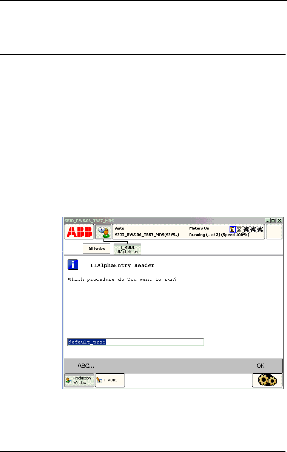
2 Functions
2.142. UIAlphaEntry - User Alpha Entry
RobotWare-OS
3HAC 16581-1 Revision: J1032
© Copyright 2004-2010 ABB. All rights reserved.
2.142. UIAlphaEntry - User Alpha Entry
Usage
UIAlphaEntry (User Interaction Alpha Entry) is used to let the operator enter a string from
the available user device, such as the FlexPendant. A message is written to the operator, who
answers with a text string. The string is then transferred back to the program.
Basic examples
Basic examples of the instruction
UIAlpaEntry are illustrated below.
See More examples on page 1035.
Example 1
VAR string answer;
...
answer := UIAlphaEntry(
\Header:= "UIAlphaEntry Header",
\Message:= "Which procedure do You want to run?"
\Icon:=iconInfo
\InitString:= "default_proc");
%answer%;
xx0500002437
Above alpha message box with icon, header, message, and init string are written on the
FlexPendant display. The user edit init string or write a new string with the supported Alpha
Pad. Program execution waits until OK is pressed and then the written string is returned in
the variable
answer. The program then calls the specified procedure with late binding.
Continues on next page

2 Functions
2.142. UIAlphaEntry - User Alpha Entry
RobotWare-OS
10333HAC 16581-1 Revision: J
© Copyright 2004-2010 ABB. All rights reserved.
Return value
Data type:
string
This functions returns the input string.
If function breaks via \
BreakFlag:
- If parameter \InitString is specified, this string is returned
- If parameter \
InitString is not specified, empty string "" is returned.
If function breaks via
ERROR handler, no return value will be returned at all.
Arguments
UIAlphaEntry ([\Header][\Message]|[\MsgArray]
[\Wrap][\Icon][\InitString]
[\MaxTime][\DIBreak][\DOBreak][\BreakFlag])
[\Header]
Data type: string
Header text to be written at the top of the message box. Max. 40 characters.
[\Message]
Data type: string
One text line to be written on the display. Max 55 characters.
[\MsgArray]
Message Array
Data type:
string
Several text lines from an array to be written on the display.
Only one of parameter \
Message or \MsgArray can be used at the same time.
Max. layout space is 9 lines with 55 characters.
[\Wrap]
Data type: switch
If selected, all the specified strings in the argument \
MsgArray will be concatenated to one
string with single space between each individual strings and spread out on as few lines as
possible.
Default, each string in the argument \
MsgArray will be on separate line on the display.
[\Icon]
Data type: icondata
Defines the icon to be displayed. Only one of the predefined icons of type icondata can be
used. See Predefined data on page 1034.
Default no icon.
[\InitString]
Data type: string
An initial string to be display in the text entry box as default.
Continued
Continues on next page

2 Functions
2.142. UIAlphaEntry - User Alpha Entry
RobotWare-OS
3HAC 16581-1 Revision: J1034
© Copyright 2004-2010 ABB. All rights reserved.
[\MaxTime]
Data type: num
The maximum amount of time in seconds that program execution waits. If the OK button is
not pressed within this time, the program continues to execute in the error handler unless the
BreakFlag is used (see below). The constant ERR_TP_MAXTIME can be used to test whether
or not the maximum time has elapsed.
[\DIBreak]
Digital Input Break
Data type:
signaldi
The digital input signal that may interrupt the operator dialog. If the OK button is not pressed
before the signal is set to 1 (or is already 1), the program continues to execute in the error
handler, unless the
BreakFlag is used (see below). The constant ERR_TP_DIBREAK can be
used to test whether or not this has occurred.
[\DOBreak]
Digital Output Break
Data type:
signaldo
The digital output signal that may interrupt the operator dialog. If the OK button is not pressed
before the signal is set to 1 (or is already 1), the program continues to execute in the error
handler, unless the
BreakFlag is used (see below). The constant ERR_TP_DOBREAK can be
used to test whether or not this has occurred.
[\BreakFlag]
Data type: errnum
A variable (before used set to 0 by the system) that will hold the error code if \MaxTime,
\DIBreak or \DOBreak is used. The constants ERR_TP_MAXTIME, ERR_TP_DIBREAK and
ERR_TP_DOBREAK can be used to select the reason. If this optional variable is omitted, the
error handler will be executed.
Program execution
The alpha message box with alpha pad, icon, header, message lines, and init string are
displayed according to the programmed arguments. Program execution waits until the user
edits or creates a new string and presses OK, or the message box is interrupted by time-out or
signal action. The input string and interrupt reason are transferred back to the program.
New message box on TRAP level takes focus from message box on basic level.
Predefined data
!Icons:
CONST icondata iconNone := 0;
CONST icondata iconInfo := 1;
CONST icondata iconWarning := 2;
CONST icondata iconError := 3;
Continued
Continues on next page

2 Functions
2.142. UIAlphaEntry - User Alpha Entry
RobotWare-OS
10353HAC 16581-1 Revision: J
© Copyright 2004-2010 ABB. All rights reserved.
More examples
More examples of the function
UIAlphaEntry are illustrated below.
Example 1
VAR errnum err_var;
VAR string answer;
VAR string logfile;
...
answer := UIAlphaEntry (\Header:= "Log file name:"
\Message:= "Enter the name of the log file to create?"
\Icon:=iconInfo
\InitString:= "signal.log" \MaxTime:=60
\DIBreak:=di5\BreakFlag:=err_var);
TEST err_var
CASE ERR_TP_MAXTIME:
CASE ERR_TP_DIBREAK:
! No operator answer
logfile:="signal.log";
CASE 0:
! Operator answer
logfile := answer;
DEFAULT:
! Not such case defined
ENDTEST
The message box is displayed and the operator can enter a string and press OK. The message
box can also be interrupted with time out or break by digital input signal. In the program it’s
possible to find out the reason and take the appropriate action.
Error handling
If parameter \
BreakFlag is not used, these situations can then be dealt with by the error
handler:
If there is a time-out (parameter
\MaxTime) before an input from the operator, the system
variable
ERRNO is set to ERR_TP_MAXTIME and the execution continues in the error handler.
If digital input is set (parameter \
DIBreak) before an input from the operator, the system
variable
ERRNO is set to ERR_TP_DIBREAK and the execution continues in the error handler.
If a digital output is set (parameter \
DOBreak) before an input from the operator, the system
variable
ERRNO is set to ERR_TP_DOBREAK and the execution continues in the error handler.
This situation can only be dealt with by the error handler:
If there is no client, e.g. a FlexPendant, to take care of the instruction, the system variable
ERRNO is set to ERR_TP_NO_CLIENT and the execution continues in the error handler.
Limitations
Avoid using too small a value for the time-out parameter \
MaxTime when UIAlphaEntry is
frequently executed, for example in a loop. It can result in an unpredictable behavior of the
system performance, like slow response of the FlexPendant.
Continued
Continues on next page

2 Functions
2.142. UIAlphaEntry - User Alpha Entry
RobotWare-OS
3HAC 16581-1 Revision: J1036
© Copyright 2004-2010 ABB. All rights reserved.
Syntax
UIAlphaEntry´(´
[´\´Header’:=’ <expression (IN) of string>]
[´\´ Message’:=’ <expression (IN) of string>]
| [´\´MsgArray’:=’<array {*} (IN) of string>]
[´\´Wrap]
[´\´Icon’:=’ <expression (IN) of icondata>]
[´\´InitString’:=’<expression (IN) of string>]
[´\´MaxTime’:=’ <expression (IN) of num>]
[´\´DIBreak’:=’ <variable (VAR) of signaldi>]
[´\´DOBreak´:=´<variable (VAR) of signaldo>]
[’\’BreakFlag ´:=´ <var or pers (INOUT) of errnum>]‘)’
A function with return value of the data type string.
Related information
For information about See
Icon display data icondata - Icon display data on page 1121
User Interaction Message Box type basic UIMsgBox - User Message Dialog Box type
basic on page 644
User Interaction Message Box type
advanced
UIMessageBox - User Message Box type
advanced on page 1057
User Interaction Number Entry UINumEntry - User Number Entry on page
1064
User Interaction Number Tune UINumTune - User Number Tune on page
1070
User Interaction List View UIListView - User List View on page 1050
System connected to FlexPendant etc. UIClientExist - Exist User Client on page 1037
Procedure call with Late binding Technical reference manual - RAPID
overview, section Basic characteristics -
Routines - Procedure call
Clean up the Operator window TPErase - Erases text printed on the
FlexPendant on page 556
Continued

2 Functions
2.143. UIClientExist - Exist User Client
RobotWare - OS
10373HAC 16581-1 Revision: J
© Copyright 2004-2010 ABB. All rights reserved.
2.143. UIClientExist - Exist User Client
Usage
UIClientExist (User Interaction Client Exist) is used to check if some User Device such
as the FlexPendant is connected to the controller.
Basic examples
Basic examples of the function
UIClientExist are illustrated below.
Example 1
IF UIClientExist() THEN
! Possible to get answer from the operator
! The TPReadFK and UIMsgBox ... can be used
ELSE
! Not possible to communicate with any operator
ENDIF
The test is done if it is possible to get some answer from the operator of the system.
Return value
Data type:
bool
Returns TRUE if a FlexPendant is connected to the system, otherwise FALSE.
Limitations
UIClientExist returns TRUE up to 16 seconds. After that, the FlexPendant is removed.
After that time,
UIClientExist returns FALSE (i.e when network connection lost from
FlexPendent is detected). Same limitation when the FlexPendant is connected again.
Syntax
UIClientExist’(’ ’)
A function with return value of the type bool.
Related information
For information about See
User Interaction Message Box type basic UIMsgBox - User Message Dialog Box type
basic on page 644
User Interaction Message Box type advanced UIMessageBox - User Message Box type
advanced on page 1057
User Interaction Number Entry UINumEntry - User Number Entry on page
1064
User Interaction Number Tune UINumTune - User Number Tune on page
1070
User Interaction Alpha Entry UIAlphaEntry - User Alpha Entry on page
1032
User Interaction List View UIListView - User List View on page 1050
Clean up the Operator window TPErase - Erases text printed on the
FlexPendant on page 556
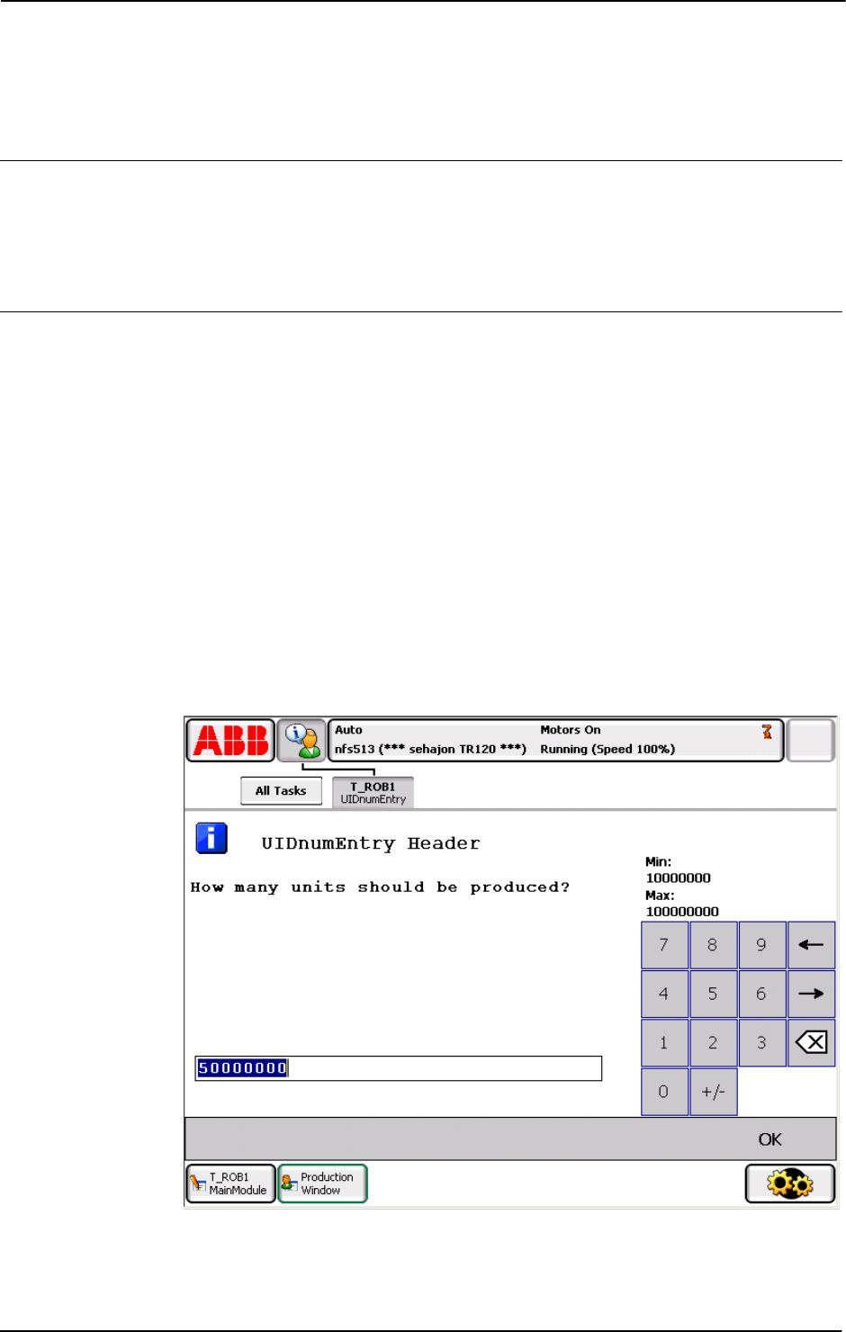
2 Functions
2.144. UIDnumEntry - User Number Entry
RobotWare - OS
3HAC 16581-1 Revision: J1038
© Copyright 2004-2010 ABB. All rights reserved.
2.144. UIDnumEntry - User Number Entry
Usage
UIDnumEntry (User Interaction Number Entry) is used to let the operator enter a numeric
value from the available user device, such as the FlexPendant. A message is written to the
operator, who answers with a numeric value. The numeric value is then checked, approved
and transferred back to the program.
Basic examples
Basic examples of the function
UIDnumEntry are illustrated below.
See also More examples on page 1041.
Example 1
VAR dnum answer;
...
answer := UIDnumEntry(
\Header:="UIDnumEntry Header"
\Message:="How many units should be produced?"
\Icon:=iconInfo
\InitValue:=50000000
\MinValue:=10000000
\MaxValue:=100000000
\AsInteger);
xx0900001064
Continues on next page

2 Functions
2.144. UIDnumEntry - User Number Entry
RobotWare - OS
10393HAC 16581-1 Revision: J
© Copyright 2004-2010 ABB. All rights reserved.
Above, the numeric message box with icon, header, message, init-, max-, and minvalue
written on the FlexPendant display. The message box checks that the operator selects an
integer within the value range. Program execution waits until OK is pressed and then the
selected numerical value is returned.
Return value
Data type:
dnum
This function returns the input numeric value.
If function breaks via
\BreakFlag:
• If parameter \InitValue is specified, this value is returned
• If parameter \InitValue is not specified, value 0 is returned.
If function breaks via
ERROR handler there is no return value at all.
Arguments
UIDnumEntry ( [\Header] [\Message] | [\MsgArray]
[\Wrap] [\Icon] [\InitValue] [\MinValue] [\MaxValue]
[\AsInteger] [\MaxTime] [\DIBreak] [\DOBreak]
\BreakFlag] )
[\Header]
Data type: string
Header text to be written at the top of the message box. Max. 40 characters.
[\Message]
Data type: string
One text line to be written on the display. Max. 40 characters.
[\MsgArray]
Message Array
Data type:
string
Several text lines from an array to be written on the display.
Only one of parameter
\Message or \MsgArray can be used at the same time.
Max. layout space is 9 lines with 40 characters each.
[\Wrap]
Data type: switch
If selected, all the specified strings in the argument \MsgArray will be concatenated to one
string with a single space between each individual string, and spread out on as few lines as
possible.
Default, each string in the argument
\MsgArray will be on a separate line on the display.
[\Icon]
Data type: icondata
Defines the icon to be displayed. Only one of the predefined icons of type icondata can be
used. See Predefined data on page 1041.
Default no icon.
Continued
Continues on next page

2 Functions
2.144. UIDnumEntry - User Number Entry
RobotWare - OS
3HAC 16581-1 Revision: J1040
© Copyright 2004-2010 ABB. All rights reserved.
[\InitValue]
Data type: dnum
Initial value that is displayed in the entry box.
[\MinValue]
Data type: dnum
The minimum value for the return value.
[\MaxValue]
Data type: dnum
The maximum value for the return value.
[\AsInteger]
Data type: switch
Eliminates the decimal point from the number pad to ensure that the return value is an integer.
[\MaxTime]
Data type: num
The maximum amount of time in seconds that program execution waits. If the OK button is
not pressed within this time, the program continues to execute in the error handler unless the
BreakFlag is used (see below). The constant ERR_TP_MAXTIME can be used to test whether
or not the maximum time has elapsed.
[\DIBreak]
Digital Input Break
Data type:
signaldi
The digital input signal that may interrupt the operator dialog. If the OK button is not pressed
before the signal is set to 1 (or is already 1) then the program continues to execute in the error
handler unless the
BreakFlag is used (see below). The constant ERR_TP_DIBREAK can be
used to test whether or not this has occurred.
[\DOBreak]
Digital Output Break
Data type:
signaldo
The digital output signal that may interrupt the operator dialog. If the OK button is not pressed
before the signal is set to 1 (or is already 1) then the program continues to execute in the error
handler unless the
BreakFlag is used (see below). The constant ERR_TP_DOBREAK can be
used to test whether or not this has occurred.
[\BreakFlag]
Data type: errnum
A variable (before used, set to 0 by the system) that will hold the error code if \MaxTime,
\DIBreak, or \DOBreak is used. The constants ERR_TP_MAXTIME, ERR_TP_DIBREAK, and
ERR_TP_DOBREAK can be used to select the reason. If this optional variable is omitted, the
error handler will be executed.
Continued
Continues on next page

2 Functions
2.144. UIDnumEntry - User Number Entry
RobotWare - OS
10413HAC 16581-1 Revision: J
© Copyright 2004-2010 ABB. All rights reserved.
Program execution
The numeric message box with numeric pad, icon, header, message lines, init-, max-, and
minvalue is displayed according to the programmed arguments. Program execution waits
until the user has entered an approved numeric value and pressed OK or the message box is
interrupted by timeout or signal action. The input numeric value and interrupt reason are
transferred back to the program.
New message box on TRAP level takes focus from message box on basic level.
Predefined data
!Icons:
CONST icondata iconNone := 0;
CONST icondata iconInfo := 1;
CONST icondata iconWarning := 2;
CONST icondata iconError := 3;
More examples
More examples of the function
UIDnumEntry are illustrated below.
Example 1
VAR errnum err_var;
VAR dnum answer;
VAR dnum distance;
...
answer := UIDnumEntry (\Header:= "BWD move on path"
\Message:="Enter the path overlap?" \Icon:=iconInfo
\InitValue:=5 \MinValue:=0 \MaxValue:=10
\MaxTime:=60 \DIBreak:=di5 \BreakFlag:=err_var);
TEST err_var
CASE ERR_TP_MAXTIME:
CASE ERR_TP_DIBREAK:
! No operator answer distance := 5;
CASE 0
! Operator answer
distance := answer;
DEFAULT:
! No such case defined
ENDTEST
The message box is displayed and the operator can enter a numeric value and press OK. The
message box can also be interrupted with a time out or break by digital input signal. In the
program, it is possible to find out the reason and take the appropriate action.
Continued
Continues on next page

2 Functions
2.144. UIDnumEntry - User Number Entry
RobotWare - OS
3HAC 16581-1 Revision: J1042
© Copyright 2004-2010 ABB. All rights reserved.
Error handling
If parameter
\BreakFlag is not used, these situations can then be dealt with by the error
handler:
• If there is a timeout (parameter \MaxTime) before an input from the operator then the
system variable
ERRNO is set to ERR_TP_MAXTIME and the execution continues in the
error handler.
• If a digital input is set (parameter \DIBreak) before an input from the operator then
the system variable
ERRNO is set to ERR_TP_DIBREAK and the execution continues in
the error handler.
• If a digital output is set (parameter \DOBreak) before an input from the operator then
the system variable
ERRNO is set to ERR_TP_DOBREAK and the execution continues in
the error handler.
Limitations
Avoid using too small a value for the timeout parameter
\MaxTime when UIDnumEntry is
frequently executed, for example, in a loop. It can result in unpredictable behavior from the
system performance, like the slow response of the FlexPendant.
Syntax
UIDnumEntry´(´
[´\´Header´:=´ <expression (IN) of string>]
[Message’:=’ <expression (IN) of string> ]
| [´\´MsgArray’:=’<array {*} (IN) of string>]
[´\´Wrap]
[´\´Icon’:=’ <expression (IN) of icondata>]
[´\´InitValue’:=’<expression (IN) of dnum>]
[´\´MinValue’:=’<expression (IN) of dnum>]
[´\´MaxValue’:=’<expression (IN) of dnum>]
[´\´AsInteger]
[´\´MaxTime’:=’ <expression (IN) of num>]
[\´DIBreak’:=’ <variable (VAR) of signaldi>]
[´\´DOBreak’:=’ <variable (VAR) of signaldo>]
[´\´BreakFlag’:=’ <var or pers (INOUT) of errnum>] ´)´
A function with return value of the data type dnum.
Continued
Continues on next page

2 Functions
2.144. UIDnumEntry - User Number Entry
RobotWare - OS
10433HAC 16581-1 Revision: J
© Copyright 2004-2010 ABB. All rights reserved.
Related information
For information about See
Icon display data icondata - Icon display data on page 1121
User Interaction Message Box type basic UIMsgBox - User Message Dialog Box type
basic on page 644
User Interaction Message Box type advanced UIMessageBox - User Message Box type
advanced on page 1057
User Interaction Number Entry UINumEntry - User Number Entry on page
1064
User Interaction Number Tune UIDnumTune - User Number Tune on page
1044
User Interaction Number Tune UINumTune - User Number Tune on page
1070
User Interaction Alpha Entry UIAlphaEntry - User Alpha Entry on page
1032
User Interaction List View UIListView - User List View on page 1050
System connected to FlexPendant etc. UIClientExist - Exist User Client on page
1037
Clean up the Operator window TPErase - Erases text printed on the
FlexPendant on page 556
Continued
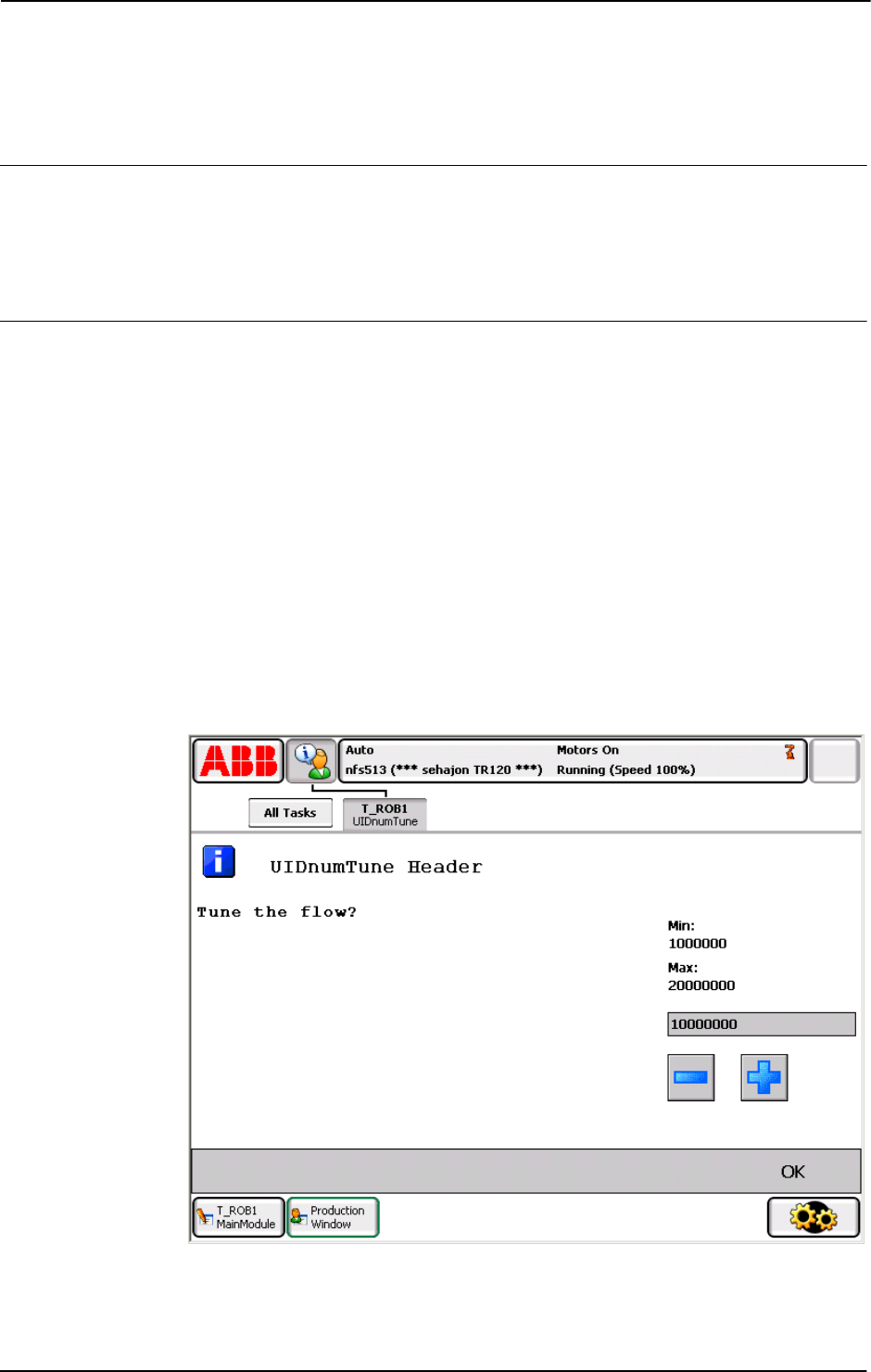
2 Functions
2.145. UIDnumTune - User Number Tune
RobotWare - OS
3HAC 16581-1 Revision: J1044
© Copyright 2004-2010 ABB. All rights reserved.
2.145. UIDnumTune - User Number Tune
Usage
UIDnumTune (User Interaction Number Tune) is used to let the operator tune a numeric value
from the available user device, such as the FlexPendant. A message is written to the operator,
who tunes a numeric value. The tuned numeric value is then checked, approved and
transferred back to the program.
Basic examples
Basic examples of the function
UIDnumTune are illustrated below.
See also More examples on page 1047.
Example 1
VAR dnum flow;
...
flow := UIDnumTune(
\Header:="UIDnumTune Header"
\Message:="Tune the flow?"
\Icon:=iconInfo,
10000000,
1000000
\MinValue:=1000000
\MaxValue:=20000000);
xx0900001063
Continues on next page

2 Functions
2.145. UIDnumTune - User Number Tune
RobotWare - OS
10453HAC 16581-1 Revision: J
© Copyright 2004-2010 ABB. All rights reserved.
Above, the numeric tune message box with icon, header, message, init-, increment, max-, and
minvalue written on the FlexPendant display. The message box checks that the operator tunes
the
flow value with step 1000000 from init value 10000000 and is within the value range
1000000-20000000. Program execution waits until OK is pressed and then the selected
numerical value is returned and stored in the variable
flow.
Return value
Data type:
dnum
This function returns the tuned numeric value.
If function breaks via
\BreakFlag, the specified InitValue is returned.
If function breaks via
ERROR handler, no return value is returned at all.
Arguments
UIDnumTune ( [\Header] [\Message] | [\MsgArray] [\Wrap]
[\Icon] InitValue Increment [\MinValue] [\MaxValue]
[\MaxTime] [\DIBreak] [\DOBreak] [\BreakFlag] )
[\Header]
Data type: string
Header text to be written at the top of the message box. Max. 40 characters.
[\Message]
Data type: string
One text line to be written on the display. Max. 40 characters.
[\MsgArray]
Message Array
Data type:
string
Several text lines from an array to be written on the display.
Only one of parameter
\Message or \MsgArray can be used at the same time.
Max. layout space is 11 lines with 40 characters each.
[\Wrap]
Data type: switch
If selected, all the specified strings in the argument \MsgArray will be concatenated to one
string with a single space between each individual string and spread out on as few lines as
possible.
Default, each string in the argument
\MsgArray will be on a separate line on the display.
[\Icon]
Data type: icondata
Defines the icon to be displayed. Only one of the predefined icons of type icondata can be
used. See Predefined data on page 1047.
Default no icon.
Continued
Continues on next page

2 Functions
2.145. UIDnumTune - User Number Tune
RobotWare - OS
3HAC 16581-1 Revision: J1046
© Copyright 2004-2010 ABB. All rights reserved.
InitValue
Initial Value
Data type:
dnum
Initial value that is displayed in the entry box.
Increment
Data type: dnum
This parameter specifies how much the value should change when the plus or minus button
is pressed.
[\MinValue]
Data type: dnum
The minimum value for the return value.
[\MaxValue]
Data type: dnum
The maximum value for the return value.
[\MaxTime]
Data type: num
The maximum amount of time in seconds that program execution waits. If the OK button is
not pressed within this time, the program continues to execute in the error handler unless the
BreakFlag is used (see below). The constant ERR_TP_MAXTIME can be used to test whether
or not the maximum time has elapsed.
[\DIBreak]
Digital Input Break
Data type:
signaldi
The digital input signal that may interrupt the operator dialog. If the OK button is not pressed
before the signal is set to 1 (or is already 1) then the program continues to execute in the error
handler unless the
BreakFlag is used (see below). The constant ERR_TP_DIBREAK can
be used to test whether or not this has occurred.
[\DOBreak]
Digital Output Break
Data type:
signaldo
The digital output signal that may interrupt the operator dialog. If the OK button is not pressed
before the signal is set to 1 (or is already 1) then the program continues to execute in the error
handler unless the
BreakFlag is used (see below). The constant ERR_TP_DOBREAK can be
used to test whether or not this has occurred.
[\BreakFlag]
Data type: errnum
A variable (before used, set to 0 by the system) that will hold the error code if \MaxTime,
\DIBreak, or \DOBreak is used. The constants ERR_TP_MAXTIME, ERR_TP_DIBREAK, and
ERR_TP_DOBREAK can be used to select the reason. If this optional variable is omitted, the
error handler will be executed.
Continued
Continues on next page

2 Functions
2.145. UIDnumTune - User Number Tune
RobotWare - OS
10473HAC 16581-1 Revision: J
© Copyright 2004-2010 ABB. All rights reserved.
Program execution
The numeric tune message box with tune +/- buttons, icon, header, message lines, init-,
increment, max, and minvalue is displayed according to the programmed arguments. Program
execution waits until the user has tuned the numeric value and pressed OK or the message
box is interrupted by timeout or signal action. The input numeric value and interrupt reason
are transferred back to the program.
New message box on
TRAP level takes focus from message box on basic level.
Predefined data
!Icons:
CONST icondata iconNone := 0;
CONST icondata iconInfo := 1;
CONST icondata iconWarning := 2;
CONST icondata iconError := 3;
More examples
More examples of the function
UIDnumTune are illustrated below.
Example 1
VAR errnum err_var;
VAR dnum tune_answer;
VAR dnum distance;
...
tune_answer := UIDnumTune (\Header:=" BWD move on path"
\Message:="Enter the path overlap?" \Icon:=iconInfo,
5, 1 \MinValue:=0 \MaxValue:=10
\MaxTime:=60 \DIBreak:=di5 \BreakFlag:=err_var);
TEST err_var
CASE ERR_TP_MAXTIME:
CASE ERR_TP_DIBREAK:
! No operator answer
distance := 5;
CASE 0:
! Operator answer
distance := tune_answer;
DEFAULT:
! No such case defined
ENDTEST
The tune message box is displayed and the operator can tune the numeric value and press OK.
The message box can also be interrupted with timeout or break by digital input signal. In the
program, it is possible to find out the reason and take the appropriate action.
Continued
Continues on next page

2 Functions
2.145. UIDnumTune - User Number Tune
RobotWare - OS
3HAC 16581-1 Revision: J1048
© Copyright 2004-2010 ABB. All rights reserved.
Error handling
If parameter
\BreakFlag is not used then these situations can be dealt with by the error
handler:
• If there is a timeout (parameter \MaxTime) before an input from the operator, the
system variable
ERRNO is set to ERR_TP_MAXTIME and the execution continues in the
error handler.
• If a digital input is set (parameter \DIBreak) before an input from the operator, the
system variable
ERRNO is set to ERR_TP_DIBREAK and the execution continues in the
error handler.
• If a digital output is set (parameter \DOBreak) before an input from the operator, the
system variable
ERRNO is set to ERR_TP_DOBREAK and the execution continues in the
error handler.
This situation can only be dealt with by the error handler:
• If there is no client, e.g. a FlexPendant, to take care of the instruction then the system
variable
ERRNO is set to ERR_TP_NO_CLIENT and the execution continues in the error
handler.
• If the initial value (parameter \InitValue) is not specified within the range of the
minimum and maximum value (parameters
\MinValue and \MaxValue) then the
system variable
ERRNO is set to ERR_UI_INITVALUE and the execution continues in
the error handler.
• If the minimum value (parameter \MinValue) is greater than the maximum value
(parameter
\MaxValue) then the system variable ERRNO is set to ERR_UI_MAXMIN
and the execution continues in the error handler.
Limitations
Avoid using too small a value for the timeout parameter
\MaxTime when UIDnumTune is
frequently executed, for example, in a loop. It can result in unpredictable behavior from the
system performance, like a slow response of the FlexPendant.
Syntax
UIDnumTune’(’
[’\’Header’:=’ <expression (IN) of string>]
[’\’Message’:=’ <expression (IN) of string> ]
| [‘\’MsgArray’:=’<array {*} (IN) of string>]
[’\’Wrap]
[’\’Icon’:=’ <expression (IN) of icondata>] ’,’]
[InitValue’:=’ ] <expression (IN) of dnum> ’,’
[Increment’:=’ ] <expression (IN) of dnum>
[’\’MinValue’:=’ <expression (IN) of dnum>]
[’\’MaxValue’:=’ <expression(IN) of dnum>]
[’\’MaxTime’:=’ <expression (IN) of num>]
[’\’DIBreak’:=’ <variable (VAR) of signaldi>]
[’\’DOBreak’:=’ <variable (VAR) of signaldo>]
[’\’BreakFlag’:=’ <var or pers (INOUT) of errnum>] ’)’
A function with return value of the data type dnum.
Continued
Continues on next page

2 Functions
2.145. UIDnumTune - User Number Tune
RobotWare - OS
10493HAC 16581-1 Revision: J
© Copyright 2004-2010 ABB. All rights reserved.
Related information
For information about See
Icon display data icondata - Icon display data on page 1121
User Interaction Message Box type basic UIMsgBox - User Message Dialog Box type
basic on page 644
User Interaction Message Box type advanced UIMessageBox - User Message Box type
advanced on page 1057
User Interaction Number Entry UIDnumEntry - User Number Entry on page
1038
User Interaction Number Entry UINumEntry - User Number Entry on page
1064
User Interaction Number Tune UINumTune - User Number Tune on page
1070
User Interaction Alpha Entry UIAlphaEntry - User Alpha Entry on page
1032
User Interaction List View UIListView - User List View on page 1050
System connected to FlexPendant etc. UIClientExist - Exist User Client on page
1037
Clean up the Operator window TPErase - Erases text printed on the
FlexPendant on page 556
Continued

2 Functions
2.146. UIListView - User List View
RobotWare - OS
3HAC 16581-1 Revision: J1050
© Copyright 2004-2010 ABB. All rights reserved.
2.146. UIListView - User List View
Usage
UIListView (User Interaction List View) is used to define menu lists with text and optional
icons on the available User Device such as the FlexPendant. The menu has two different
styles, one with validations buttons and one that reacts instantly to the user selection.
Basic examples
Basic examples of the function
UIListView are illustrated below.
See also More examples on page 1054.
Example 1
CONST listitem list{3} := [ ["","Item 1"], ["","Item 2"],
["","Item 3"] ];
VAR num list_item;
VAR btnres button_answer;
...
list_item := UIListView (
\Result:=button_answer
\Header:="UIListView Header",
list
\Buttons:=btnOKCancel
\Icon:=iconInfo
\DefaultIndex:=1);
IF button_answer = resOK THEN
IF list_item = 1 THEN
! Do item1
ELSEIF list_item = 2 THEN
! Do item 2
ELSE
! Do item3
ENDIF
ELSE
! User has select Cancel
ENDIF
Continues on next page
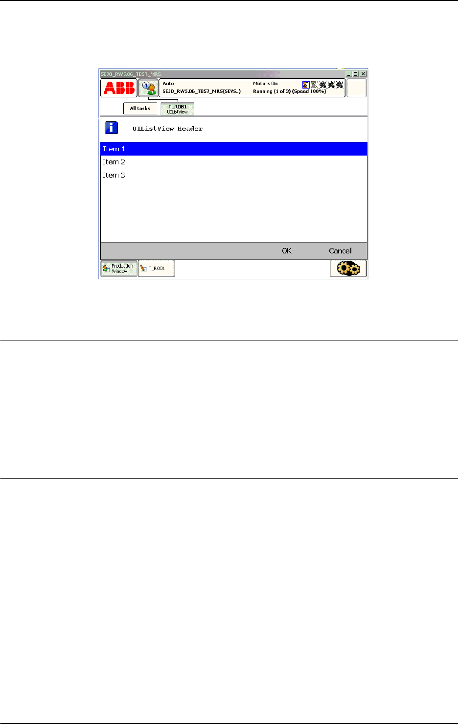
2 Functions
2.146. UIListView - User List View
RobotWare - OS
10513HAC 16581-1 Revision: J
© Copyright 2004-2010 ABB. All rights reserved.
xx0500002416
Above menu list with icon, header, menu Item 1 ... Item 3, and buttons are written on
the FlexPendant display. Program execution waits until OK or Cancel is pressed. Both the
selection in the list and the pressed button are transfered to the program.
Return value
Data type:
num
This function returns the user selection in the list menu corresponding to the index in the array
specified in the parameter
ListItems.
If the function breaks via
\BreakFlag:
• If parameter \DefaultIndex is specified, this index is returned
• If parameter \DefaultIndex is not specified, 0 is returned
If function breaks via
ERROR handler, no return value is returned at all.
Arguments
UIListView ( [\Result] [\Header] ListItems [\Buttons] |
[\BtnArray] [\Icon] [\DefaultIndex ] [\MaxTime]
[\DIBreak] [\DOBreak] [\BreakFlag])
[\Result]
Data type: btnres
The numeric value of the button that is selected from the list menu box.
If argument
\Buttons is used, the predefined symbolic constants of type btnres is returned.
If argument
\BtnArray is used, the corresponding array index is returned.
Argument
\Result set to resUnkwn equal to 0 if one of following condition:
• none of parameters \Buttons or \BtnArray are used
• argument \Buttons:=btnNone is used
• if the function breaks via \BreakFlag or ERROR handler
See Predefined data on page 1054.
Continued
Continues on next page

2 Functions
2.146. UIListView - User List View
RobotWare - OS
3HAC 16581-1 Revision: J1052
© Copyright 2004-2010 ABB. All rights reserved.
[\Header]
Data type: string
Header text to be written at the top of the list menu box. Max. 40 characters.
ListItem
Data type: listitem
An array with one or several list menu items to be displayed consisting of:
Component
image of type string:
The name of the icon image that should be used. To launch own images, the images has to be
placed in the
HOME: directory in the active system or directly in the active system.
The recommendation is to place the files in the
HOME: directory so that they are saved if a
Backup and Restore is done.
A warmstart is required and then the FlexPendant loads the images.
A demand on the system is that the RobotWare option FlexPendant Interface is used.
The image that will be shown can have the width and height of 28 pixels. If the image is
bigger, then it will be resized to show only 28 * 28 pixels.
No exact value can be specified on the size that an image can have or the amount of images
that can be loaded to the FlexPendant. It depends on the size of other files loaded to the
FlexPendant. The program execution will just continue if an image is used that has not been
loaded to the FlexPendant.
Use empty string ”” or stEmpty if no icon to display.
Component
text of type string:
• The text for the menu line to display.
• Max. 75 characters for each list menu item.
[\Buttons]
Data type: buttondata
Defines the push buttons to be displayed. Only one of the predefined buttons combination of
type buttondata can be used. See Predefined data on page 1054.
[\BtnArray]
Button Array
Data type:
string
Own definition of push buttons stored in an array of strings. This function returns the array
index when corresponding string is selected.
Only one of parameter
\Buttons or \BtnArray can be used at the same time. If none of
the parameters
\Buttons or \BtnArray or argument \Buttons:=btnNone are used then
the menu list reacts instantly to the user selection.
Max. 5 buttons with 42 characters each.
Continued
Continues on next page

2 Functions
2.146. UIListView - User List View
RobotWare - OS
10533HAC 16581-1 Revision: J
© Copyright 2004-2010 ABB. All rights reserved.
[\Icon]
Data type: icondata
Defines the icon to be displayed. Only one of the predefined icons of type icondata can be
used.
Default no icon. See Predefined data on page 1054.
[\DefaultIndex]
Data type: num
The default user selection in the list menu corresponding to the index in the array specified in
the parameter
ListItems.
[\MaxTime]
Data type: num
The maximum amount of time in seconds that program execution waits. If no button is
pressed or no selection is done within this time then the program continues to execute in the
error handler unless the
BreakFlag is used (see below). The constant ERR_TP_MAXTIME can
be used to test whether or not the maximum time has elapsed.
[\DIBreak]
Digital Input Break
Data type:
signaldi
The digital input signal that may interrupt the operator dialog. If no button is pressed or no
selection is done before the signal is set to 1 (or is already 1) then the program continues to
execute in the error handler, unless the
BreakFlag is used (see below). The constant
ERR_TP_DIBREAK can be used to test whether or not this has occurred.
[\DOBreak]()
Digital Output Break
Data type:
signaldo
The digital output signal that may interrupt the operator dialog. If no button is pressed or no
selection is done before the signal is set to 1 (or is already 1) then the program continues to
execute in the error handler, unless the
BreakFlag is used (see below). The constant
ERR_TP_DOBREAK can be used to test whether or not this has occurred.
[\BreakFlag]
Data type: errnum
A variable that will hold the error code if \MaxTime, \DIBreak, or \DOBreak is used. The
constants
ERR_TP_MAXTIME, ERR_TP_DIBREAK, and ERR_TP_DOBREAK can be used to
select the reason. If this optional variable is omitted, the error handler will be executed.
Program execution
The menu list with icon, header, list items, and default item are displayed according to the
programmed arguments. Program execution waits until the operator has done the selection or
the menu list is interrupted by time-out or signal action. The selected list item and interrupt
reason are transferred back to the program.
New menu list on TRAP level takes focus from menu list on basic level.
Continued
Continues on next page

2 Functions
2.146. UIListView - User List View
RobotWare - OS
3HAC 16581-1 Revision: J1054
© Copyright 2004-2010 ABB. All rights reserved.
Predefined data
!Icons:
CONST icondata iconNone := 0;
CONST icondata iconInfo := 1;
CONST icondata iconWarning := 2;
CONST icondata iconError := 3;
!Buttons:
CONST buttondata btnNone := -1;
CONST buttondata btnOK := 0;
CONST buttondata btnAbrtRtryIgn := 1;
CONST buttondata btnOKCancel := 2;
CONST buttondata btnRetryCancel := 3;
CONST buttondata btnYesNo := 4;
CONST buttondata btnYesNoCancel := 5;
!Results:
CONST btnres resUnkwn := 0;
CONST btnres resOK := 1;
CONST btnres resAbort := 2;
CONST btnres resRetry := 3;
CONST btnres resIgnore := 4;
CONST btnres resCancel := 5;
CONST btnres resYes := 6;
CONST btnres resNo := 7;
More examples
More examples of the function
UIListView are illustrated below.
Example 1
CONST listitem list{2} := [ ["","Calibrate tool1"], ["","Calibrate
tool2"] ];
VAR num list_item;
VAR errnum err_var;
...
list_item := UIListView
( \Header:="Select tool ?",
list \Icon:=iconInfo
\MaxTime:=60
\DIBreak:=di5
\BreakFlag:=err_var);
TEST err_var
CASE ERR_TP_MAXTIME:
CASE ERR_TP_DIBREAK:
! No operator answer
CASE 0:
Continued
Continues on next page

2 Functions
2.146. UIListView - User List View
RobotWare - OS
10553HAC 16581-1 Revision: J
© Copyright 2004-2010 ABB. All rights reserved.
! Operator answer
IF list_item =1 THEN
! Calibrate tool1
ELSEIF list_item=2 THEN
! Calibrate tool2
ENDIF
DEFAULT:
! Not such case defined
ENDTEST
The message box is displayed and the operator can select an item in the list. The message box
can also be interrupted with time out or break by digital input signal. In the program it’s
possible to find out the reason and take the appropriate action.
Error handling
If parameter
\BreakFlag is not used, these situations can then be dealt with by the error
handler:
• If there is a time-out (parameter \MaxTime) before an input from the operator, the
system variable
ERRNO is set to ERR_TP_MAXTIME and the execution continues in the
error handler.
• If digital input is set (parameter \DIBreak) before an input from the operator, the
system variable
ERRNO is set to ERR_TP_DIBREAK and the execution continues in the
error handler.
• If a digital output is set (parameter \DOBreak) before an input from the operator, the
system variable
ERRNO is set to ERR_TP_DOBREAK and the execution continues in the
error handler.
This situation can only be dealt with by the error handler:
• If there is no client, e.g. a FlexPendant, to take care of the instruction then the system
variable
ERRNO is set to ERR_TP_NO_CLIENT and the execution continues in the error
handler.
Limitations
Avoid using too small a value for the time-out parameter
\MaxTime when UIListView is
frequently executed, for example in a loop. It can result in unpredictable behavior from the
system performance, like slow response of the FlexPendant.
Continued
Continues on next page

2 Functions
2.146. UIListView - User List View
RobotWare - OS
3HAC 16581-1 Revision: J1056
© Copyright 2004-2010 ABB. All rights reserved.
Syntax
UIListView ’(’
[[’\’Result ´:=´ <var or pers (INOUT) of btnres>]
[’\’Header ´:=´ <expression (IN) of string>] ’,’]
[ListItems ´=´] <array {*} (IN) of listitem>
[’\’Buttons ´:=´ <expression (IN) of buttondata>]
| [’\’BtnArray ´:=´<array {*} (IN) of string>]
[’\’Icon ’:=’ <expression (IN) of icondata>]
[’\’DefaultIndex ´:=´<expression (IN) of num>]
[’\’MaxTime ´:=´ <expression (IN) of num>]
[’\’DIBreak ´:=´ <variable (VAR) of signaldi>]
[’\’DOBreak ´:=´ <variable (VAR) of signaldo>]
[’\’BreakFlag ´:=´ <var or pers (INOUT) of errnum>]‘)’
A function with return value of the data type num.
Related information
For information about See
Icon display data icondata - Icon display data on page 1121
Push button data buttondata - Push button data on page 1089
Push button result data btnres - Push button result data on page 1086
List item data structure listitem - List item data structure on page 1131
User Interaction Message Box
type basic
UIMsgBox - User Message Dialog Box type basic on
page 644
User Interaction Message Box
type advanced
UIMessageBox - User Message Box type advanced on
page 1057
User Interaction Number Entry UINumEntry - User Number Entry on page 1064
User Interaction Number Tune UINumTune - User Number Tune on page 1070
User Interaction Alpha Entry UIAlphaEntry - User Alpha Entry on page 1032
System connected to
FlexPendant etc.
UIClientExist - Exist User Client on page 1037
Clean up the Operator window TPErase - Erases text printed on the FlexPendant on
page 556
Continued
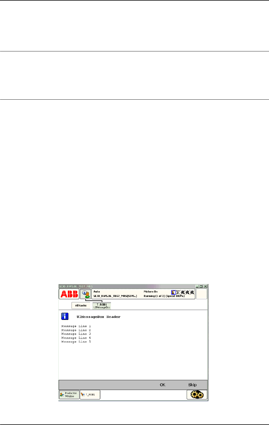
2 Functions
2.147. UIMessageBox - User Message Box type advanced
RobotWare - OS
10573HAC 16581-1 Revision: J
© Copyright 2004-2010 ABB. All rights reserved.
2.147. UIMessageBox - User Message Box type advanced
Usage
UIMessageBox (User Interaction Message Box) is used to communicate with the user of the
robot system on available user device, such as the FlexPendant. A message is written to the
operator, who answers by selecting a button. The user selection is then transferred back to the
program.
Basic examples
Basic examples of the function UIMessageBox are illustrated below.
See also More examples on page 1061.
Example 1
VAR btnres answer;
CONST string my_message{5}:= ["Message Line 1","Message Line 2",
"Message Line 3","Message Line 4","Message Line 5"];
CONST string my_buttons{2}:=["OK","Skip"];
...
answer:= UIMessageBox (
\Header:="UIMessageBox Header"
\MsgArray:=my_message
\BtnArray:=my_buttons
\Icon:=iconInfo);
IF answer = 1 THEN
! Operator selection OK
ELSEIF answer = 2 THEN
! Operator selection Skip
ELSE
! No such case defined
ENDIF
xx0500002409
Continues on next page

2 Functions
2.147. UIMessageBox - User Message Box type advanced
RobotWare - OS
3HAC 16581-1 Revision: J1058
© Copyright 2004-2010 ABB. All rights reserved.
Above message box is with icon, header, message, and user defined push buttons that are
written on the FlexPendant display. Program execution waits until OK or Skip is pressed. In
other words,
answer will be assigned 1 (OK) or 2 (Skip) depending on which of the buttons
is pressed (corresponding array index).
NOTE!
Message Line 1 ... Message Line 5 are displayed on separate lines 1 to 5 (the switch
\Wrap is not used).
Return value
Data type:
btnres
The numeric value of the button that is selected from the message box.
If argument
\Buttons is used, the predefined symbolic constants of type btnres is returned.
If argument
\BtnArray is used, the corresponding array index is returned.
If function breaks via
\BreakFlag or if \Buttons:=btnNone:
• If parameter \DefaultBtn is specified, this index is returned.
• If parameter \DefaultBtn is not specified, resUnkwn equal to 0 is returned.
If function breaks via
ERROR handler, there is no return value at all.
Arguments
UIMessageBox ( [\Header] [\Message] | [\MsgArray]
[\Wrap] [\Buttons] | [\BtnArray] [\DefaultBtn]
[\Icon] [\Image] [\MaxTime] [\DIBreak] [\DOBreak]
[\BreakFlag] )
[\Header]
Data type: string
Header text to be written at the top of the message box. Max. 40 characters.
[\Message]
Data type: string
One text line to be written on the display. Max 55 characters.
[\MsgArray]
Message Array
Data type:
string
Several text lines from an array to be written on the display.
Only one of parameter
\Message or \MsgArray can be used at the same time.
Max. layout space is 11 lines with 55 characters each.
[\Wrap]
Data type: switch
If selected, all the specified strings in the argument \MsgArray will be concatenated to one
string with single spaces between each individual string and spread out on as few lines as
possible.
Default, each string in the argument
\MsgArray will be on separate line on the display.
Continued
Continues on next page

2 Functions
2.147. UIMessageBox - User Message Box type advanced
RobotWare - OS
10593HAC 16581-1 Revision: J
© Copyright 2004-2010 ABB. All rights reserved.
[\Buttons]
Data type: buttondata
Defines the push buttons to be displayed. Only one of the predefined buttons combination of
type buttondata can be used. See Predefined data on page 1060.
Default, the system displays the OK button.
[\BtnArray]
Button Array
Data type:
string
Own definition of push buttons stored in an array of strings. This function returns the array
index when corresponding string is selected.
Only one of parameter
\Buttons or \BtnArray can be used at the same time.
Max. 5 buttons with 42 characters each.
[\DefaultBtn]
Default Button
Data type:
btnres
Allows to specify a value that should be returned if the message box is interrupted by
\MaxTime, \DIBreak, or \DOBreak. It’s possible to specify the predefined symbolic
constant of type
btnres or any user defined value. See Predefined data on page 1060.
[\Icon]
Data type: icondata
Defines the icon to be displayed. Only one of the predefined icons of type icondata can be
used. See Predefined data on page 1060.
Default, no icon.
[\Image]
Data type: string
The name of the image that should be used. To launch own images, the images has to be
placed in the
HOME: directory in the active system or directly in the active system.
The recommendation is to place the files in the
HOME: directory so that they are saved if a
Backup and Restore is done.
A warmstart is required and then the FlexPendant loads the images.
A demand on the system is that the RobotWare option FlexPendant Interface is used.
The image that will be shown can have the width of 185 pixels and the height of 300 pixels.
If the image is bigger, only 185 * 300 pixels of the image will be shown starting at the top left
of the image.
No exact value can be specified on the size that an image can have or the amount of images
that can be loaded to the FlexPendant. It depends on the size of other files loaded to the
FlexPendant. The program execution will just continue if an image is used that has not been
loaded to the FlexPendant.
Continued
Continues on next page

2 Functions
2.147. UIMessageBox - User Message Box type advanced
RobotWare - OS
3HAC 16581-1 Revision: J1060
© Copyright 2004-2010 ABB. All rights reserved.
[\MaxTime]
Data type: num
The maximum amount of time in seconds that program execution waits. If no button is
selected within this time, the program continues to execute in the error handler unless the
BreakFlag is used (see below). The constant ERR_TP_MAXTIME can be used to test whether
or not the maximum time has elapsed.
[\DIBreak]
Digital Input Break
Data type:
signaldi
The digital input signal that may interrupt the operator dialog. If no button is selected when
the signal is set to 1 (or is already 1) then the program continues to execute in the error
handler, unless the
BreakFlag is used (see below). The constant ERR_TP_DIBREAK can be
used to test whether or not this has occurred.
[\DOBreak]
Digital Output Break
Data type:
signaldo
The digital output signal that may interrupt the operator dialog. If no button is selected when
the signal is set to 1 (or is already 1) then the program continues to execute in the error
handler, unless the
BreakFlag is used (see below). The constant ERR_TP_DOBREAK can be
used to test whether or not this has occurred.
[\BreakFlag]
Data type: errnum
A variable (before used set to 0 by the system) that will hold the error code if \MaxTime,
\DIBreak, or \DOBreak is used. The constants ERR_TP_MAXTIME, ERR_TP_DIBREAK, and
ERR_TP_DOBREAK can be used to select the reason. If this optional variable is omitted, the
error handler will be executed.
Program execution
The message box with icon, header, message lines, image, and buttons are displayed
according to the programmed arguments. Program execution waits until the user selects one
button or the message box is interrupted by time-out or signal action. The user selection and
interrupt reason are transferred back to the program.
A new message box on TRAP level takes focus from message box on basic level.
Predefined data
!Icons:
CONST icondata iconNone := 0;
CONST icondata iconInfo := 1;
CONST icondata iconWarning := 2;
CONST icondata iconError := 3;
Continued
Continues on next page

2 Functions
2.147. UIMessageBox - User Message Box type advanced
RobotWare - OS
10613HAC 16581-1 Revision: J
© Copyright 2004-2010 ABB. All rights reserved.
!Buttons:
CONST buttondata btnNone := -1;
CONST buttondata btnOK := 0;
CONST buttondata btnAbrtRtryIgn := 1;
CONST buttondata btnOKCancel := 2;
CONST buttondata btnRetryCancel := 3;
CONST buttondata btnYesNo := 4;
CONST buttondata btnYesNoCancel := 5;
!Results:
CONST btnres resUnkwn := 0;
CONST btnres resOK := 1;
CONST btnres resAbort := 2;
CONST btnres resRetry := 3;
CONST btnres resIgnore := 4;
CONST btnres resCancel := 5;
CONST btnres resYes := 6;
CONST btnres resNo := 7;
More examples
More examples of the function
UIMessageBox are illustrated below.
Example 1
VAR errnum err_var;
VAR btnres answer;
...
answer := UIMessageBox (\Header:= "Cycle step 3"
\Message:="Continue with the calibration ?"
\Buttons:=btnOKCancel
\DefaultBtn:=resCancel \Icon:=iconInfo \MaxTime:=60
\DIBreak:=di5
\BreakFlag:=err_var);
IF answer = resOK THEN
! OK from the operator
ELSE
! Cancel from the operator or operation break
TEST err_var
CASE ERR_TP_MAXTIME:
! Time out
CASE ERR_TP_DIBREAK:
! Input signal break
DEFAULT:
! Not such case defined
ENDTEST
ENDIF
The message box is displayed, and the operator can answer OK or Cancel. The message box
can also be interrupted with time out or break by digital input signal. In the program it’s
possible to find out the reason.
Continued
Continues on next page

2 Functions
2.147. UIMessageBox - User Message Box type advanced
RobotWare - OS
3HAC 16581-1 Revision: J1062
© Copyright 2004-2010 ABB. All rights reserved.
Error handling
If parameter
\BreakFlag is not used, these situations can then be dealt with by the error
handler:
• If there is a time-out (parameter \MaxTime) before an input from the operator, the
system variable
ERRNO is set to ERR_TP_MAXTIME and the execution continues in the
error handler.
• If digital input is set (parameter \DIBreak) before an input from the operator, the
system variable
ERRNO is set to ERR_TP_DIBREAK and the execution continues in the
error handler.
• If a digital output is set (parameter \DOBreak) before an input from the operator, the
system variable
ERRNO is set to ERR_TP_DOBREAK and the execution continues in the
error handler.
This situation can only be dealt with by the error handler:
• If there is no client, e.g. a FlexPendant, to take care of the instruction, the system
variable
ERRNO is set to ERR_TP_NO_CLIENT and the execution continues in the error
handler.
Limitations
Avoid using too small a value for the time-out parameter
\MaxTime when UIMessageBox is
frequently executed, for example in a loop. It can result in an unpredictable behavior of the
system performance, like slow response of the FlexPendant.
Syntax
UIMessageBox´(´
[´\´Header´:=´ <expression (IN) of string>]
[´\´Message´:=´ <expression (IN) of string>]
| [´\´MsgArray´:=´<array {*} (IN) of string>]
[´\´Wrap]
[´\´Buttons´=´ <expression (IN) of buttondata>]
| [´\´BtnArray´:=´<array {*}(IN) of string>]
[‘\’DefaultBtn´:=´<expression (IN) of btnres>]
[‘\’Icon´:=´<expression (IN) of icondata>]
[‘\’Image´:=´<expression (IN) of string>]
[´\´MaxTime´:=´ <expression (IN) of num>]
[´\´DIBreak´:=´ <variable (VAR) of signaldi>]
[´\´DOBreak´:=´ <variable (VAR) of signaldo>]
[´\´BreakFlag´:=´ <var or pers (INOUT) of errnum>] ´)´
A function with return value of the data type btnres.
Continued
Continues on next page

2 Functions
2.147. UIMessageBox - User Message Box type advanced
RobotWare - OS
10633HAC 16581-1 Revision: J
© Copyright 2004-2010 ABB. All rights reserved.
Related information
For information about See
Icon display data icondata - Icon display data on page 1121
Push button data buttondata - Push button data on page 1089
Push button result data btnres - Push button result data on page 1086
User Interaction Message Box type basic UIMsgBox - User Message Dialog Box type basic
on page 644
User Interaction Number Entry UINumEntry - User Number Entry on page 1064
User Interaction Number Tune UINumTune - User Number Tune on page 1070
User Interaction Alpha Entry UIAlphaEntry - User Alpha Entry on page 1032
User Interaction List View UIListView - User List View on page 1050
System connected to FlexPendant etc. UIClientExist - Exist User Client on page 1037
FlexPendant interface Product Specification - Controller Software IRC5,
RobotWare 5.0, section Communication -
FlexPendant Interface
Clean up the Operator window TPErase - Erases text printed on the FlexPendant
on page 556
Continued
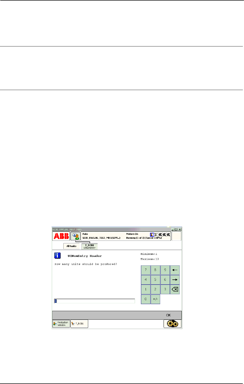
2 Functions
2.148. UINumEntry - User Number Entry
RobotWare - OS
3HAC 16581-1 Revision: J1064
© Copyright 2004-2010 ABB. All rights reserved.
2.148. UINumEntry - User Number Entry
Usage
UINumEntry (User Interaction Number Entry) is used to let the operator enter a numeric
value from the available user device, such as the FlexPendant. A message is written to the
operator, who answers with a numeric value. The numeric value is then checked, approved
and transferred back to the program.
Basic examples
Basic examples of the function
UINumEntry are illustrated below.
See also More examples on page 1067.
Example 1
VAR num answer;
...
answer := UINumEntry(
\Header:="UINumEntry Header"
\Message:="How many units should be produced?"
\Icon:=iconInfo
\InitValue:=5
\MinValue:=1
\MaxValue:=10
\AsInteger);
FOR i FROM 1 TO answer DO
produce_part;
ENDFOR
xx0500002412
Above numeric message box with icon, header, message, init-, max-, and minvalue are
written on the FlexPendant display. The message box checks that the operator selects an
integer within the value range. Program execution waits until OK is pressed and then the
selected numerical value is returned. The routine
produce_part is then repeated the number
of input times via the FlexPendant.
Continues on next page

2 Functions
2.148. UINumEntry - User Number Entry
RobotWare - OS
10653HAC 16581-1 Revision: J
© Copyright 2004-2010 ABB. All rights reserved.
Return value
Data type:
num
This function returns the input numeric value.
If function breaks via
\BreakFlag:
• If parameter \InitValue is specified, this value is returned
• If parameter \InitValue is not specified, value 0 is returned.
If function breaks via
ERROR handler, no return value at all.
Arguments
UINumEntry ( [\Header] [\Message] | [\MsgArray]
[\Wrap] [\Icon] [\InitValue] [\MinValue] [\MaxValue]
[\AsInteger] [\MaxTime] [\DIBreak] [\DOBreak]
\BreakFlag] )
[\Header]
Data type: string
Header text to be written at the top of the message box. Max. 40 characters.
[\Message]
Data type: string
One text line to be written on the display. Max 40 characters.
[\MsgArray]
Message Array
Data type:
string
Several text lines from an array to be written on the display.
Only one of parameter
\Message or \MsgArray can be used at the same time.
Max. layout space is 9 lines with 40 characters each.
[\Wrap]
Data type: switch
If selected, all the specified strings in the argument \MsgArray will be concatenated to one
string with a single space between each individual string, and spread out on as few lines as
possible.
Default, each string in the argument
\MsgArray will be on a separate line on the display.
[\Icon]
Data type: icondata
Defines the icon to be displayed. Only one of the predefined icons of type icondata can be
used. See Predefined data on page 1067.
Default no icon.
[\InitValue]
Data type: num
Initial value that is displayed in the entry box.
Continued
Continues on next page

2 Functions
2.148. UINumEntry - User Number Entry
RobotWare - OS
3HAC 16581-1 Revision: J1066
© Copyright 2004-2010 ABB. All rights reserved.
[\MinValue]
Data type: num
The minimum value for the return value.
[\MaxValue]
Data type: num
The maximum value for the return value.
[\AsInteger]
Data type: switch
Eliminates the decimal point from the number pad to ensure that the return value is an integer.
[\MaxTime]
Data type: num
The maximum amount of time in seconds that program execution waits. If the OK button is
not pressed within this time, the program continues to execute in the error handler unless the
BreakFlag is used (see below). The constant ERR_TP_MAXTIME can be used to test whether
or not the maximum time has elapsed.
[\DIBreak]
Digital Input Break
Data type:
signaldi
The digital input signal that may interrupt the operator dialog. If the OK button is not pressed
before the signal is set to 1 (or is already 1) then the program continues to execute in the error
handler, unless the
BreakFlag is used (see below). The constant ERR_TP_DIBREAK can be
used to test whether or not this has occurred.
[\DOBreak]
Digital Output Break
Data type:
signaldo
The digital output signal that may interrupt the operator dialog. If the OK button is not pressed
before the signal is set to 1 (or is already 1) then the program continues to execute in the error
handler, unless the
BreakFlag is used (see below). The constant ERR_TP_DOBREAK can be
used to test whether or not this has occurred.
[\BreakFlag]
Data type: errnum
A variable (before used set to 0 by the system) that will hold the error code if \MaxTime,
\DIBreak, or \DOBreak is used. The constants ERR_TP_MAXTIME, ERR_TP_DIBREAK, and
ERR_TP_DOBREAK can be used to select the reason. If this optional variable is omitted, the
error handler will be executed.
Continued
Continues on next page

2 Functions
2.148. UINumEntry - User Number Entry
RobotWare - OS
10673HAC 16581-1 Revision: J
© Copyright 2004-2010 ABB. All rights reserved.
Program execution
The numeric message box with numeric pad, icon, header, message lines, init-, max-, and
minvalue are displayed according to the programmed arguments. Program execution waits
until the user has entered an approved numeric value and presses OK or the message box is
interrupted by time-out or signal action. The input numeric value and interrupt reason are
transferred back to the program.
New message box on TRAP level take focus from message box on basic level.
Predefined data
!Icons:
CONST icondata iconNone := 0;
CONST icondata iconInfo := 1;
CONST icondata iconWarning := 2;
CONST icondata iconError := 3;
More examples
More examples of the function
UINumEntry are illustrated below.
Example 1
VAR errnum err_var;
VAR num answer;
VAR num distance;
...
answer := UINumEntry (\Header:= "BWD move on path"
\Message:="Enter the path overlap ?" \Icon:=iconInfo
\InitValue:=5 \MinValue:=0 \MaxValue:=10
\MaxTime:=60 \DIBreak:=di5 \BreakFlag:=err_var);
TEST err_var
CASE ERR_TP_MAXTIME:
CASE ERR_TP_DIBREAK:
! No operator answer distance := 5;
CASE 0
! Operator answer
distance := answer;
DEFAULT:
! Not such case defined
ENDTEST
The message box is displayed and the operator can enter a numeric value and press OK. The
message box can also be interrupted with a time out or break by digital input signal. In the
program it’s possible to find out the reason and take the appropriate action.
Continued
Continues on next page

2 Functions
2.148. UINumEntry - User Number Entry
RobotWare - OS
3HAC 16581-1 Revision: J1068
© Copyright 2004-2010 ABB. All rights reserved.
Error handling
If parameter
\BreakFlag is not used, these situations can then be dealt with by the error
handler:
• If there is a time-out (parameter \MaxTime) before an input from the operator then the
system variable
ERRNO is set to ERR_TP_MAXTIME and the execution continues in the
error handler.
• If digital input is set (parameter \DIBreak) before an input from the operator then the
system variable
ERRNO is set to ERR_TP_DIBREAK and the execution continues in the
error handler.
• If a digital output is set (parameter \DOBreak) before an input from the operator then
the system variable
ERRNO is set to ERR_TP_DOBREAK and the execution continues in
the error handler.
This situation can only be dealt with by the error handler:
• If there is no client, e.g. a FlexPendant, to take care of the instruction then the system
variable
ERRNO is set to ERR_TP_NO_CLIENT and the execution continues in the error
handler.
• If the initial value (parameter \InitValue) is not specified within the range of the
minimum and maximum value (parameters
\MinValue and \MaxValue) then the
system variable
ERRNO is set to ERR_UI_INITVALUE and the execution continues in
the error handler.
• If the minimum value (parameter \MinValue) is greater then the maximum value
(parameter
\MaxValue) then the system variable ERRNO is set to ERR_UI_MAXMIN
and the execution continues in the error handler.
• If the initial value (parameter \InitValue) is not an integer as specified in the
parameter
\AsInteger then the system variable ERRNO is set to ERR_UI_NOTINT
and the execution continues in the error handler.
Limitations
Avoid using too small a value for the time-out parameter
\MaxTime when UINumEntry is
frequently executed, for example in a loop. It can result in unpredictable behavior from the
system performance, like slow response of the FlexPendant.
Continued
Continues on next page

2 Functions
2.148. UINumEntry - User Number Entry
RobotWare - OS
10693HAC 16581-1 Revision: J
© Copyright 2004-2010 ABB. All rights reserved.
Syntax
UINumEntry´(´
[´\´Header´:=´ <expression (IN) of string>]
[Message’:=’ <expression (IN) of string> ]
| [´\´MsgArray’:=’<array {*} (IN) of string>]
[´\´Wrap]
[´\´Icon’:=’ <expression (IN) of icondata>]
[´\´InitValue’:=’<expression (IN) of num>]
[´\´MinValue’:=’<expression (IN) of num>]
[´\´MaxValue’:=’<expression (IN) of num>]
[´\´AsInteger]
[´\´MaxTime’:=’ <expression (IN) of num>]
[\´DIBreak’:=’ <variable (VAR) of signaldi>]
[´\´DOBreak’:=’ <variable (VAR) of signaldo>]
[´\´BreakFlag’:=’ <var or pers (INOUT) of errnum>] ´)´
A function with return value of the data type num.
Related information
For information about See
Icon display data icondata - Icon display data on page 1121
User Interaction Message Box type basic UIMsgBox - User Message Dialog Box type
basic on page 644
User Interaction Message Box type advanced UIMessageBox - User Message Box type
advanced on page 1057
User Interaction Number Tune UINumTune - User Number Tune on page
1070
User Interaction Alpha Entry UIAlphaEntry - User Alpha Entry on page
1032
User Interaction List View UIListView - User List View on page 1050
System connected to FlexPendant etc. UIClientExist - Exist User Client on page
1037
Clean up the Operator window TPErase - Erases text printed on the
FlexPendant on page 556
Continued
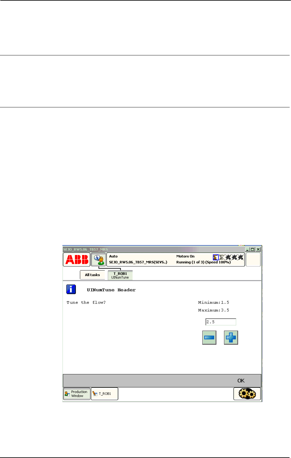
2 Functions
2.149. UINumTune - User Number Tune
RobotWare - OS
3HAC 16581-1 Revision: J1070
© Copyright 2004-2010 ABB. All rights reserved.
2.149. UINumTune - User Number Tune
Usage
UINumTune (User Interaction Number Tune) is used to let the operator tune a numeric value
from the available user device, such as the FlexPendant. A message is written to the operator,
who tunes a numeric value. The tuned numeric value is then checked, approved and
transferred back to the program.
Basic examples
Basic examples of the function
UINumTune are illustrated below.
See also More examples on page 1073.
Example 1
VAR num flow;
...
flow := UINumTune(
\Header:="UINumTune Header"
\Message:="Tune the flow?"
\Icon:=iconInfo,
2.5,
0.1
\MinValue:=1.5
\MaxValue:=3.5);
xx0500002414
Continues on next page

2 Functions
2.149. UINumTune - User Number Tune
RobotWare - OS
10713HAC 16581-1 Revision: J
© Copyright 2004-2010 ABB. All rights reserved.
Above numeric tune message box with icon, header, message, init-, increment, max-, and
minvalue are written on the FlexPendant display. The message box checks that the operator
tune the
flow value with step 0.1 from init value 2.5 is within the value range 1.5 .. 3.5.
Program execution waits until OK is pressed and then the selected numerical value is returned
and stored in the variable
flow.
Return value
Data type:
num
This function returns the tuned numeric value.
If function breaks via
\BreakFlag, the specified InitValue is returned.
If function breaks via
ERROR handler, no return value is returned at all.
Arguments
UINumTune ( [\Header] [\Message] | [\MsgArray] [\Wrap]
[\Icon] InitValue Increment [\MinValue] [\MaxValue]
[\MaxTime] [\DIBreak] [\DOBreak] [\BreakFlag] )
[\Header]
Data type: string
Header text to be written at the top of the message box. Max. 40 characters.
[\Message]
Data type: string
One text line to be written on the display. Max 40 characters.
[\MsgArray]
Message Array
Data type:
string
Several text lines from an array to be written on the display.
Only one of parameter
\Message or \MsgArray can be used at the same time.
Max. layout space is 11 lines with 40 characters each.
[\Wrap]
Data type: switch
If selected, all the specified strings in the argument \MsgArray will be concatenated to one
string with a single space between each individual string and spread out on as few lines as
possible.
Default, each string in the argument
\MsgArray will be on separate line on the display.
[\Icon]
Data type: icondata
Defines the icon to be displayed. Only one of the predefined icons of type icondata can be
used. See Predefined data on page 1073.
Default no icon.
Continued
Continues on next page

2 Functions
2.149. UINumTune - User Number Tune
RobotWare - OS
3HAC 16581-1 Revision: J1072
© Copyright 2004-2010 ABB. All rights reserved.
InitValue
Initial Value
Data type:
num
Initial value that is displayed in the entry box.
Increment
Data type: num
This parameter specifies how much the value should change when the plus or minus button
is pressed.
[\MinValue]
Data type: num
The minimum value for the return value.
[\MaxValue]
Data type: num
The maximum value for the return value.
[\MaxTime]
Data type: num
The maximum amount of time in seconds that program execution waits. If the OK button is
not pressed within this time, the program continues to execute in the error handler unless the
BreakFlag is used (see below). The constant ERR_TP_MAXTIME can be used to test whether
or not the maximum time has elapsed.
[\DIBreak]
Digital Input Break
Data type:
signaldi
The digital input signal that may interrupt the operator dialog. If the OK button is not pressed
before the signal is set to 1 (or is already 1) then the program continues to execute in the error
handler, unless the
BreakFlag is used (see below). The constant ERR_TP_DIBREAK can
be used to test whether or not this has occurred.
[\DOBreak]
Digital Output Break
Data type:
signaldo
The digital output signal that may interrupt the operator dialog. If the OK button is not pressed
before the signal is set to 1 (or is already 1) then the program continues to execute in the error
handler, unless the
BreakFlag is used (see below). The constant ERR_TP_DOBREAK can be
used to test whether or not this has occurred.
[\BreakFlag]
Data type: errnum
A variable (before used set to 0 by the system) that will hold the error code if \MaxTime,
\DIBreak, or \DOBreak is used. The constants ERR_TP_MAXTIME, ERR_TP_DIBREAK, and
ERR_TP_DOBREAK can be used to select the reason. If this optional variable is omitted, the
error handler will be executed.
Continued
Continues on next page

2 Functions
2.149. UINumTune - User Number Tune
RobotWare - OS
10733HAC 16581-1 Revision: J
© Copyright 2004-2010 ABB. All rights reserved.
Program execution
The numeric tune message box with tune +/- buttons, icon, header, message lines, init-,
increment, max, and minvalue are displayed according to the programmed arguments.
Program execution waits until the user has tuned the numeric value and pressed OK or the
message box is interrupted by time-out or signal action. The input numeric value and interrupt
reason are transferred back to the program.
New message box on
TRAP level takes focus from message box on basic level.
Predefined data
!Icons:
CONST icondata iconNone := 0;
CONST icondata iconInfo := 1;
CONST icondata iconWarning := 2;
CONST icondata iconError := 3;
More examples
More examples of the function
UINumTune are illustrated below.
Example 1
VAR errnum err_var;
VAR num tune_answer;
VAR num distance;
...
tune_answer := UINumTune (\Header:=" BWD move on path"
\Message:="Enter the path overlap ?" \Icon:=iconInfo,
5, 1 \MinValue:=0 \MaxValue:=10
\MaxTime:=60 \DIBreak:=di5 \BreakFlag:=err_var);
TEST err_var
CASE ERR_TP_MAXTIME:
CASE ERR_TP_DIBREAK:
! No operator answer
distance := 5;
CASE 0:
! Operator answer
distance := tune_answer;
DEFAULT:
! Not such case defined
ENDTEST
The tune message box is displayed and the operator can tune the numeric value and press OK.
The message box can also be interrupted with time-out or break by digital input signal. In the
program it’s possible to find out the reason and take the appropriate action.
Continued
Continues on next page

2 Functions
2.149. UINumTune - User Number Tune
RobotWare - OS
3HAC 16581-1 Revision: J1074
© Copyright 2004-2010 ABB. All rights reserved.
Error handling
If parameter
\BreakFlag is not used then these situations can be dealt with by the error
handler:
• If there is a time-out (parameter \MaxTime) before an input from the operator, the
system variable
ERRNO is set to ERR_TP_MAXTIME and the execution continues in the
error handler.
• If digital input is set (parameter \DIBreak) before an input from the operator, the
system variable
ERRNO is set to ERR_TP_DIBREAK and the execution continues in the
error handler.
• If a digital output is set (parameter \DOBreak) before an input from the operator, the
system variable
ERRNO is set to ERR_TP_DOBREAK and the execution continues in the
error handler.
This situation can only be dealt with by the error handler:
• If there is no client, e.g. a FlexPendant, to take care of the instruction then the system
variable
ERRNO is set to ERR_TP_NO_CLIENT and the execution continues in the error
handler.
• If the initial value (parameter \InitValue) is not specified within the range of the
minimum and maximum value (parameters
\MinValue and \MaxValue) then the
system variable
ERRNO is set to ERR_UI_INITVALUE and the execution continues in
the error handler.
• If the minimum value (parameter \MinValue) is greater than the maximum value
(parameter
\MaxValue) then the system variable ERRNO is set to ERR_UI_MAXMIN
and the execution continues in the error handler.
Limitations
Avoid using too small a value for the time-out parameter
\MaxTime when UINumTune is
frequently executed, for example in a loop. It can result in unpredictable behavior from the
system performance, like slow response of the FlexPendant.
Syntax
UINumTune’(’
[’\’Header’:=’ <expression (IN) of string>]
[’\’Message’:=’ <expression (IN) of string> ]
| [‘\’MsgArray’:=’<array {*} (IN) of string>]
[’\’Wrap]
[’\’Icon’:=’ <expression (IN) of icondata>] ’,’]
[InitValue’:=’ ] <expression (IN) of num> ’,’
[Increment’:=’ ] <expression (IN) of num>
[’\’MinValue’:=’<expression (IN) of num>]
[’\’MaxValue’:=’<expression(IN) of num>]
[’\’MaxTime’:=’ <expression (IN) of num>]
[’\’DIBreak’:=’ <variable (VAR) of signaldi>]
[’\’DOBreak’:=’ <variable (VAR) of signaldo>]
[’\’BreakFlag’:=’ <var or pers (INOUT) of errnum>] ’)’
A function with return value of the data type num.
Continued
Continues on next page

2 Functions
2.149. UINumTune - User Number Tune
RobotWare - OS
10753HAC 16581-1 Revision: J
© Copyright 2004-2010 ABB. All rights reserved.
Related information
For information about See
Icon display data icondata - Icon display data on page 1121
User Interaction Message Box type basic UIMsgBox - User Message Dialog Box type
basic on page 644
User Interaction Message Box type advanced UIMessageBox - User Message Box type
advanced on page 1057
User Interaction Number Entry UINumEntry - User Number Entry on page
1064
User Interaction Alpha Entry UIAlphaEntry - User Alpha Entry on page
1032
User Interaction List View UIListView - User List View on page 1050
System connected to FlexPendant etc. UIClientExist - Exist User Client on page
1037
Clean up the Operator window TPErase - Erases text printed on the
FlexPendant on page 556
Continued

2 Functions
2.150. ValidIO - Valid I/O signal to access
RobotWare - OS
3HAC 16581-1 Revision: J1076
© Copyright 2004-2010 ABB. All rights reserved.
2.150. ValidIO - Valid I/O signal to access
Usage
ValidIO is used to check if the specified I/O signal can be accessed without any error at
present.
Basic examples
Basic examples of the function
ValidIO are illustrated below.
Example 1
IF ValidIO(mydosignal) SetDO mydosignal, 1;
Set the digital output signal mydosignal to 1 if it’s I/O unit is up and running.
Return value
Data type:
bool
Returns TRUE is valid signal and the I/O unit for the signal is up and running, else FALSE.
Arguments
ValidIO (Signal)
Signal
Data type: signalxx
The signal name. Must be of data type signaldo, signaldi, signalgo, signalgi,
signalao
or signalai.
Program execution
Execution behaviour:
• Check if valid I/O signal
• Check if the I/O unit for the signal is up and running.
No error messages are generated.
Syntax
ValidIO ’(’
[Signal ’:=’] <variable (VAR) of anytype>
’)’
A function with a return value of the data type bool.
Continues on next page

2 Functions
2.150. ValidIO - Valid I/O signal to access
RobotWare - OS
10773HAC 16581-1 Revision: J
© Copyright 2004-2010 ABB. All rights reserved.
Related information
For information about See
Input/Output instructions Technical reference manual - RAPID
overview, section RAPID Summary - Input
and Output Signals
Input/Output functionality in general Technical reference manual - RAPID
overview, section Motion and I/O Principles -
I/O Principles
Configuration of I/O Technical reference manual - System
parameters
Define I/O signal with alias name AliasIO - Define I/O signal with alias name on
page 21
Continued

2 Functions
2.151. ValToStr - Converts a value to a string
RobotWare - OS
3HAC 16581-1 Revision: J1078
© Copyright 2004-2010 ABB. All rights reserved.
2.151. ValToStr - Converts a value to a string
Usage
ValToStr (Value To String) is used to convert a value of any data type to a string.
Basic examples
Basic examples of the function
ValToStr are illustrated below.
Example 1
VAR string str;
VAR pos p := [100,200,300];
str := ValToStr(p);
The variable str is given the value "[100,200,300]".
Example 2
str := ValToStr(TRUE);
The variable str is given the value "TRUE".
Example 3
str := ValToStr(1.234567890123456789);
The variable str is given the value "1.23456789012346".
Example 4
VAR num numtype:=1.234567890123456789;
str := ValToStr(numtype);
The variable str is given the value "1.23457".
Example 5
VAR dnum dnumtype:=1.234567890123456789;
str := ValToStr(dnumtype);
The variable str is given the value "1.23456789012346".
Return value
Data type:
string
The value is converted to a string with standard RAPID format. This means, in principle, 6
significant digits. Literal value interpreted as a
dnum (see example 3) and dnum variabels (see
example 5) though have 15 significant digits.
A runtime error is generated if the resulting string is too long.
Continues on next page

2 Functions
2.151. ValToStr - Converts a value to a string
RobotWare - OS
10793HAC 16581-1 Revision: J
© Copyright 2004-2010 ABB. All rights reserved.
Arguments
ValToStr ( Val )
Val
Va lue
Data type:
anytype
A value of any data type. All types of value data with structure atomic, record, record
component, array, or array element can be used.
Syntax
ValToStr’(’
[ Val ’:=’ ] <expression (IN) of anytype>
’)’
A function with a return value of the data type string.
Related information
For information about See
String functions Technical reference manual - RAPID overview, section
RAPID summary - String functions
Definition of string string - Strings on page 1195
String values Technical reference manual - RAPID overview, section
Basic characteristics - Basic elements
Continued
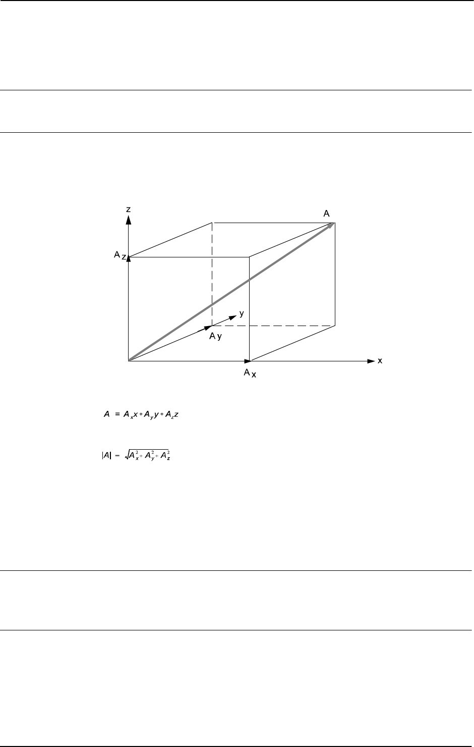
2 Functions
2.152. VectMagn - Magnitude of a pos vector
RobotWare - OS
3HAC 16581-1 Revision: J1080
© Copyright 2004-2010 ABB. All rights reserved.
2.152. VectMagn - Magnitude of a pos vector
Usage
VectMagn (Vector Magnitude) is used to calculate the magnitude of a pos vector.
Basic examples
Basic examples of the function
VectMagn are illustrated below.
Example 1
xx0500002446
A vector A can be written as the sum of its components in the three orthogonal directions:
.
The magnitude of A is:
.
The vector is described by the data type pos and the magnitude by the data type num:
VAR num magnitude;
VAR pos vector;
...
vector := [1,1,1];
magnitude := VectMagn(vector);
Return value
Data type:
num
The magnitude of the vector (data type pos).
Arguments
VectMagn (Vector)
Vector
Data type: pos
The vector described by the data type pos.
Continues on next page

2 Functions
2.152. VectMagn - Magnitude of a pos vector
RobotWare - OS
10813HAC 16581-1 Revision: J
© Copyright 2004-2010 ABB. All rights reserved.
Syntax
VectMagn’(’
[Vector ’:=’] <expression (IN) of pos>
’)’
A function with a return value of the data type num.
Related information
For information about See
Mathematical instructions and functions Technical reference manual - RAPID
overview, section RAPID summary -
Mathematics
Continued

2 Functions
2.152. VectMagn - Magnitude of a pos vector
RobotWare - OS
3HAC 16581-1 Revision: J1082
© Copyright 2004-2010 ABB. All rights reserved.

3 Data types
3.1. aiotrigg - Analog I/O trigger condition
RobotWare - OS
10833HAC 16581-1 Revision: J
© Copyright 2004-2010 ABB. All rights reserved.
3 Data types
3.1. aiotrigg - Analog I/O trigger condition
Usage
aiotrigg (Analog I/O Trigger) is used to define the condition to generate an interrupt for an
analog input or output signal.
Description
Data of the type
aiotrigg defines the way a low and a high threshold will be used to
determine whether the logical value of an analog signal satisfies a condition to generate an
interrupt.
Basic examples
Basic examples of the data type
aiotrigg are illustrated below.
Example 1
VAR intnum sig1int;
CONNECT sig1int WITH iroutine1;
ISignalAI \Single, ai1, AIO_BETWEEN, 1.5, 0.5, 0, sig1int;
Orders an interrupt which is to occur the first time the logical value of the analog input signal
ai1 is between 0.5 and 1.5. A call is then made to the iroutine1 trap routine.
Predefined data
The following symbolic constants of the data type
aiotrigg are predefined and can be used
when specifying a condition for the instructions
ISignalAI and ISignalAO.
Characteristics
aiotrigg is an alias data type for num and consequently inherits its characteristics.
Value Symbolic constant Comment
1 AIO_ABOVE_HIGH Signal will generate interrupts if above specified high value
2 AIO_BELOW_HIGH Signal will generate interrupts if below specified high value
3 AIO_ABOVE_LOW Signal will generate interrupts if above specified low value
4 AIO_BELOW_LOW Signal will generate interrupts if below specified low value
5 AIO_BETWEEN Signal will generate interrupts if between specified low and
high values
6 AIO_OUTSIDE Signal will generate interrupts if below specified low value
or above specified high value
7 AIO_ALWAYS Signal will always generate interrupts
Continues on next page

3 Data types
3.1. aiotrigg - Analog I/O trigger condition
RobotWare - OS
3HAC 16581-1 Revision: J1084
© Copyright 2004-2010 ABB. All rights reserved.
Related information
For information about See
Interrupt from analog input signal ISignalAI - Interrupts from analog input signal on
page 171
Interrupt from analog output signal ISignalAO - Interrupts from analog output signal
on page 182
Data types in general, alias data types Technical reference manual - RAPID overview,
section Basic characteristics - Data types
Continued

3 Data types
3.2. bool - Logical values
RobotWare - OS
10853HAC 16581-1 Revision: J
© Copyright 2004-2010 ABB. All rights reserved.
3.2. bool - Logical values
Usage
bool is used for logical values (true/false).
Description
The value of data of the type
bool can be either TRUE or FALSE.
Basic examples
Basic examples of the data type
bool are illustrated below.
Example 1
flag1 := TRUE;
flag is assigned the value TRUE.
Example 2
VAR bool highvalue;
VAR num reg1;
...
highvalue := reg1 > 100;
highvalue
is assigned the value TRUE if reg1 is greater than 100; otherwise, FALSE is
assigned.
Example 3
IF highvalue Set do1;
The do1 signal is set if highvalue is TRUE.
Example 4
highvalue := reg1 > 100;
mediumvalue := reg1 > 20 AND NOT highvalue;
mediumvalue
is assigned the value TRUE if reg1 is between 20 and 100.
Related information
For information about See
Logical expressions Technical reference manual - RAPID overview,
section Basic characteristics - Expressions
Operations using logical values Technical reference manual - RAPID overview,
section Basic characteristics - Expressions

3 Data types
3.3. btnres - Push button result data
RobotWare - OS
3HAC 16581-1 Revision: J1086
© Copyright 2004-2010 ABB. All rights reserved.
3.3. btnres - Push button result data
Usage
btnres (button result) is used for representing the user selection of the push button display
on the User Device such as the FlexPendant.
Description
A
btnres constant is intended to be used when checking the result value from the instruction
UIMsgBox and the return value from the functions UIMessageBox and UIListView.
Basic examples
Basic examples of the data type
btnres are illustrated below.
Example 1
VAR btnres answer;
UIMsgBox "More ?" \Buttons:=btnYesNo \Result:= answer;
IF answer= resYes THEN
...
ELSEIF answer =ResNo THEN
...
ENDIF
The standard button enumeration btnYesNo will give one Yes and one No push button on the
user interface. The user selection will be stored in the variable
answer.
Predefined data
The following constants of the data type
btnres are predefined in the system
It is possible to work with user defined push buttons that answer with the functions
UIMessageBox and UIListView.
Characteristics
btnres is an alias data type for num and consequently inherits its characteristics.
Value Constants Button answer
0 resUnkwn Unknown result
1 resOK OK
2 resAbort Abort
3 resRetry Retry
4 resIgnore Ignore
5 resCancel Cancel
6 resYes Yes
7 resNo No
Continues on next page

3 Data types
3.3. btnres - Push button result data
RobotWare - OS
10873HAC 16581-1 Revision: J
© Copyright 2004-2010 ABB. All rights reserved.
Related information
For information about See
User Interaction Message Box UIMsgBox - User Message Dialog Box type basic on
page 644
User Interaction Message Box UIMessageBox - User Message Box type advanced
on page 1057
User Interaction List View UIListView - User List View on page 1050
Alias data type button data buttondata - Push button data on page 1089
Continued

3 Data types
3.4. busstate - State of I/O bus
RobotWare - OS
3HAC 16581-1 Revision: J1088
© Copyright 2004-2010 ABB. All rights reserved.
3.4. busstate - State of I/O bus
Usage
busstate is used to mirror which state an I/O bus is currently in.
Description
A
busstate constant is intended to be used when checking the return value from the
instruction
IOBusState.
Basic examples
Basic example of the data type
busstate is illustrated below.
Example 1
VAR busstate bstate;
IOBusState "IBS", bstate \Phys;
TEST bstate
CASE IOBUS_PHYS_STATE_RUNNING:
! Possible to access some signal on the IBS bus
DEFAULT:
! Actions for not up and running IBS bus
ENDTEST
Predefined data
The predefined symbolic constants of the data type
busstate can be viewed in instruction
IOBusState.
Characteristics
busstate is an alias data type for num and consequently inherits its characteristics.
Related information
For information about See
Get current state of I/O bus IOBusState - Get current state of I/O bus on page 156
Input/Output instructions Technical reference manual - RAPID overview,
section RAPID Summary - Input and Output Signals
Input/Output functionality in general Technical reference manual - RAPID overview,
section Motion and I/O Principles - I/O Principles
Configuration of I/O Technical reference manual - System parameters

3 Data types
3.5. buttondata - Push button data
RobotWare - OS
10893HAC 16581-1 Revision: J
© Copyright 2004-2010 ABB. All rights reserved.
3.5. buttondata - Push button data
Usage
buttondata is used for representing a standard push button combination for display on the
User Device such as the FlexPendant.
Description
A
buttondata constant is used for representing response push buttons in instruction
UIMsgBox and functions UIMessageBox and UIListView.
Basic examples
Basic examples of the data type
buttondata are illustrated below.
Example 1
VAR btnres answer;
UIMsgBox "More ?" \Buttons:=btnYesNo \Result:= answer;
IF answer= resYes THEN
...
ELSE
...
ENDIF
The standard button enumeration btnYesNo will give one Yes and one No push button.
Predefined data
The following constants of the data type
buttondata are predefined in the system.
It is possible to display user defined push buttons with the functions
UIMessageBox and
UIListView.
Characteristics
buttondata is an alias data type for num and consequently inherits its characteristics.
Value Constants Button displayed
- 1 btnNone No button
0 btnOK OK
1 btnAbrtRtryIgn Abort, Retry and Ignore
2 btnOKCancel OK and Cancel
3 btnRetryCancel Retry and Cancel
4 btnYesNo Yes and No
5 btnYesNoCancel Yes, No and Cancel
Continues on next page

3 Data types
3.5. buttondata - Push button data
RobotWare - OS
3HAC 16581-1 Revision: J1090
© Copyright 2004-2010 ABB. All rights reserved.
Related information
For information about See
User Interaction Message Box UIMsgBox - User Message Dialog Box type
basic on page 644
User Interaction Message Box UIMessageBox - User Message Box type
advanced on page 1057
User Interaction List View UIListView - User List View on page 1050
Alias data type button result btnres - Push button result data on page 1086
Data types in general, alias data types Technical reference manual - RAPID overview,
section Basic Characteristics - Data Types
Continued

3 Data types
3.6. byte - Integer values 0 - 255
RobotWare - OS
10913HAC 16581-1 Revision: J
© Copyright 2004-2010 ABB. All rights reserved.
3.6. byte - Integer values 0 - 255
Usage
byte is used for integer values (0 - 255) according to the range of a byte.
This data type is used in conjunction with instructions and functions that handle the bit
manipulations and convert features.
Description
Data of the type
byte represents an integer byte value.
Basic examples
Basic examples of the data type
byte are illustrated below.
Example 1
VAR byte data1 := 130;
Definition of a variable data1 with a decimal value 130.
Example 2
CONST num parity_bit := 8;
VAR byte data1 := 130;
BitClear data1, parity_bit;
Bit number 8 (parity_bit) in the variable data1 will be set to 0, e.g. the content of the
variable
data1 will be changed from 130 to 2 (integer representation).
Error handling
If an argument of the type
byte has a value that is not in the range between 0 and 255, an
error is returned on program execution.
Characteristics
byte is an alias data type for num and consequently inherits its characteristics.
Related information
For information about See
Alias data types Technical reference manual - RAPID overview,
section Basic characteristics - Data types
Bit functions Technical reference manual - RAPID overview,
section RAPID summary - Bit functions

3 Data types
3.7. clock - Time measurement
RobotWare - OS
3HAC 16581-1 Revision: J1092
© Copyright 2004-2010 ABB. All rights reserved.
3.7. clock - Time measurement
Usage
Clock is used for time measurement. A clock functions like a stopwatch used for timing.
Description
Data of the type
clock stores a time measurement in seconds and has a resolution of
0.01 seconds.
Basic examples
Basic examples of the data type
clock are illustrated below.
Example 1
VAR clock myclock;
ClkReset myclock;
The clock, myclock, is declared and reset. Before using ClkReset, ClkStart, ClkStop,
and
ClkRead, you must declare a variable of data type clock in your program.
Limitations
The maximum time that can be stored in a clock variable is approximately 49 days (4,294,967
seconds). The instructions
ClkStart, ClkStop, and ClkRead report clock overflows in the
very unlikely event that one occurs.
A clock must be declared as a
VAR variable type, not as a persistent variable type.
Characteristics
clock is a non-value data type and cannot be used in value-oriented operations.
Related information
For information about See
Summary of Time and Date Instructions Technical reference manual - RAPID overview,
section RAPID summary - System & time
Non-value data type characteristics Technical reference manual - RAPID overview,
section Basic characteristics - Data types
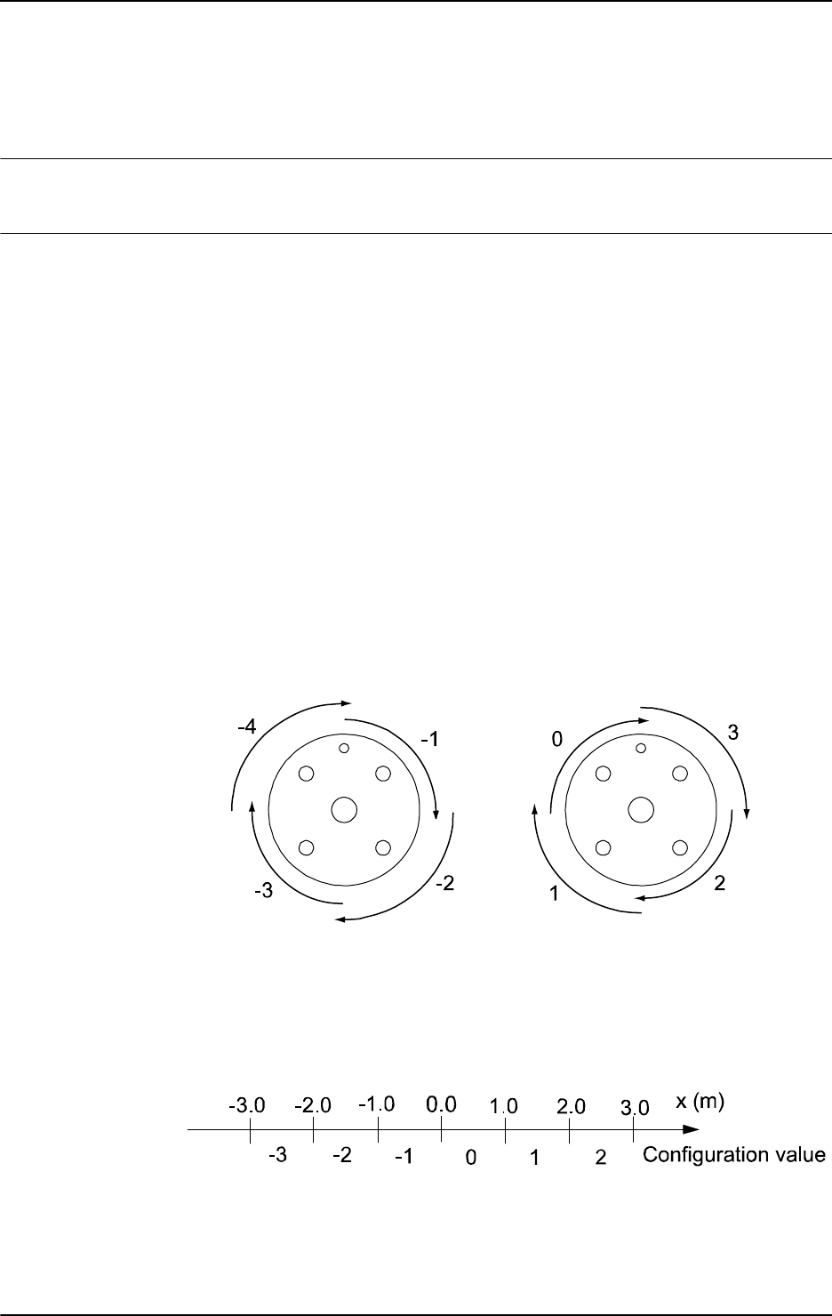
3 Data types
3.8. confdata - Robot configuration data
RobotWare - OS
10933HAC 16581-1 Revision: J
© Copyright 2004-2010 ABB. All rights reserved.
3.8. confdata - Robot configuration data
Usage
confdata is used to define the axis configurations of the robot.
Description
All positions of the robot are defined and stored using rectangular coordinates. When
calculating the corresponding axis positions, there will often be two or more possible
solutions. This means that the robot is able to achieve the same position, i.e. the tool is in the
same position and with the same orientation with several different positions or configurations
of the robots axes.
Some robot types use iterative numerical methods to determine the robot axes positions. In
these cases the configuration parameters may be used to define good starting values for the
joints to be used by the iterative procedure.
To unambiguously denote one of these possible configurations, the robot configuration is
specified using four axis values. For a rotating axis, the value defines the current quadrant of
the robot axis. The quadrants are numbered 0, 1, 2, etc. (they can also be negative). The
quadrant number is connected to the current joint angle of the axis. For each axis, quadrant 0
is the first quarter revolution, 0 to 90°, in a positive direction from the zero position; quadrant
1 is the next revolution, 90 to 180°, etc. Quadrant -1 is the revolution 0° to (-90°), etc. (see
figure below).
The figure shows the configuration quadrants for axis 6.
xx0500002398
For a linear axis, the value defines a meter interval for the robot axis. For each axis, value 0
means a position between 0 and 1 meters and 1 means a position between 1 and 2 meters. For
negative values, -1 means a position between -1 and 0 meters, etc. (see figure below).
The figure shows configuration values for a linear axis.
xx0500002399
Continues on next page
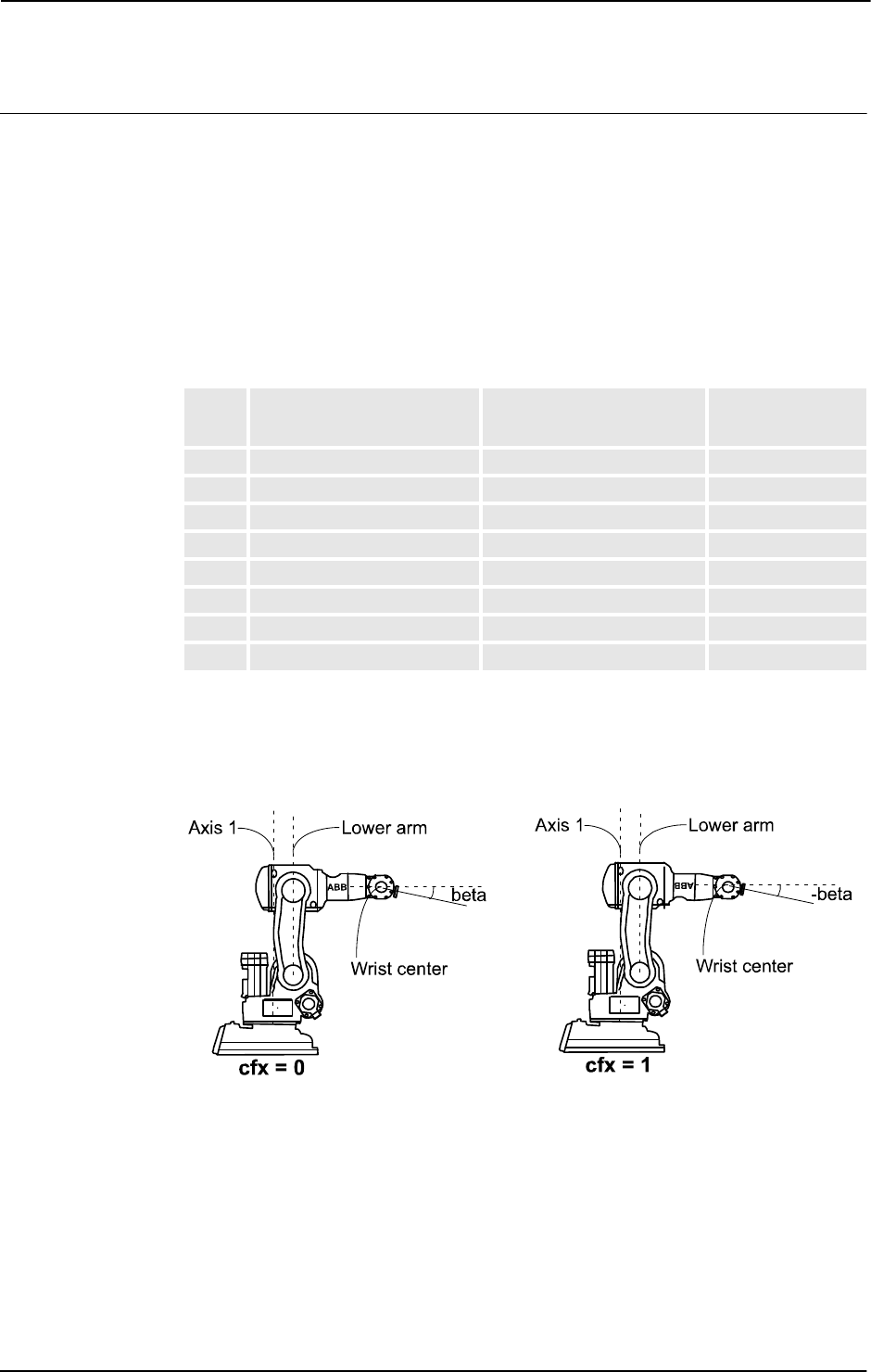
3 Data types
3.8. confdata - Robot configuration data
RobotWare - OS
3HAC 16581-1 Revision: J1094
© Copyright 2004-2010 ABB. All rights reserved.
Robot configuration data for IRB 140, 6600, 6650, 7600
There are three singularities within the robot’s working range (See RAPID reference manual
- RAPID summary, section Motion and I/O principles - Singularities).
• cf1 is the quadrant number for axis 1.
• cf4 is the quadrant number for axis 4.
• cf6 is the quadrant number for axis 6.
cfx is used to select one of eight possible robot configurations numbered from 0 through 7.
The table below describes each one of them in terms of how the robot is positioned relative
to the three singularities.
The pictures below give an example of how the same tool position and orientation is attained
by using the eight different configurations.
The following figure shows an example of robot configuration 0 and 1. Note the different
signs of the axis 5 angle.
xx0500002400
cfx
Wrist center relative to
axis 1
Wrist center relative to
lower arm
Axis 5 angle
0 In front of In front of Positive
1 In front of In front of Negative
2 In front of Behind Positive
3 In front of Behind Negative
4 Behind In front of Positive
5 Behind In front of Negative
6 Behind Behind Positive
7 Behind Behind Negative
Continued
Continues on next page
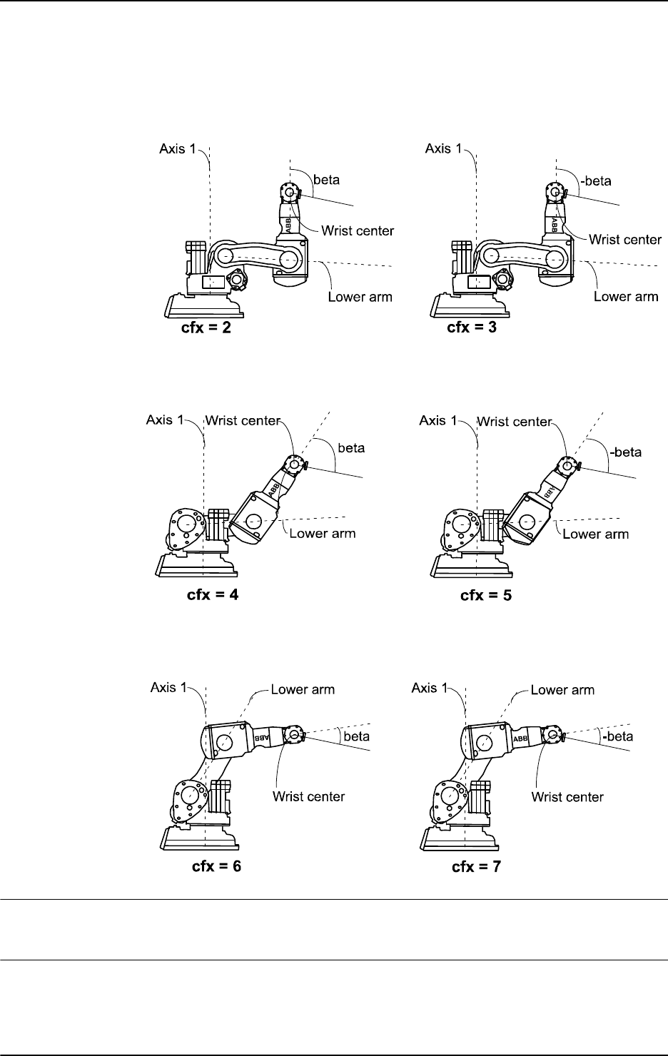
3 Data types
3.8. confdata - Robot configuration data
RobotWare - OS
10953HAC 16581-1 Revision: J
© Copyright 2004-2010 ABB. All rights reserved.
The following figure shows an example of robot configuration 2 and 3. Note the different
signs of the axis 5 angle.
xx0500002401
The following figure shows an example of robot configuration 4 and 5. Note the different
signs of the axis 5 angle.
xx0500002402
The following figure shows an example of robot configuration 6 and 7. Note the different
signs of the axis 5 angle.
xx0500002403
Robot configuration data for IRB 340
Only the configuration parameter
cf4 is used.
Robot configuration data for IRB 260, 660
Only the configuration parameter
cf6 is used.
Continued
Continues on next page

3 Data types
3.8. confdata - Robot configuration data
RobotWare - OS
3HAC 16581-1 Revision: J1096
© Copyright 2004-2010 ABB. All rights reserved.
Robot configuration data for IRB 1400, 2400, 3400, 4400, 6400
Only the three configuration parameters
cf1, cf4, and cf6 are used.
Robot configuration data for IRB 5400
All four configuration parameters are used.
cf1, cf4, cf6 for joints 1, 4, and 6 respectively
and
cfx for joint 5.
Robot configuration data for IRB 5404, 5406
The robots have two rotation axes (arms 1 and 2) and one linear axis (arm 3).
• cf1 is used for the rotating axis 1
• cfx is used for the rotating axis 2
• cf4 and cf6 are not used
Robot configuration data for IRB 5413, 5414, 5423
The robots have two linear axes (arms 1 and 2) and one or two rotating axes (arms 4 and 5).
(Arm 3 locked).
• cf1 is used for the linear axis 1
• cfx is used for the linear axis 2
• cf4 is used for the rotating axis 4
• cf6 is not used
Robot configuration data for IRB 840
The robot has three linear axes (arms 1, 2 and 3) and one rotating axis (arm 4).
• cf1 is used for the linear axis 1
• cfx is used for the linear axis 2
• cf4 is used for the rotating axis 4
• cf6 is not used
Because of the robot’s mainly linear structure, the correct setting of the configuration
parameters
c1, cx is of less importance.
Components
cf1
Data type: num
Rotating axis:
The current quadrant of axis 1, expressed as a positive or negative integer.
Linear axis:
The current meter interval of axis 1, expressed as a positive or negative integer.
Continued
Continues on next page

3 Data types
3.8. confdata - Robot configuration data
RobotWare - OS
10973HAC 16581-1 Revision: J
© Copyright 2004-2010 ABB. All rights reserved.
cf4
Data type: num
Rotating axis:
The current quadrant of axis 4, expressed as a positive or negative integer.
Linear axis:
The current meter interval of axis 4, expressed as a positive or negative integer.
cf6
Data type: num
Rotating axis:
The current quadrant of axis 6, expressed as a positive or negative integer.
Linear axis:
The current meter interval of axis 6, expressed as a positive or negative integer.
cfx
Data type: num
Rotating axis:
For the IRB 140, the current robot configuration, expressed as an integer in the range from 0
to 7.
For the IRB 5400, the current quadrant of axis 5, expressed as a positive or negative integer.
For other robots, using the current quadrant of axis 2, expressed as a positive or negative
integer.
Linear axis:
The current meter interval of axis 2, expressed as a positive or negative integer.
Basic examples
Basic examples of the data type
confdata are illustrated below.
Example 1
VAR confdata conf15 := [1, -1, 0, 0]
A robot configuration conf15 for robot type IRB 5400 is defined as follows:
• The axis configuration of the robot axis 1 is quadrant 1, i.e. 90-180º.
• The axis configuration of the robot axis 4 is quadrant -1, i.e. 0-(-90º).
• The axis configuration of the robot axis 6 is quadrant 0, i.e. 0 - 90º.
• The axis configuration of the robot axis 5 is quadrant 0, i.e. 0 - 90º.
Structure
< dataobject of confdata >
< cf1 of num >
< cf4 of num >
< cf6 of num >
< cfx of num >
Continued
Continues on next page

3 Data types
3.8. confdata - Robot configuration data
RobotWare - OS
3HAC 16581-1 Revision: J1098
© Copyright 2004-2010 ABB. All rights reserved.
Related information
For information about See
Coordinate systems Technical reference manual - RAPID overview,
section Motion and I/O principles - Coordinate
systems
Handling configuration data Technical reference manual - RAPID overview,
section Motion and I/O principles - Robot configura-
tion
Position data robtarget - Position data on page 1176
Continued

3 Data types
3.9. corrdescr - Correction generator descriptor
Path Offset
10993HAC 16581-1 Revision: J
© Copyright 2004-2010 ABB. All rights reserved.
3.9. corrdescr - Correction generator descriptor
Usage
corrdescr (Correction generator descriptor) is used by correction generators. A correction
generator adds geometric offsets in the path coordinate system.
Description
Data of the type
corrdescr contains a reference to a correction generator.
Connection to a correction generator is done by the instruction
CorrCon and the descriptor
(the reference to the correction generator) can be used to deliver geometric offsets in the path
coordinate system with the instruction
CorrWrite.
Offsets provided earlier can be removed by disconnecting a correction generator with the
instruction
CorrDiscon. All connected correction generators can be removed with the
instruction
CorrClear.
The function
CorrRead returns the sum of all the delivered offsets so far (includes all
connected correction generators).
Basic examples
Basic examples of the data type
corrdescr are illustrated below.
Example 1
VAR corrdescr id;
VAR pos offset;
...
CorrCon id;
offset := [1, 2 ,3];
CorrWrite id, offset;
A correction generator is connected with the instruction CorrCon and referenced by the
descriptor
id. Offsets are then delivered to the correction generator (with reference id) using
the instruction
CorrWrite.
Characteristics
corrdescr is a non-value data type.
Continues on next page

3 Data types
3.9. corrdescr - Correction generator descriptor
Path Offset
3HAC 16581-1 Revision: J1100
© Copyright 2004-2010 ABB. All rights reserved.
Related information
For information about See
Connects to a correction generator CorrCon - Connects to a correction generator on
page 71
Disconnects from a correction generator CorrDiscon - Disconnects from a correction
generator on page 76
Writes to a correction generator CorrWrite - Writes to a correction generator on
page 77
Reads the current total offsets CorrRead - Reads the current total offsets on
page 803
Removes all correction generators CorrClear - Removes all correction generators
on page 70
Characteristics of non-value data types Technical reference manual - RAPID overview,
section Basic characteristics - Data types
Continued

3 Data types
3.10. datapos - Enclosing block for a data object
RobotWare - OS
11013HAC 16581-1 Revision: J
© Copyright 2004-2010 ABB. All rights reserved.
3.10. datapos - Enclosing block for a data object
Usage
datapos is the enclosing block to a data object (internal system data) retrieved with the
function
GetNextSym.
Description
Data of the type
datapos contains information of where a certain object is defined in the
system. It is used for instructions
GetDataVal and SetDataVal.
Basic examples
Basic examples of the data type
datapos are illustrated below.
Example 1
VAR datapos block;
VAR string name;
VAR bool truevar:=TRUE;
...
SetDataSearch "bool" \Object:="my.*" \InMod:="mymod"\LocalSym;
WHILE GetNextSym(name,block) DO
SetDataVal name\Block:=block,truevar;
ENDWHILE
This session will set all local bool data objects that begin with my in the module mymod to
TRUE.
Characteristics
datapos is a non-value data type.
Related information
For information about See
Define a symbol set in a search session SetDataSearch - Define the symbol set in a
search sequence on page 433
Get next matching symbol GetNextSym - Get next matching symbol on
page 855
Get the value of a data object GetDataVal - Get the value of a data object on
page 110
Set the value of a data object SetDataVal - Set the value of a data object on
page 437
Set the value of many object SetAllDataVal - Set a value to all data objects in
a defined set on page 429

3 Data types
3.11. dionum - Digital values (0 - 1)
RobotWare - OS
3HAC 16581-1 Revision: J1102
© Copyright 2004-2010 ABB. All rights reserved.
3.11. dionum - Digital values (0 - 1)
Usage
dionum (digital input output numeric) is used for digital values (0 or 1).
This data type is used in conjunction with instructions and functions that handle digital input
or output signals.
Description
Data of the type
dionum represents a digital value 0 or 1.
Basic examples
Basic examples of the data type
dionum are illustrated below.
Example 1
CONST dionum close := 1;
SetDO grip1, close;
Definition of a constant close with a value equal to 1. The signal grip1 is then set to
close, i.e. 1.
Predefined data
The constants
high, low, and edge are predefined in the system module base.sys:
CONST dionum low:=0;
CONST dionum high:=1;
CONST dionum edge:=2;
The constants low and high are designed for IO instructions.
Edge can be used together with the interrupt instructions ISignalDI and ISignalDO.
Characteristics
dionum is an alias data type for num and consequently inherits its characteristics.
Related information
For information about See
Summary input/output instructions Technical reference manual - RAPID overview,
section RAPID Summary - Input and output signals
Configuration of I/O Technical reference manual - System parameters
Alias data types Technical reference manual - RAPID overview,
section Basic Characteristics- Data types

3 Data types
3.12. dir - File directory structure
RobotWare - OS
11033HAC 16581-1 Revision: J
© Copyright 2004-2010 ABB. All rights reserved.
3.12. dir - File directory structure
Usage
dir (directory) is used to traverse directory structures.
Description
Data of the type
dir contains a reference to a directory on disk or network. It can be linked
to the physical directory by means of the instruction
OpenDir and then used for reading.
Basic examples
Basic examples of the data type
dir are illustrated below.
Example 1
PROC lsdir(string dirname)
VAR dir directory;
VAR string filename;
OpenDir directory, dirname;
WHILE ReadDir(directory, filename) DO
TPWrite filename;
ENDWHILE
CloseDir directory;
ENDPROC
This example prints out the names of all files or subdirectories under the specified directory.
Characteristics
dir is a non-value data type and cannot be used in value-oriented operations.
Related information
For information about See
Open a directory OpenDir - Open a directory on page 285
Make a directory MakeDir - Create a new directory on page 218
Read a directory ReadDir - Read next entry in a directory on page 944
Close a directory CloseDir - Close a directory on page 56
Remove a directory RemoveDir - Delete a directory on page 355
Remove a file RemoveFile - Delete a file on page 356
Rename a file RenameFile - Rename a file on page 357
Check file type IsFile - Check the type of a file on page 878

3 Data types
3.13. dnum - Double numeric values
RobotWare - OS
3HAC 16581-1 Revision: J1104
© Copyright 2004-2010 ABB. All rights reserved.
3.13. dnum - Double numeric values
Usage
dnum is used for numeric values, for example counters. It can handle larger integer values
than data type
num but its characteristics and function is the same as for num.
Description
The value of the
dnum data type can be:
• An integer, for example -5
• A decimal number, for example 3.45
It can also be written exponentially, for example 2E3 (= 2*10^3 = 2000), 2.5E-2 (= 0.025).
Integers between -4503599627370496 and +4503599627370496 are always stored as exact
integers.
Basic examples
Basic examples of the data type
dnum are illustrated below.
Example 1
VAR dnum reg1;
...
reg1:=1000000;
reg1
is assigned the value 1000000.
Example 2
VAR dnum hex;
Var dnum bin;
VAR dnum oct;
! Hexadecimal representation of decimal value 4294967295
hex := 0xFFFFFFFF;
! Binary representation of decimal value 255
bin := 0b11111111;
! Octal representation of decimal value 255
oct := 0o377;
Example 3
VAR dnum a:=0;
VAR dnum b:=0;
a := 10 DIV 3;
b := 10 MOD 3;
Integer division where a is assigned an integer (=3) and b is assigned the remainder (=1).
Limitations
Literal values between -4503599627370496 to 4503599627370496 assigned to a
dnum
variable are stored as exact integers.
If a literal value that has been interpreted as a
num is assigned/used as a dnum, it is
automatically converted to a
dnum.
Continues on next page

3 Data types
3.13. dnum - Double numeric values
RobotWare - OS
11053HAC 16581-1 Revision: J
© Copyright 2004-2010 ABB. All rights reserved.
Related information
For information about See
Numeric values using data type num num - Numeric values on page 1146
Numeric expressions Technical reference manual - RAPID
overview, section Basic RAPID programming
Operations using numeric values Technical reference manual - RAPID
overview, section Basic RAPID programming
Continued

3 Data types
3.14. errdomain - Error domain
RobotWare - OS
3HAC 16581-1 Revision: J1106
© Copyright 2004-2010 ABB. All rights reserved.
3.14. errdomain - Error domain
Usage
errdomain (error domain) is used to specify an error domain.
Description
Data of the type
errdomain represents the domain where the error, warning, or state changed
is logged.
Basic examples
Basic examples of the data type
errdomain are illustrated below.
Example 1
VAR errdomain err_domain;
VAR num err_number;
VAR errtype err_type;
VAR trapdata err_data;
...
TRAP trap_err
GetTrapData err_data;
ReadErrData err_data, err_domain, err_number, err_type;
ENDTRAP
When an error is trapped to the trap routine trap_err, the error domain, the error number,
and the error type are saved into appropriate variables.
Predefined data
The following predefined constants can be used to specify an error domain.
Characteristics
errdomain is an alias data type for num and consequently inherits its characteristics.
Name Error Domain Value
COMMON_ERR All error and state changed domains 0
OP_STATE Operational state change 1
SYSTEM_ERR System errors 2
HARDWARE_ERR Hardware errors 3
PROGRAM_ERR Program errors 4
MOTION_ERR Motion errors 5
OPERATOR_ERR Operator errors - Obsolete, not used anymore 6
IO_COM_ERR I/O and Communication errors 7
USER_DEF_ERR User defined errors (raised by RAPID) 8
OPTION_PROD_ERR Optional product errors - Obsolete, not used any
more
9
PROCESS_ERR Process errors 11
CFG_ERR Configuration error 12
Continues on next page

3 Data types
3.14. errdomain - Error domain
RobotWare - OS
11073HAC 16581-1 Revision: J
© Copyright 2004-2010 ABB. All rights reserved.
Related information
For information about See
Ordering an interrupt on errors IError - Orders an interrupt on errors on page 126
Error numbers Operating manual - Trouble shooting
Alias data types Technical reference manual - RAPID overview, section
Basic characteristics - Data types
Continued

3 Data types
3.15. errnum - Error number
RobotWare - OS
3HAC 16581-1 Revision: J1108
© Copyright 2004-2010 ABB. All rights reserved.
3.15. errnum - Error number
Usage
errnum is used to describe all recoverable (non fatal) errors that occur during program
execution, such as division by zero.
Description
If the robot detects an error during program execution, this can be dealt with in the error
handler of the routine. Examples of such errors are values that are too high and division by
zero. The system variable
ERRNO, of type errnum, is thus assigned different values
depending on the nature of an error. The error handler may be able to correct an error by
reading this variable and then program execution can continue in the correct way.
An error can also be created from within the program using the
RAISE instruction. This
particular type of error can be detected in the error handler by specifying an error number
(within the range 1-90 or booked with instruction
BookErrNo) as an argument to RAISE.
Basic examples
Basic examples of the data type
errnum are illustrated below.
Example 1
reg1 := reg2 / reg3;
...
ERROR
IF ERRNO = ERR_DIVZERO THEN
reg3 := 1;
RETRY;
ENDIF
If reg3 = 0, the robot detects an error when division is taking place. This error, however,
can be detected and corrected by assigning
reg3 the value 1. Following this, the division can
be performed again and program execution can continue.
Example 2
CONST errnum machine_error := 1;
...
IF di1=0 RAISE machine_error;
...
ERROR
IF ERRNO=machine_error RAISE;
An error occurs in a machine (detected by means of the input signal di1). A jump is made to
the error handler in the routine which, in turn, calls the error handler of the calling routine
where the error may possibly be corrected. The constant,
machine_error, is used to let the
error handler know exactly what type of error has occurred.
Continues on next page

3 Data types
3.15. errnum - Error number
RobotWare - OS
11093HAC 16581-1 Revision: J
© Copyright 2004-2010 ABB. All rights reserved.
Predefined data
The system variable
ERRNO can be used to read the latest error that occurred. A number of
predefined constants can be used to determine the type of error that has occurred.
Name Cause of error
ERR_ACC_TOO_LOW Too low acceleration/deceleration specified in
instruction PathAccLim or WorldAccLim
ERR_ALIASIO_DEF The FromSignal is not defined in the IO configuration
or the ToSignal is not declared in the RAPID program
or is defined in the IO configuration. Instruction
AliasIO
ERR_ALIASIO_TYPE The signal types for the arguments FromSignal and
ToSignal is not the same (signalx). Instruction
AliasIO.
ERR_ALRDYCNT The interrupt variable is already connected to a TRAP
routine
ERR_ALRDY_MOVING The robot is already moving when executing a
StartMove or StartMoveRetry instruction
ERR_AO_LIM Analog signal value outside limit
ERR_ARGDUPCND More than one present conditional argument for the
same parameter
ERR_ARGNAME Argument is an expression, not present, or of type
switch when executing ArgName
ERR_ARGNOTPER Argument is not a persistent reference
ERR_ARGNOTVAR Argument is not a variable reference
ERR_ARGVALERR Argument value error
ERR_AXIS_ACT Axis is not active
ERR_AXIS_IND Axis is not independent
ERR_AXIS_MOVING Axis is moving
ERR_AXIS_PAR Parameter axis in instruction is wrong
ERR_BUSSTATE An IOEnable is done, and the bus is in error state or
enter error state before the unit is activated
ERR_BWDLIMIT Limit StepBwdPath
ERR_CALC_NEG StrDig necative calculation error
ERR_CALC_OVERFLOW StrDig calculation overflow
ERR_CALC_DIVZERO StrDig division by zero
ERR_CALLPROC Procedure call error (not procedure) at runtime (late
binding)
ERR_CFG_INTERNAL Not allowed to read internal parameter - ReadCfgData
ERR_CFG_ILLTYPE Type mismatch - ReadCfgData, WriteCfgData
ERR_CFG_LIMIT Data limit - WriteCfgData
ERR_CFG_NOTFND Not found - ReadCfgData, WriteCfgData
ERR_CFG_OUTOFBOUNDS If ListNo is -1 at input or bigger then number of available
instances - ReadCfgData, WriteCfgData
ERR_CNTNOTVAR CONNECT target is not a variable reference
ERR_CNV_NOT_ACT The conveyor is not activated
ERR_CNV_CONNECT The WaitWobj instruction is already active
Continued
Continues on next page

3 Data types
3.15. errnum - Error number
RobotWare - OS
3HAC 16581-1 Revision: J1110
© Copyright 2004-2010 ABB. All rights reserved.
ERR_CNV_DROPPED The object that the instruction WaitWobj was waiting
for has been dropped.
ERR_COMM_EXT Communication error with the external system.
ERR_COMM_INIT_FAILED Communication interface could not be initialized.
ERR_DATA_RECV The data received from remote system is incorrect.
ERR_DEV_MAXTIME Timeout when executing a ReadBin, ReadNum, or a
ReadStr instruction
ERR_DIPLAG_LIM Too big DipLag in the instruction TriggSpeed
connected to current TriggL/TriggC/TriggJ
ERR_DIVZERO Division by zero
ERR_EXECPHR An attempt was made to execute an instruction using a
place holder
ERR_FILEACC A file is accessed incorrectly
ERR_FILEEXIST A file already exists
ERR_FILEOPEN A file cannot be opened
ERR_FILNOTFND File not found
ERR_FNCNORET No return value
ERR_FRAME Unable to calculate new frame
ERR_GO_LIM Digital group signal value outside limit
ERR_ILLDIM Incorrect array dimension
ERR_ILLQUAT Attempt to use illegal orientation (quaternion) valve
ERR_ILLRAISE Error number in RAISE out of range
ERR_INDCNV_ORDER An instruction requires execution of IndCnvInit
before it is executed.
ERR_INOISSAFE If trying to deactivate a safe interrupt temporarily with
ISleep.
ERR_INOMAX No more interrupt numbers available
ERR_INT_NOTVAL Not valid integer, decimal value
ERR_INT_MAXVAL Not valid integer, too large or small value
ERR_INVDIM Dimensions are not equal
ERR_IODISABLE Timeout when executing IODisable
ERR_IOENABLE Timeout when executing IOEnable
ERR_IOERROR I/O Error from instruction Save
ERR_LINKREF Reference error in the program task
ERR_LOADED The program module is already loaded
ERR_LOADID_FATAL Only internal use in LoadId
ERR_LOADID_RETRY Only internal use in LoadId
ERR_LOADNO_INUSE The load session is in use in StartLoad
ERR_LOADNO_NOUSE The load session is not in use in CancelLoad
ERR_MAXINTVAL The integer value is too large
ERR_MODULE Incorrect module name in instruction Save and
EraseModule
ERR_MOD_NOTLOADED Module not loaded or installed from ModTime
ERR_NAME_INVALID If the unit name does not exist or if the unit is not
allowed to be disabled
Name Cause of error
Continued
Continues on next page

3 Data types
3.15. errnum - Error number
RobotWare - OS
11113HAC 16581-1 Revision: J
© Copyright 2004-2010 ABB. All rights reserved.
ERR_NORUNUNIT If there is no contact with the unit
ERR_NOTARR Data is not an array
ERR_NOTEQDIM The array dimension used when calling the routine
does not coincide with its parameters
ERR_NOTINTVAL Not an integer value
ERR_NOTPRES A parameter is used, despite the fact that the corre-
sponding argument was not used at the routine call
ERR_NOTSAVED Module has been changed since it was loaded into the
system
ERR_NOT_MOVETASK Specify task is a non-motion task
ERR_NUM_LIMIT Value is not an integer and/or not in the range of -
8388607 to +8388608
ERR_OUTOFBND The array index is outside the permitted limits
ERR_OVERFLOW Clock overflow
ERR_PATH Missing destination path in instruction Save
ERR_PATHDIST Too long regain distance for StartMove or
StartMoveRetry instruction
ERR_PATH_STOP Stop of the movement because of some process error
ERR_PID_MOVESTOP Only internal use in LoadId
ERR_PID_RAISE_PP Error from ParIdRobValid or ParIdPosValid
ERR_PRGMEMFULL Program memory full
ERR_PROCSIGNAL_OFF Process signal is off
ERR_PROGSTOP The robot is in program stop state when executing a
StartMove or StartMoveRetry instruction
ERR_RANYBIN_CHK Check sum error detected at data transfer with
instruction ReadAnyBin
ERR_RANYBIN_EOF End of file is detected before all bytes are read in
instruction ReadAnyBin
ERR_RCVDATA An attempt was made to read non-numeric data with
ReadNum
ERR_REFUNKDAT Reference to entire unknown data object
ERR_REFUNKFUN Reference to unknown function
ERR_REFUNKPRC Reference to unknown procedure at linking time or at
run time (late binding)
ERR_REFUNKTRP Reference to unknown trap
ERR_RMQ_DIM Wrong dimensions, the dimensions of the given data
are not equal to the dimensions of the data in the
message.
ERR_RMQ_FULL Destination message queue is full.
ERR_RMQ_INVALID Destination slot lost or invalid
ERR_RMQ_INVMSG Invalid message, likely sent from other client then a
RAPID task.
ERR_RMQ_MSGSIZE Size of message is too big. Decrease message size.
ERR_RMQ_NAME The given slot name is not valid or not found.
ERR_RMQ_NOMSG No message in queue, likely the results of power fail.
Name Cause of error
Continued
Continues on next page

3 Data types
3.15. errnum - Error number
RobotWare - OS
3HAC 16581-1 Revision: J1112
© Copyright 2004-2010 ABB. All rights reserved.
ERR_RMQ_TIMEOUT Timeout occurred while waiting for answer in
RMQSendWait.
ERR_RMQ_VALUE The value syntax does not match the data type.
ERR_ROBLIMIT Axis outside working area or limits exceeded for at least
one coupled joint
ERR_SC_WRITE Error when sending to external computer
ERR_SIGSUPSEARCH The signal has already a positive value at the beginning
of the search process
ERR_STARTMOVE The robot is in hold state when executing a StartMove
or StartMoveRetry instruction
ERR_ADDR_INUSE The address and port is already in use and can not be
used again. Use a different port number or address in
SocketBind.
ERR_SOCK_CLOSED The socket is closed, or is not created
ERR_SOCK_TIMEOUT The connection was not established within the time-out
time
ERR_SPEED_REFRESH_LIM Override out of limit in SpeedRefresh
ERR_STRTOOLNG The string is too long
ERR_SYM_ACCESS Symbol read/write access error
ERR_SYNCMOVEOFF Timeout from SyncMoveOff
ERR_SYNCMOVEON Timeout from SyncMoveOn
ERR_SYNTAX Syntax error in the loaded module
ERR_TASKNAME Task name not found in the system
ERR_TP_DIBREAK A read instruction from FlexPendant was interrupted by
a digital input
ERR_TP_DOBREAK A read instruction from FlexPendant was interrupted by
a digital output
ERR_TP_MAXTIME Timeout when executing a read instruction from
FlexPendant
ERR_TP_NO_CLIENT No client to interact with when using a read instruction
from FlexPendant
ERR_TRUSTLEVEL Not allowed to disable I/O unit
ERR_TXTNOEXIST Wrong table or index in function TextGet
ERR_UI_INITVALUE Initial value error in function UINumEntry
ERR_UI_MAXMIN Min value is greater then max value in function
UINumEntry
ERR_UI_NOTINT Value is not an integer when specified that an integer
should be used when using UINumEntry
ERR_UISHOW_FATAL Other error then ERR_UISHOW_FATAL in instruction
UIShow
ERR_UISHOW_FULL No space left on FlexPendant for another application
when using instruction UIShow
ERR_UNIT_PAR Parameter Mech_unit in TestSignDefine is wrong
ERR_UNKINO Unknown interrupt number
ERR_UNKPROC Incorrect reference to the load session in instruction
WaitLoad
ERR_UNLOAD Unload error in instruction UnLoad or WaitLoad
Name Cause of error
Continued
Continues on next page

3 Data types
3.15. errnum - Error number
RobotWare - OS
11133HAC 16581-1 Revision: J
© Copyright 2004-2010 ABB. All rights reserved.
Characteristics
errnum is an alias data type for num and consequently inherits its characteristics.
Related information
ERR_WAITSYNCTASK Time-out from WaitSyncTask
ERR_WAIT_MAXTIME Time-out when executing a WaitDI or WaitUntil
instruction
ERR_WHLSEARCH No search stop
ERR_WOBJ_MOVING The mechanical unit with work object is moving
CalcJointT
Name Cause of error
For information about See
Error recovery Technical reference manual - RAPID overview
Data types in general, alias data types Technical reference manual - RAPID overview
Continued

3 Data types
3.16. errstr - Error string
RobotWare - OS
3HAC 16581-1 Revision: J1114
© Copyright 2004-2010 ABB. All rights reserved.
3.16. errstr - Error string
Usage
errstr is used to write text in error messages.
Basic examples
Basic examples of the data type
errstr are illustrated below.
Example 1
VAR errstr arg:= "This is an example";
ErrLog 5100, \W, ERRSTR_TASK, ERRSTR_CONTEXT, arg, ERRSTR_EMPTY,
ERRSTR_UNUSED;
Predefined data
Characteristics
errstr is an alias data type for string and consequently inherits its characteristics.
Related information
Name Description
ERRSTR_EMPTY Argument is empty
ERRSTR_UNUSED Argument is not used
ERRSTR_TASK Name of current task
ERRSTR_CONTEXT Context
For information about See
Data types in general, alias data types Technical reference manual - RAPID overview,
section Basic characteristics - Data Types

3 Data types
3.17. errtype - Error type
RobotWare - OS
11153HAC 16581-1 Revision: J
© Copyright 2004-2010 ABB. All rights reserved.
3.17. errtype - Error type
Usage
errtype (error type) is used to specify an error type.
Description
Data of the type
errtype represents the type (state change, warning, error) of an error
message.
Basic examples
Basic examples of the data type
errtype are illustrated below.
Example 1
VAR errdomain err_domain;
VAR num err_number;
VAR errtype err_type;
VAR trapdata err_data;
...
TRAP trap_err
GetTrapData err_data;
ReadErrData err_data, err_domain, err_number, err_type;
ENDTRAP
When an error is trapped to the trap routine trap_err, the error domain, the error number,
and the error type are saved into appropriate variables.
Predefined data
The following predefined constants can be used to specify an error type.
Characteristics
errtype is an alias data type for num and consequently inherits its characteristics.
Related information
Name Error Type Value
TYPE_ALL Any type of error (state change, warning, error) 0
TYPE_STATE State change (operational message) 1
TYPE_WARN Warning (such as RAPID recoverable error) 2
TYPE_ERR Error 3
For information about See
Ordering an interrupt on errors IError - Orders an interrupt on errors on page 126
Error numbers Operating manual - Trouble shooting
Alias data types Technical reference manual - RAPID overview,
section Basic characteristics - Data types

3 Data types
3.18. event_type - Event routine type
RobotWare - OS
3HAC 16581-1 Revision: J1116
© Copyright 2004-2010 ABB. All rights reserved.
3.18. event_type - Event routine type
Usage
event_type is used to represent the actual event routine type with a symbolic constant.
Description
With the function
EventType, it is possible to check if the actual RAPID code is executed
because of some specific system event or not.
Basic examples
Basic example of the data type
event_type is illustrated below.
Example 1
VAR event_type my_type;
...
my_type := EventType( );
The event routine type that is executed will be stored in the variable my_type.
Predefined data
Following constants of type
event_type are predefined:
Characteristics
event_type is an alias data type for num and consequently inherits its characteristics.
Related information
RAPID constant Value Type of event executed
EVENT_NONE 0 No event is executed
EVENT_POWERON 1 POWER_ON event
EVENT_START 2 START event
EVENT_STOP 3 STOP event
EVENT_QSTOP 4 QSTOP event
EVENT_RESTART 5 RESTART event
EVENT_RESET 6 RESET event
EVENT_STEP 7 STEP event
For information about See
Event routines in general Technical reference manual - System
parameters, section Controller - Event Routine
Get event type EventType - Get current event type inside any
event routine on page 837
Data types in general, alias data types Technical reference manual - RAPID overview,
section Basic characteristics - Data types

3 Data types
3.19. exec_level - Execution level
RobotWare - OS
11173HAC 16581-1 Revision: J
© Copyright 2004-2010 ABB. All rights reserved.
3.19. exec_level - Execution level
Usage
exec_level is used to specify program execution level.
Description
With the function
ExecLevel, it is possible to get the actual execution level for the RAPID
code that currently is executed.
Predefined data
The following constants of type
exec_level are predefined:
1) With
LEVEL_SERVICE means event routine, service routine (including Call Routine) and
interrupt routine from system input signal.
Characteristics
exec_level is an alias data type for num and consequently inherits its characteristics.
Related information
RAPID constant Value Execution level
LEVEL_NORMAL 0 Execute on base level
LEVEL_TRAP 1 Execute in TRAP routine
LEVEL_SERVICE 2 Execute in service routine 1)
For information about See
Get current execution level ExecLevel - Get execution level on page 840

3 Data types
3.20. extjoint - Position of external joints
RobotWare - OS
3HAC 16581-1 Revision: J1118
© Copyright 2004-2010 ABB. All rights reserved.
3.20. extjoint - Position of external joints
Usage
extjoint is used to define the axis positions of external axes, positioners or workpiece
manipulators.
Description
The robot can control up to six external axes in addition to its six internal axes, i.e. a total of
twelve axes. The six external axes are logically denoted: a, b, c, d, e, f. Each such logical axes
can be connected to a physical axis and, in this case, the connection is defined in the system
parameters.
Data of the type
extjoint is used to hold position values for each of the logical axes a - f.
For each logical axis connected to a physical axis, the position is defined as follows:
• For rotating axes– the position is defined as the rotation in degrees from the calibration
position.
• For linear axes – the position is defined as the distance in mm from the calibration
position.
If a logical axis is not connected to a physical one then the value 9E9 is used as a position
value, indicating that the axis is not connected. At the time of execution, the position data of
each axis is checked and it is checked whether or not the corresponding axis is connected. If
the stored position value does not comply with the actual axis connection, the following
applies:
• If the position is not defined in the position data (value is 9E9) then the value will be
ignored if the axis is connected and not activated. But if the axis is activated, it will
result in an error.
• If the position is defined in the position data, although the axis is not connected, then
the value will be ignored.
No movement is performed but no error is generated for an axis with valid position data if the
axis is not activated.
If an external axis offset is used (instruction
EOffsOn or EOffsSet) then the positions are
specified in the
ExtOffs coordinate system.
If some external axis is running in independent mode and some new movement shall be
performed by the robot and it’s external axes then the position data for the external axis in
independent mode must not be 9E9 but some arbitrary value (not used but the system).
Continues on next page

3 Data types
3.20. extjoint - Position of external joints
RobotWare - OS
11193HAC 16581-1 Revision: J
© Copyright 2004-2010 ABB. All rights reserved.
Components
eax_a
external axis a
Data type:
num
The position of the external logical axis“ a” expressed in degrees or mm (depending on the
type of axis).
...
eax_f
external axis f
Data type:
num
The position of the external logical axis“ f” expressed in degrees or mm (depending on the
type of axis).
Basic examples
Basic examples of the data type
extjoint are illustrated below.
Example 1
VAR extjoint axpos10 := [ 11, 12.3, 9E9, 9E9, 9E9, 9E9] ;
The position of an external positioner, axpos10, is defined as follows:
• The position of the external logical axis “a” is set to 11, expressed in degrees or mm
(depending on the type of axis).
• The position of the external logical axis“ b” is set to 12.3, expressed in degrees or mm
(depending on the type of axis).
• Axes c to f are undefined.
Structure
< dataobject of extjoint >
< eax_a of num >
< eax_b of num >
< eax_c of num >
< eax_d of num >
< eax_e of num >
< eax_f of num >
Related information
For information about See
Position data robtarget - Position data on page 1176
jointtarget - Joint position data on page 1129
ExtOffs coordinate system EOffsOn - Activates an offset for external axes on
page 88
Continued

3 Data types
3.21. handler_type - Type of execution handler
RobotWare - OS
3HAC 16581-1 Revision: J1120
© Copyright 2004-2010 ABB. All rights reserved.
3.21. handler_type - Type of execution handler
Usage
handler_type is used to specify type of execution handler in RAPID program routine.
Description
With the function
ExecHandler, it is possible to check if the actual RAPID code is executed
in some execution handler in
RAPID program routine.
Basic examples
Basic example of the data type
handler_type is illustrated below.
Example 1
VAR handler_type my_type;
...
my_type := ExecHandler( );
The type of execution handler that the code is executed in, will be stored in the variable
my_type.
Predefined data
Following constants of type
handler_type are predefined:
Characteristics
handler_type is an alias data type for num and consequently inherits its characteristics.
Related information
RAPID constant Value Type of execution handler
HANDLER_NONE 0 Not executed in any handler
HANDLER_BWD 1 Executed in BACKWARD handler
HANDLER_ERR 2 Executed in ERROR handler
HANDLER_UNDO 3 Executed in UNDO handler
For information about See
Get type of execution handler ExecHandler - Get type of execution handler
on page 839

3 Data types
3.22. icondata - Icon display data
RobotWare - OS
11213HAC 16581-1 Revision: J
© Copyright 2004-2010 ABB. All rights reserved.
3.22. icondata - Icon display data
Usage
icondata is used for representing standard icons on the User Device such as the
FlexPendant.
Description
An
icondata enumeration constant may be passed to the Icon argument in the instruction
UIMsgBox and functions UIMessageBox, UINumEntry, UINumTune, UIAlphaEntry, and
UIListView.
Basic examples
Basic examples of the data type
icondata are illustrated below.
Example 1
VAR btnres answer;
UIMsgBox "More ?" \Buttons:=btnYesNo \Icon:=iconInfo \Result:=
answer;
IF answer= resYes THEN
...
ELSEIF answer =ResNo THEN
...
ENDIF
The standard button enumeration constant iconInfo will give an information icon at the
head of the message box on the user interface.
Predefined data
The following constants of the data type
icondata are predefined in the system:
Characteristics
icondata is an alias data type for num and consequently inherits its characteristics.
Value Constant Icon
0 iconNone No icon
1 iconInfo Information icon
2 iconWarning Warning icon
3 iconError Error icon
Continues on next page

3 Data types
3.22. icondata - Icon display data
RobotWare - OS
3HAC 16581-1 Revision: J1122
© Copyright 2004-2010 ABB. All rights reserved.
Related information
For information about See
User Interaction Message Box UIMsgBox - User Message Dialog Box type
basic on page 644
User Interaction Message Box UIMessageBox - User Message Box type
advanced on page 1057
User Interaction Number Entry UINumEntry - User Number Entry on page 1064
User Interaction Number Tune UINumTune - User Number Tune on page 1070
User Interaction Alpha Entry UIAlphaEntry - User Alpha Entry on page 1032
User Interaction List View UIListView - User List View on page 1050
Data types in general, alias data types Technical reference manual - RAPID overview,
section Basic Characteristics - Data Types
Continued

3 Data types
3.23. identno - Identity for move instructions
MultiMove - Coordinated Robots
11233HAC 16581-1 Revision: J
© Copyright 2004-2010 ABB. All rights reserved.
3.23. identno - Identity for move instructions
Usage
identno (Identity Number) is used to control synchronizing of two or more coordinated
synchronized movements with each other.
The data type
identno can only be used in a MultiMove system with option Coordinated
Robots and only in program tasks defined as Motion Task.
Description
Move instructions in a MultiMove system must be programmed with parameter
\ID of data
type
identno, if coordinated synchronized movement, and \ID is not allowed in any other
cases.
The specified
\ID number must be the same in all cooperating program tasks. The id number
gives a guarantee that the movements are not mixed up at runtime.
In coordinated synchronized mode, there must be the same amount of executed move
instructions in all program tasks. The optional parameter
\ID of data type identno will be
used to check that associated move instructions are run in parallel before the start of the
movements. The
\ID number must be the same in the move instructions that are run in
parallel.
The user does not have to declare any variable of type
identno, but can use a number
directly in the instructions (see Basic examples).
Basic examples
Basic examples of the data type
identno are illustrated below.
Example 1
PERS tasks task_list{2} := [["T_ROB1"],["T_ROB2"]];
VAR syncident sync1;
VAR syncident sync2;
PROC proc1()
...
SyncMoveOn sync1, task_list;
MoveL *\ID:=10,v100,z50,mytool;
MoveL *\ID:=20,v100,fine,mytool;
SyncMoveOff sync2;
...
ENDPROC
Characteristics
identno is an alias data type for num and thus inherits its properties.
Continues on next page

3 Data types
3.23. identno - Identity for move instructions
MultiMove - Coordinated Robots
3HAC 16581-1 Revision: J1124
© Copyright 2004-2010 ABB. All rights reserved.
Related information
For information about See
Alias data types Technical reference manual - RAPID
overview, section Basic Characteristics - Data
types
Start coordinated synchronized movements SyncMoveOn - Start coordinated synchro-
nized movements on page 534
End coordinated synchronized movements SyncMoveOff - End coordinated synchronized
movements on page 528
Continued

3 Data types
3.24. intnum - Interrupt identity
RobotWare - OS
11253HAC 16581-1 Revision: J
© Copyright 2004-2010 ABB. All rights reserved.
3.24. intnum - Interrupt identity
Usage
intnum (interrupt numeric) is used to identify an interrupt.
Description
When a variable of type
intnum is connected to a trap routine, it is given a specific value
identifying the interrupt. This variable is then used in all dealings with the interrupt, such as
when ordering or disabling an interrupt.
More than one interrupt identity can be connected to the same trap routine. The system
variable
INTNO can thus be used in a trap routine to determine the type of interrupt that
occurs.
Basic examples
Basic examples of the data type
intnum are illustrated below.
Example 1
VAR intnum feeder_error;
...
CONNECT feeder_error WITH correct_feeder;
ISignalDI di1, 1, feeder_error;
An interrupt is generated when the input di1 is set to 1. When this happens, a call is made to
the correct_feeder trap routine.
Example 2
VAR intnum feeder1_error;
VAR intnum feeder2_error;
...
PROC init_interrupt();
...
CONNECT feeder1_error WITH correct_feeder;
ISignalDI di1, 1, feeder1_error;
CONNECT feeder2_error WITH correct_feeder;
ISignalDI di2, 1, feeder2_error;
...
ENDPROC
...
TRAP correct_feeder
IF INTNO=feeder1_error THEN
...
ELSE
...
ENDIF
...
ENDTRAP
An interrupt is generated when either of the inputs di1 or di2 is set to 1. A call is then made
to the
correct_feeder trap routine. The system variable INTNO is used in the trap routine
to find out which type of interrupt has occurred.
Continues on next page

3 Data types
3.24. intnum - Interrupt identity
RobotWare - OS
3HAC 16581-1 Revision: J1126
© Copyright 2004-2010 ABB. All rights reserved.
Limitations
The maximum number of active variables of type
intnum at any one time (between CONNECT
and
IDelete) is limited to 70.The maximum number of interrupts, in the queue for execution
of
TRAP routine at any one time, is limited to 30.
Characteristics
Intnum is an alias data type for num and thus inherits its properties.
Related information
For information about See
Summary of interrupts Technical reference manual - RAPID overview,
section RAPID Summary - Interrupts
Alias data types Technical reference manual - RAPID overview,
section Basic Characteristics - Data Types
Connecting interrupts CONNECT - Connects an interrupt to a trap
routine on page 63
Continued

3 Data types
3.25. iodev - Serial channels and files
RobotWare - OS
11273HAC 16581-1 Revision: J
© Copyright 2004-2010 ABB. All rights reserved.
3.25. iodev - Serial channels and files
Usage
iodev (I/O device) is used for serial channels, such as printers and files.
Description
Data of the type
iodev contains a reference to a file or serial channel. It can be linked to the
physical unit by means of the instruction
Open and then used for reading and writing.
Basic examples
Basic examples of the data type
iodev are illustrated below.
Example 1
VAR iodev file;
...
Open "HOME:/LOGDIR/INFILE.DOC", file\Read;
input := ReadNum(file);
The file INFILE.DOC is opened for reading. When reading from the file, file is used as a
reference instead of the file name.
Characteristics
iodev is a non-value data type.
Related information
For information about See
Communication via serial channels Technical reference manual - RAPID overview,
section RAPID Summary - Communication
Configuration of serial channels Technical reference manual - System parameters
Characteristics of non-value data types Technical reference manual - RAPID overview,
section Basic Characteristics - Data Types

3 Data types
3.26. iounit_state - State of I/O unit
RobotWare - OS
3HAC 16581-1 Revision: J1128
© Copyright 2004-2010 ABB. All rights reserved.
3.26. iounit_state - State of I/O unit
Usage
iounit_state is used to mirror which state an I/O unit is currently in.
Description
An
iounit_state constant is intended to be used when checking the return value from the
function
IOUnitState.
Basic examples
Basic examples of the data type
iounit_state are illustrated below.
Example 1
IF (IOUnitState ("UNIT1" \Phys) = IOUNIT_PHYS_STATE_RUNNING) THEN
! Possible to access some signal on the I/O unit
ELSE
! Read/Write some signal on the I/O unit result in error
ENDIF
Test is done if the I/O unit UNIT1 is up and running.
Predefined data
The predefined symbolic constants of the data type
iounit_state can be found in function
IOUnitState.
Characteristics
iounit_state is an alias data type for num and consequently inherits its characteristics.
Related information
For information about See
Get current state of I/O unit IOUnitState - Get current state of I/O unit on page 875
Input/Output instructions Technical reference manual - RAPID overview,
section RAPID Summary - Input and Output Signals
Input/Output functionality in general Technical reference manual - RAPID overview,
section Motion and I/O Principles - I/O Principles
Configuration of I/O Technical reference manual - System parameters

3 Data types
3.27. jointtarget - Joint position data
RobotWare - OS
11293HAC 16581-1 Revision: J
© Copyright 2004-2010 ABB. All rights reserved.
3.27. jointtarget - Joint position data
Usage
jointtarget is used to define the position that the robot and the external axes will move to
with the instruction
MoveAbsJ.
Description
jointtarget defines each individual axis position, for both the robot and the external axes.
Components
robax
robot axes
Data type:
robjoint
Axis positions of the robot axes in degrees.
Axis position is defined as the rotation in degrees for the respective axis (arm) in a positive
or negative direction from the axis calibration position.
extax
external axes
Data type:
extjoint
The position of the external axes.
The position
is defined as follows for each individual axis (eax_a, eax_b ... eax_f):
• For rotating axes, the position is defined as the rotation in degrees from the calibration
position.
• For linear axes, the position is defined as the distance in mm from the calibration
position.
External axes
eax_a ... are logical axes. How the logical axis number and the physical
axis number are related to each other is defined in the system parameters.
The value 9E9 is defined for axes which are not connected. If the axes defined in the position
data differ from the axes that are actually connected on program execution, the following
applies:
• If the position is not defined in the position data (value 9E9) the value will be ignored,
if the axis is connected and not activated. But if the axis is activated it will result in
error.
• If the position is defined in the position data, although the axis is not connected, the
value is ignored.
No movement is performed but no error is generated for an axis with valid position data, if
the axis isn’t activated.
If some external axis is running in independent mode and some new movement shall be
performed by the robot and its external axes then the position data for the external axis in
independent mode must not be 9E9 but some arbitrary value (not used but the system).
Continues on next page

3 Data types
3.27. jointtarget - Joint position data
RobotWare - OS
3HAC 16581-1 Revision: J1130
© Copyright 2004-2010 ABB. All rights reserved.
Basic examples
Basic examples of the data type
jointtarget are illustrated below.
Example 1
CONST jointtarget calib_pos := [ [ 0, 0, 0, 0, 0, 0], [ 0, 9E9,
9E9, 9E9, 9E9, 9E9] ];
The normal calibration position for IRB2400 is defined in calib_pos by the data type
jointtarget. The normal calibration position 0 (degrees or mm) is also defined for the
external logical axis a. The external axes b to f are undefined.
Structure
< dataobject of jointtarget >
< robax of robjoint >
< rax_1 of num >
< rax_2 of num >
< rax_3 of num >
< rax_4 of num >
< rax_5 of num >
< rax_6 of num >
< extax of extjoint >
< eax_a of num >
< eax_b of num >
< eax_c of num >
< eax_d of num >
< eax_e of num >
< eax_f of num >
Related information
For information about See
Move to joint position MoveAbsJ - Moves the robot to an absolute joint
position on page 230
MoveExtJ - Move one or several mechanical units
without TCP on page 250
Positioning instructions Technical reference manual - RAPID overview,
section RAPID summary - Motion
Configuration of external axes Application manual - Additional axes and stand
alone controller
Continued

3 Data types
3.28. listitem - List item data structure
RobotWare - OS
11313HAC 16581-1 Revision: J
© Copyright 2004-2010 ABB. All rights reserved.
3.28. listitem - List item data structure
Usage
listitem is used to define menu lines that include text with optional small icons on the User
Device such as the FlexPendant.
Description
Data of the type
listitem allows the user to define menu lines for the function
UIListView.
Basic example
Basic examples of the data type
listitem are illustrated below.
Example 1
CONST listitem list {3}:=[[stEmpty, "Item1"], [stEmpty, "Item2"],
[stEmpty, "Item3"]];
A menu list with Item1....Item3 to use in function UIListView.
Components
The data type has the following components:
image
Data type: string
The path including file name for the icon image to display (not implemented in this software
release).
Use empty string
"" or stEmpty if no icon to display.
text
Data type: string
The text for the menu line to display.
Structure
<dataobject of listitem>
<image of string>
<text of string>
Related information
For information about See
User Interaction ListView UIListView - User List View on page 1050

3 Data types
3.29. loaddata - Load data
RobotWare - OS
3HAC 16581-1 Revision: J1132
© Copyright 2004-2010 ABB. All rights reserved.
3.29. loaddata - Load data
Usage
loaddata is used to describe loads attached to the mechanical interface of the robot (the
robot’s mounting flange).
Load data usually defines the payload (grip load is defined by the instruction
GripLoad) of
the robot, i.e. the load held in the robot gripper. The tool load is specified in the tool data
(
tooldata) which includes load data.
Description
Specified loads are used to set up a model of the dynamics of the robot so that the robot
movements can be controlled in the best possible way.
WARNING!
It is important to always define the actual tool load and when used, the payload of the robot
too. Incorrect definitions of load data can result in overloading of the robot mechanical
structure.
When incorrect load data is specified, it can often lead to the following consequences:
If the value in the specified load data is greater than the true load:
• The robot will not be used to its maximum capacity
• Impaired path accuracy including a risk of overshooting
• Risk of overloading the mechanical structure
If the value in the specified load data is less than the true load:
• Risk of overloading the mechanical structure
• Impaired path accuracy including a risk of overshooting
The payload is connected/disconnected using the instruction
GripLoad.
Components
mass
Data type: num
The weight of the load in kg.
cog
center of gravity
Data type:
pos
The center of gravity of the tool load for definition of the tool load coordinate system. If a
stationary tool is used then it means the center of gravity for the tool holding the work object.
The center of gravity of the payload for definition of the payload coordinate system. The
object coordinate system when a stationary tool is used.
aom
axes of moment
Data type:
orient
Continues on next page
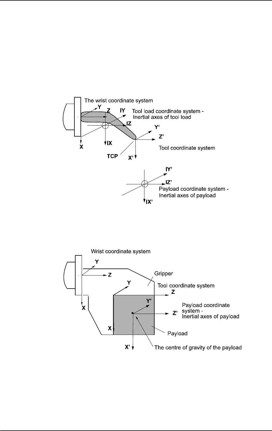
3 Data types
3.29. loaddata - Load data
RobotWare - OS
11333HAC 16581-1 Revision: J
© Copyright 2004-2010 ABB. All rights reserved.
Tool load
The orientation of the tool load coordinate system defined by the principal inertial axes of the
tool load. Expressed in the wrist coordinate system as a quaternion (
q1, q2, q3, q4). If a
stationary tool is used then it means the principal inertial axes for the tool holding the work
object.
Payload
The figure shows restriction on the reorientation of tool load and payload coordinate system.
xx0500002370
The orientation of the payload coordinate system defined by the principal inertial axes of the
payload. Expressed in the tool coordinate system as a quaternion (q1, q2, q3, q4). The object
coordinate system if a stationary tool is used.
The figure shows the center of gravity and inertial axes of the payload.
xx0500002371
Continued
Continues on next page
3 Data types
3.29. loaddata - Load data
RobotWare - OS
3HAC 16581-1 Revision: J1134
© Copyright 2004-2010 ABB. All rights reserved.
ix
inertia x
Data type:
num
The moment of inertia of the load around the x-axis of the tool load or payload coordinate
system in kgm
2
.
Correct definition of the inertial moments will allow optimal utilization of the path planner
and axes control. This may be of special importance when handling large sheets of metal, etc.
All inertial moments of inertia
ix, iy, and iz equal to 0 kgm
2
imply a point mass.
Normally, the inertial moments must only be defined when the distance from the mounting
flange to the center of gravity is less than the dimension of the load (see figure below).
The figure shows that the moment of inertia must normally be defined when the distance is
less than the load dimension.
xx0500002372
iy
inertia y
Data type:
num
The inertial moment of the load around the y-axis, expressed in kgm
2
.
For more information, see
ix.
iz
inertia z
Data type:
num
The inertial moment of the load around the z-axis, expressed in kgm
2
.
For more information, see
ix.
Basic examples
Basic examples of the data type
loaddata are illustrated below.
Example 1
PERS loaddata piece1 := [ 5, [50, 0, 50], [1, 0, 0, 0], 0, 0, 0];
The payload in the first figure in section Payload on page 1133 is described using the
following values:
• Weight 5 kg.
• The center of gravity is x = 50, y = 0 and z = 50 mm in the tool coordinate system.
• The payload is a point mass.
Continued
Continues on next page

3 Data types
3.29. loaddata - Load data
RobotWare - OS
11353HAC 16581-1 Revision: J
© Copyright 2004-2010 ABB. All rights reserved.
Example 2
Set gripper;
WaitTime 0.3;
GripLoad piece1;
Connection of the payload, piece1, specified at the same time as the robot grips the load
piece1.
Example 3
Reset gripper;
WaitTime 0.3;
GripLoad load0;
Disconnection of a payload, specified at the same time as the robot releases a payload.
Limitations
The payload should only be defined as a persistent variable (
PERS) and not within a routine.
Current values are then saved when saving the program and are retrieved on loading.
Arguments of the type
loaddata in the GripLoad instruction should only be an entire
persistent (not array element or record component).
Predefined data
The load
load0 defines a payload, with the mass equal to 0 kg, i.e. no load at all. This load
is used as the argument in the instruction
GripLoad to disconnect a payload.
The load
load0 can always be accessed from the program, but cannot be changed (it is stored
in the system module
BASE).
PERS loaddata load0 := [ 0.001, [0, 0, 0.001], [1, 0, 0, 0],0, 0
,0 ];
Structure
< dataobject of loaddata >
< mass of num >
< cog of pos >
< x of num >
< y of num >
< z of num >
< aom of orient >
< q1 of num >
< q2 of num >
< q3 of num >
< q4 of num >
< ix of num >
< iy of num >
< iz of num >
Continued
Continues on next page

3 Data types
3.29. loaddata - Load data
RobotWare - OS
3HAC 16581-1 Revision: J1136
© Copyright 2004-2010 ABB. All rights reserved.
Related information
For information about See
Coordinate systems Technical reference manual - RAPID overview,
section Motion and I/O principles - Coordinate
systems
Definition of tool loads tooldata - Tool data on page 1207
Activation of payload GripLoad - Defines the payload for the robot on page
119
Continued

3 Data types
3.30. loadidnum - Type of load identification
RobotWare - OS
11373HAC 16581-1 Revision: J
© Copyright 2004-2010 ABB. All rights reserved.
3.30. loadidnum - Type of load identification
Usage
loadidnum is used to represent an integer with a symbolic constant.
Description
A
loadidnum constant is intended to be used for load identification of tool or payload as
arguments in instruction
LoadId. See example below.
Basic examples
Basic examples of the data type
loadidnum are illustrated below.
Example 1
LoadId TOOL_LOAD_ID, MASS_WITH_AX3, gun1;
Load identification of tool gun1 with identification of mass with movements of robot axis 3
with use of predefined constant
MASS_WITH_AX3 of data type loadidnum.
Predefined data
The following symbolic constants of the data type
loadidnum are predefined and can be used
as arguments in instruction
LoadId.
Characteristics
loadidnum is an alias data type for num and consequently inherits its characteristics.
Related information
Value Symbolic constant Comment
1 MASS_KNOWN Known mass in tool or payload respectively.
2 MASS_WITH_AX3 Unknown mass in tool or payload. Identification of mass
will be done with movements of axis 3
For information about See
Predefined program Load Identify Operating manual - IRC5 with FlexPendant,
section Programming and testing - Service
routines - LoadIdentify, load identification and
service routines
Valid robot type ParIdRobValid - Valid robot type for parameter
identification on page 916
Valid robot position ParIdPosValid - Valid robot position for
parameter identification on page 913
Load identification with complete example LoadId - Load identification of tool or payload on
page 212

3 Data types
3.31. loadsession - Program load session
RobotWare - OS
3HAC 16581-1 Revision: J1138
© Copyright 2004-2010 ABB. All rights reserved.
3.31. loadsession - Program load session
Usage
loadsession is used to define different load sessions of RAPID program modules.
Description
Data of the type
loadsession is used in the instructions StartLoad and WaitLoad to
identify the load session.
loadsession only contains a reference to the load session.
Characteristics
loadsession is a non-value data type and cannot be used in value-oriented operations.
Related information
For information about See
Loading program modules during execution StartLoad - Load a program module during
execution on page 482
WaitLoad - Connect the loaded module to the
task on page 682
Characteristics of non-value data types Technical reference manual - RAPID
overview, section Basic characteristics - Data
types

3 Data types
3.32. mecunit - Mechanical unit
RobotWare - OS
11393HAC 16581-1 Revision: J
© Copyright 2004-2010 ABB. All rights reserved.
3.32. mecunit - Mechanical unit
Usage
mecunit is used to define the different mechanical units which can be controlled and
accessed from the program.
The names of the mechanical units are defined in the system parameters and, consequently,
must not be defined in the program.
Description
Data of the type
mecunit only contains a reference to the mechanical unit.
Limitations
Data of the type
mecunit must not be defined in the program. However, if it is then an error
message will be displayed as soon as an instruction or function that refers to this
mecunit is
executed. The data type can, on the other hand, be used as a parameter when declaring a
routine.
Predefined data
All the mechanical units defined in the system parameters are predefined in every program
task. But only the mechanical units that are controlled by the actual program task (defined in
system parameters Controller/Task/Use Mechanical Unit Group) can be used to do any
control operations.
Besides that, the predefined variable
ROB_ID of data type mecunit is available in every
program task. If an actual program task controls a robot then the alias variable
ROB_ID
contains a reference to one of robot
ROB_1 to ROB_6, which can be used to do control
operation on the robot. The variable
ROB_ID is invalid if the actual program task does not
control any robot.
Basic examples
Basic examples of the data type
mecunit are illustrated below.
Example 1
IF TaskRunRob() THEN
IndReset ROB_ID, 6;
ENDIF
If actual program task controls a robot, reset axis 6 for the robot.
Characteristics
mecunit is a non-value data type. This means that data of this type does not permit value-
oriented operations.
Continues on next page

3 Data types
3.32. mecunit - Mechanical unit
RobotWare - OS
3HAC 16581-1 Revision: J1140
© Copyright 2004-2010 ABB. All rights reserved.
Related information
For information about See
Check if task run some robot TaskRunRob - Check if task controls some robot on
page 1014
Check if task run some mechanical
unit
TaskRunMec - Check if task controls any mechanical
unit on page 1013
Get the name of mechanical units in
the system
GetNextMechUnit - Get name and data for
mechanical units on page 852
Activating/Deactivating mechanical
units
ActUnit - Activates a mechanical unit on page 17
DeactUnit - Deactivates a mechanical unit on page 79
Configuration of mechanical units Technical reference manual - System parameters
Characteristics of non-value data
types
Technical reference manual - RAPID overview,
section Basic characteristics - Data types
Continued

3 Data types
3.33. motsetdata - Motion settings data
RobotWare - OS
11413HAC 16581-1 Revision: J
© Copyright 2004-2010 ABB. All rights reserved.
3.33. motsetdata - Motion settings data
Usage
motsetdata is used to define a number of motion settings that affect all positioning
instructions in the program:
• Max. velocity and velocity override
• Acceleration data
• Behavior around singular points
• Management of different robot configurations
• Override of path resolution
• Motion supervision
• Limitation of acceleration/deceleration
• Tool reorientation during circle path
This data type does not normally have to be used since these settings can only be set using
the instructions
VelSet, AccSet, SingArea, ConfJ, ConfL, PathResol, MotionSup,
PathAccLim, CirPathMode, and WorldAccLim.
The current values of these motion settings can be accessed using the system variable
C_MOTSET.
Description
The current motion settings (stored in the system variable
C_MOTSET) affect all movements.
Components
vel.oride
Data type: veldata/num
Velocity as a percentage of programmed velocity.
vel.max
Data type: veldata/num
Maximum velocity in mm/s.
acc.acc
Data type: accdata/num
Acceleration and deceleration as a percentage of the normal values.
acc.ramp
Data type: accdata/num
The rate by which acceleration and deceleration increases as a percentage of the normal
values.
sing.wrist
Data type: singdata/bool
The orientation of the tool is allowed to deviate somewhat in order to prevent wrist
singularity.
Continues on next page

3 Data types
3.33. motsetdata - Motion settings data
RobotWare - OS
3HAC 16581-1 Revision: J1142
© Copyright 2004-2010 ABB. All rights reserved.
sing.arm
Data type: singdata/bool
The orientation of the tool is allowed to deviate somewhat in order to prevent arm singularity
(not implemented).
sing.base
Data type: singdata/bool
The orientation of the tool is not allowed to deviate.
conf.jsup
Data type: confsupdata/bool
Supervision of joint configuration is active during joint movement.
conf.lsup
Data type: confsupdata/bool
Supervision of joint configuration is active during linear and circular movement.
conf.ax1
Data type: confsupdata/num
Maximum permitted deviation in degrees for axis 1 (not used in this version).
conf.ax4
Data type: confsupdata/num
Maximum permitted deviation in degrees for axis 4 (not used in this version).
conf.ax6
Data type: confsupdata/num
Maximum permitted deviation in degrees for axis 6 (not used in this version).
pathresol
Data type: num
Current override in percentage of the configured path resolution.
motionsup
Data type: bool
Mirror RAPID status (TRUE = On and FALSE = Off) of motion supervision function.
tunevalue
Data type: num
Current RAPID override as a percentage of the configured tunevalue for the motion
supervision function.
acclim
Data type: bool
Limitation of tool acceleration along the path. (TRUE = limitation and FALSE = no limitation).
accmax
Data type: num
TCP acceleration limitation in m/s
2
. If acclim is FALSE, the value is always set to -1.
Continued
Continues on next page

3 Data types
3.33. motsetdata - Motion settings data
RobotWare - OS
11433HAC 16581-1 Revision: J
© Copyright 2004-2010 ABB. All rights reserved.
decellim
Data type: bool
Limitation of tool deceleration along the path. (TRUE = limitation and FALSE = no limitation).
decelmax
Data type: num
TCP deceleration limitation in m/s
2
. If decellim is FALSE, the value is always set to -1.
cirpathreori
Data type: num
Tool reorientation during circle path:
0 = Standard method with interpolation in path frame
1 = Modified method with interpolation in object frame
2 = Modified method with programmed tool orientation in
CirPoint
worldacclim
Data type: bool
Limitation of acceleration in world coordinate system. (TRUE = limitation and FALSE = no
limitation).
worldaccmax
Data type: num
Limitation of acceleration in world coordinate system in m/s
2
. If worldacclim is FALSE,
the value is always set to -1.
Limitations
One and only one of the components
sing.wrist, sing.arm or sing.base may have a
value equal to TRUE.
Basic examples
Basic examples of the data type
motsetdata are illustrated below.
Example 1
IF C_MOTSET.vel.oride > 50 THEN
...
ELSE
...
ENDIF
Different parts of the program are executed depending on the current velocity override.
Continued
Continues on next page

3 Data types
3.33. motsetdata - Motion settings data
RobotWare - OS
3HAC 16581-1 Revision: J1144
© Copyright 2004-2010 ABB. All rights reserved.
Predefined data
C_MOTSET describes the current motion settings of the robot and can always be accessed from
the program. On the other hand,
C_MOTSET can only be changed using a number of
instructions, not by assignment.
The following default values for motion parameters are set
• at a cold start-up.
• when a new program is loaded.
• when starting program execution from the beginning.
VAR motsetdata C_MOTSET := [
[ 100, 500 ], -> veldata
[ 100, 100 ], -> accdata
[ FALSE, FALSE, TRUE ], -> singdata
[ TRUE, TRUE, 30, 45, 90 ] -> confsupdata
100, -> path resolution
TRUE, -> motionsup
100, -> tunevalue
FALSE, -> acclim
-1, -> accmax
FALSE, -> decellim
-1, -> decelmax
0, -> cirpathreori
FALSE, -> worldacclim
-1], -> worldaccmax
Structure
<dataobject of motsetdata>
<vel of veldata> ->Affected by instruction VelSet
<oride of num>
<max of num>
<acc of accdata> ->Affected by instruction AccSet
<acc of num>
<ramp of num>
<sing of singdata> ->Affected by instruction SingArea
<wrist of bool>
<arm of bool>
<base of bool>
<conf of confsupdata> ->Affected by instructions ConfJ and ConfL
<jsup of bool>
<lsup of bool>
<ax1 of num>
<ax4 of num>
<ax6 of num>
<pathresol of num> ->Affected by instruction PathResol
<motionsup of bool> ->Affected by instruction MotionSup
<tunevalue of num> ->Affected by instruction MotionSup
<acclim of bool> ->Affected by instruction PathAccLim
Continued
Continues on next page

3 Data types
3.33. motsetdata - Motion settings data
RobotWare - OS
11453HAC 16581-1 Revision: J
© Copyright 2004-2010 ABB. All rights reserved.
<accmax of num> ->Affected by instruction PathAccLim
<decellim of bool> ->Affected by instruction PathAccLim
<decelmax of num> ->Affected by instruction PathAccLim
<cirpathreori of num> ->Affected by instruction CirPathMode
<worldacclim of bool> ->Affected by instruction WorldAccLim
<worldaccmax of num> ->Affected by instruction WorldAccLim
Related information
For information about See
Instructions for setting motion parameters Technical reference manual - RAPID
overview, section RAPID summary - Motion
settings
Continued

3 Data types
3.34. num - Numeric values
RobotWare - OS
3HAC 16581-1 Revision: J1146
© Copyright 2004-2010 ABB. All rights reserved.
3.34. num - Numeric values
Usage
Num is used for numeric values; e.g. counters.
Description
The value of the
num data type may be
• an integer; e.g. -5,
• a decimal number; e.g. 3.45.
It may also be written exponentially; e.g.2E3 (= 2*10^3 = 2000), 2.5E-2 (= 0.025).
Integers between -8388607 and +8388608 are always stored as exact integers.
Decimal numbers are only approximate numbers and therefore should not be used in is equal
to or is not equal to comparisons. In the case of divisions and operations using decimal
numbers, the result will also be a decimal number; i.e. not an exact integer. For example:
a := 10;
b := 5;
IF a/b=2 THEN
...
As the result of a/b is not an integer, this condition is not necessarily satisfied.
Basic examples
Basic examples of the data type
num are illustrated below.
Example 1
VAR num reg1;
...
reg1 := 3;
reg1
is assigned the value 3.
Example 2
a := 10 DIV 3;
b := 10 MOD 3;
Integer division where a is assigned an integer (=3) and b is assigned the remainder (=1).
Predefined data
There is some predefined data in the system. For example the constant pi (π) is defined in the
system module BASE_SHARED.
CONST num pi := 3.1415926;
Limitations
Literal values between -8388607 to 8388608 assigned to a
num variable are stored as exact
integers.
If a literal that has been interpreted as a
dnum is assigned/used as a num, it is automatically
converted to a
num.
Continues on next page

3 Data types
3.34. num - Numeric values
RobotWare - OS
11473HAC 16581-1 Revision: J
© Copyright 2004-2010 ABB. All rights reserved.
Related information
For information about See
Numeric values using datatype dnum dnum - Double numeric values on page 1104
Numeric expressions Technical reference manual - RAPID
overview, section Basic RAPID programming
- Expressions
Operations using numeric values Technical reference manual - RAPID
overview, section Basic RAPID programming
- Expressions
Continued

3 Data types
3.35. opcalc - Arithmetic Operator
RobotWare - OS
3HAC 16581-1 Revision: J1148
© Copyright 2004-2010 ABB. All rights reserved.
3.35. opcalc - Arithmetic Operator
Usage
opcalc is used to represent an arithmetic operator in arguments to RAPID functions or
instructions.
Description
An
opcalc constant is intended to be used to define the type of arithmetic operation.
Examples
Basic example of the usage of datatype
opcalc is illustrated below.
Example 1
res := StrDigCalc(str1, OpAdd, str2);
res
is assigned the result of the addition operation on the values represented by the strings
str1
and str2. OpAdd is of datatype opcalc.
Predefined data
The following symbolic constants of the data type
opcalc are predefined and can be used to
define the type of arithmetic operation used, for instance, in function
StrDigCalc.
Characteristics
opcalc is an alias data type for num and consequently inherits its characteristics.
Related information
Constant Value Comment
OpAdd 1 Addition (+)
OpSub 2 Substraction (-)
OpMult 3 Multiplication (*)
OpDiv 4 Division (/)
OpMod 5 Modulus(%l)
For information about See
Data types in general, alias data types Technical reference manual - RA]PID
overview, section Basic characteristics -
Datatypes
Arithmetic operations on digital strings. StrDigCalc - Arithmetic operations with
datatype stringdig on page 988

3 Data types
3.36. opnum - Comparison operator
RobotWare - OS
11493HAC 16581-1 Revision: J
© Copyright 2004-2010 ABB. All rights reserved.
3.36. opnum - Comparison operator
Usage
opnum is used to represent an operator for comparisons in arguments to RAPID functions or
instructions.
Description
An
opnum constant is intended to be used to define the type of comparison when checking
values in generic instructions.
Basic examples
Basic examples of the data type
opnum are illustrated below.
Example 1
TriggCheckIO checkgrip, 100, airok, EQ, 1, intno1;
Predefined data
The following symbolic constants of the data type
opnum are predefined and can be used to
define the type of comparison used, for instance, in instruction
TriggCheckIO.
Characteristics
opnum is an alias data type for num and consequently inherits its characteristics.
Related information
Value Symbolic constant Comment
1 LT Less than
2 LTEQ Less than or equal to
3 EQ Equal to
4 NOTEQ Not equal to
5 GTEQ Greater than or equal to
6 GT Greater than
For information about See
Data types in general, alias data types Technical reference manual - RAPID
overview, section Basic characteristics - Data
types
Define I/O check at a fixed position TriggCheckIO - Defines IO check at a fixed
position on page 577

3 Data types
3.37. orient - Orientation
RobotWare - OS
3HAC 16581-1 Revision: J1150
© Copyright 2004-2010 ABB. All rights reserved.
3.37. orient - Orientation
Usage
orient is used for orientations (such as the orientation of a tool) and rotations (such as the
rotation of a coordinate system).
Description
The orientation is described in the form of a quaternion which consists of four elements:
q1,
q2, q3, and q4. For more information on how to calculate these, see below.
Components
The data type
orient has the following components:
q1
Data type: num
Quaternion 1.
q2
Data type: num
Quaternion 2.
q3
Data type: num
Quaternion 3.
q4
Data type: num
Quaternion 4.
Basic examples
Basic examples of the data type
orient are illustrated below.
Example 1
VAR orient orient1;
.
orient1 := [1, 0, 0, 0];
The orient1 orientation is assigned the value q1=1, q2-q4=0; this corresponds to no
rotation.
Limitations
The orientation must be normalized; i.e. the sum of the squares must equal 1:
.
Continues on next page
3 Data types
3.37. orient - Orientation
RobotWare - OS
11513HAC 16581-1 Revision: J
© Copyright 2004-2010 ABB. All rights reserved.
What is a Quaternion?
The orientation of a coordinate system (such as that of a tool) can be described by a rotational
matrix that describes the direction of the axes of the coordinate system in relation to a
reference system (see figure below).
xx0500002376
The rotated coordinate systems axes (x, y, z) are vectors which can be expressed in the
reference coordinate system as follows:
x = (x1, x2, x3)
y = (y1, y2, y3)
z = (z1, z2, z3)
This means that the x-component of the x-vector in the reference coordinate system will be
x1, the y-component will be x2, etc.
These three vectors can be put together in a matrix (a rotational matrix) where each of the
vectors form one of the columns:
.
A quaternion is just a more concise way to describe this rotational matrix; the quaternions are
calculated based on the elements of the rotational matrix:
.
.
sign q2 = sign (y3-z2)
.
sign q3 = sign (z1-x3)
.
sign q4 = sign (x2-y1)
Continued
Continues on next page
3 Data types
3.37. orient - Orientation
RobotWare - OS
3HAC 16581-1 Revision: J1152
© Copyright 2004-2010 ABB. All rights reserved.
Example 1
A tool is orientated so that its Z’-axis points straight ahead (in the same direction as the X-
axis of the base coordinate system). The Y’-axis of the tool corresponds to the Y-axis of the
base coordinate system (see figure below). How is the orientation of the tool defined in the
position data (
robtarget)?
The orientation of the tool in a programmed position is normally related to the coordinate
system of the work object used. In this example, no work object is used and the base
coordinate system is equal to the world coordinate system. Thus, the orientation is related to
the base coordinate system.
xx0500002377
The axes will then be related as follows:
x’ = -z = (0, 0, -1)
y’ = y = (0, 1, 0)
z’ = x = (1, 0, 0)
Which corresponds to the following rotational matrix:
.
The rotational matrix provides a corresponding quaternion:
.
.
.
sign q3 = sign (1+1) = +
.
Continued
Continues on next page
3 Data types
3.37. orient - Orientation
RobotWare - OS
11533HAC 16581-1 Revision: J
© Copyright 2004-2010 ABB. All rights reserved.
Example 2
The direction of the tool is rotated 30° about the X’- and Z’-axes in relation to the wrist
coordinate system (see figure below). How is the orientation of the tool defined in the tool
data?
xx0500002378
The axes will then be related as follows:
x’ = (cos30°, 0, -sin30°)
x’ = (0, 1, 0)
x’ = (sin30°, 0, cos30°)
Which corresponds to the following rotational matrix:
.
The rotational matrix provides a corresponding quaternion:
Structure
< dataobject of orient >
< q1 of num >
< q2 of num >
< q3 of num >
< q4 of num >
Related information
.
.
.
sign q3 = sign (sin30°+sin30°) = +
.
For information about See
Operations on orientations Technical reference manual - RAPID
overview, section Basic Characteristics -
Expressions
Continued

3 Data types
3.38. paridnum - Type of parameter identification
RobotWare - OS
3HAC 16581-1 Revision: J1154
© Copyright 2004-2010 ABB. All rights reserved.
3.38. paridnum - Type of parameter identification
Usage
paridnum is used to represent an integer with a symbolic constant.
Description
A
paridnum constant is intended to be used for parameter identification such as load
identification of tool or payload or external manipulator load. See example below.
Basic examples
Basic examples of the data type
paridnum are illustrated below.
Example 1
TEST ParIdRobValid (TOOL_LOAD_ID)
CASE ROB_LOAD_VAL:
! Possible to do load identification of tool in actual robot type
...
CASE ROB_LM1_LOAD_VAL:
! Only possible to do load identification of tool with
! IRB 6400FHD if actual load < 200 kg
...
CASE ROB_NOT_LOAD_VAL:
! Not possible to do load identification of tool in actual robot
type
...
ENDTEST
Use of predefined constant TOOL_LOAD_ID of data type paridnum.
Predefined data
The following symbolic constants of the data type
paridnum are predefined and can be used
as arguments in the following instructions,
ParIdRobValid, ParIdPosValid, LoadId,
and
ManLoadIdProc.
Value Symbolic constant Comment
1 TOOL_LOAD_ID Identify tool load
2 PAY_LOAD_ID Identify payload (Ref. instruction GripLoad)
3 IRBP_K Identify External Manipulator IRBP K load
4 IRBP_L Identify External Manipulator IRBP L load
4 IRBP_C Identify External Manipulator IRBP C load
4 IRBP_C_INDEX Identify External Manipulator IRBP C_INDEX load
4 IRBP_T Identify External Manipulator IRBP T load
5 IRBP_R Identify External Manipulator IRBP R load
6 IRBP_A Identify External Manipulator IRBP A load
6 IRBP_B Identify External Manipulator IRBP B load
6 IRBP_D Identify External Manipulator IRBP D load
Continues on next page

3 Data types
3.38. paridnum - Type of parameter identification
RobotWare - OS
11553HAC 16581-1 Revision: J
© Copyright 2004-2010 ABB. All rights reserved.
NOTE!
Only
TOOL_LOAD_ID and PAY_LOAD_ID can be used in user defined RAPID Programs for
load identification of the tool respectively the pay load for the robot.
Characteristics
paridnum is an alias data type for num and consequently inherits its characteristics.
Related information
For information about See
Predefined program Load Identify Operating manual - IRC5 with FlexPendant,
section Programming and testing - Service
routines - LoadIdentify, load identification and
service routines
Valid robot type ParIdRobValid - Valid robot type for parameter
identification on page 916
Valid robot position ParIdPosValid - Valid robot position for
parameter identification on page 913
Load identification with complete example LoadId - Load identification of tool or payload
on page 212
Load identification of external manipulators ManLoadIdProc - Load identification of IRBP
manipulators on page 219
Continued

3 Data types
3.39. paridvalidnum - Result of ParIdRobValid
RobotWare - OS
3HAC 16581-1 Revision: J1156
© Copyright 2004-2010 ABB. All rights reserved.
3.39. paridvalidnum - Result of ParIdRobValid
Usage
paridvalidnum is used to represent an integer with a symbolic constant.
Description
A
paridvalidnum constant is intended to be used for parameter identification, such as load
identification of tool or payload, when checking the return value from function
ParIdRobValid. See example below.
Basic examples
Basic examples of the data type
paridvalidnum are illustrated below.
TEST ParIdRobValid (PAY_LOAD_ID)
CASE ROB_LOAD_VAL:
! Possible to do load identification of payload in actual robot
! type
...
CASE ROB_LM1_LOAD_VAL:
! Only possible to do load identification of payload
! with IRB 6400FHD if actual load < 200 kg
...
CASE ROB_NOT_LOAD_VAL:
! Not possible to do load identification of payload
! in actual robot type
...
ENDTEST
Use of predefined constants ROB_LOAD_VAL, ROB_LM1_LOAD_VAL and
ROB_NOT_LOAD_VAL
of data type paridvalidnum.
Predefined data
The following symbolic constants of the data type
paridvalidnum are predefined and can
be used for checking the return value from function
ParIdRobValid.
Characteristics
paridvalidnum is an alias data type for num and inherits its characteristics.
Value Symbolic constant Comment
10 ROB_LOAD_VAL Valid robot type for the current parameter identifi-
cation
11 ROB_NOT_LOAD_VAL Not valid robot type for the current parameter
identification
12 ROB_LM1_LOAD_VAL Valid robot type IRB 6400FHD for the current
parameter identification if actual load < 200kg
Continues on next page

3 Data types
3.39. paridvalidnum - Result of ParIdRobValid
RobotWare - OS
11573HAC 16581-1 Revision: J
© Copyright 2004-2010 ABB. All rights reserved.
Related information
For information about See
Predefined program Load Identify Operating manual - IRC5 with FlexPendant, section
Programming and testing - Service routines - LoadIden-
tify, load identification and service routines
Valid robot type ParIdRobValid - Valid robot type for parameter identifi-
cation on page 916
Valid robot position ParIdPosValid - Valid robot position for parameter iden-
tification on page 913
Load identification with complete
example
LoadId - Load identification of tool or payload on page
212
Continued

3 Data types
3.40. pathrecid - Path recorder identifier
Path Recovery
3HAC 16581-1 Revision: J1158
© Copyright 2004-2010 ABB. All rights reserved.
3.40. pathrecid - Path recorder identifier
Usage
pathrecid is used to identify a breakpoint for the path recorder.
Description
The path recorder is a system function for recording the robots executed path. Data of the type
pathrecid can be linked to a specific path location by means of the instruction
PathRecStart. The user can then order the recorder to perform a movement back to the path
identifier by using the instruction
PathRecMoveBwd.
Basic examples
Basic examples of the data type
pathrecid are illustrated below.
Example 1
VAR pathrecid start_id;
CONST robtarget p1 := [...];
CONST robtarget p2 := [...];
CONST robtarget p3 := [...];
PathRecStart start_id;
MoveL p1, vmax, z50, tool1;
MoveL p2, vmax, z50, tool1
MoveL p3, vmax, z50, tool1;
IF(PathRecValidBwd (\ID := start_id)) THEN
StorePath;
PathRecMoveBwd \ID:=start_id;
...
ENDIF
xx0500002090
The example above will start the path recorder and the starting point will be tagged with the
path identifier
start_id. Thereafter, the robot will move forward with traditional move
instructions and then move back to the start position again using the recorded path. To be able
to run PathRecorder move instructions, the path level has to be changed with
StorePath.
Characteristics
pathrecid is an non-value data type.
Continues on next page

3 Data types
3.40. pathrecid - Path recorder identifier
Path Recovery
11593HAC 16581-1 Revision: J
© Copyright 2004-2010 ABB. All rights reserved.
Related information
For information about See
Start - stop the path recorder PathRecStart - Start the path recorder on page
308
PathRecStop - Stop the path recorder on page
311
Check for valid recorded path PathRecValidBwd - Is there a valid backward
path recorded on page 921
PathRecValidFwd - Is there a valid forward
path recorded on page 924
Play the path recorder backward PathRecMoveBwd - Move path recorder
backwards on page 298
Play the path recorder forward PathRecMoveFwd - Move path recorder
forward on page 305
Characteristics of non-value data types Technical reference manual - RAPID overview,
section Basic characteristics - Data types
Continued

3 Data types
3.41. pos - Positions (only X, Y and Z)
RobotWare - OS
3HAC 16581-1 Revision: J1160
© Copyright 2004-2010 ABB. All rights reserved.
3.41. pos - Positions (only X, Y and Z)
Usage
pos is used for positions (only X, Y, and Z).
The
robtarget data type is used for the robot’s position including the orientation of the tool
and the configuration of the axes.
Description
Data of the type
pos describes the coordinates of a position: X, Y, and Z.
Components
The data type
pos has the following components:
x
Data type: num
The X-value of the position.
y
Data type: num
The Y-value of the position.
z
Data type: num
The Z-value of the position.
Basic examples
Basic examples of the data type
pos are illustrated below.
Example 1
VAR pos pos1;
...
pos1 := [500, 0, 940];
The pos1 position is assigned the value: X=500 mm, Y=0 mm, Z=940 mm.
Example 2
pos1.x := pos1.x + 50;
The pos1 position is shifted 50 mm in the X-direction.
Structure
< dataobject of pos >
< x of num >
< y of num >
< z of num >
Continues on next page

3 Data types
3.41. pos - Positions (only X, Y and Z)
RobotWare - OS
11613HAC 16581-1 Revision: J
© Copyright 2004-2010 ABB. All rights reserved.
Related information
For information about See
Operations on positions Technical reference manual - RAPID
overview, section Basic Characteristics -
Expressions
Robot position including orientation robtarget - Position data on page 1176
Continued

3 Data types
3.42. pose - Coordinate transformations
RobotWare - OS
3HAC 16581-1 Revision: J1162
© Copyright 2004-2010 ABB. All rights reserved.
3.42. pose - Coordinate transformations
Usage
pose is used to change from one coordinate system to another.
Description
Data of the type
pose describes how a coordinate system is displaced and rotated around
another coordinate system. The data can, for example, describe how the tool coordinate
system is located and oriented in relation to the wrist coordinate system.
Components
The data type has the following components:
trans
translation
Data type:
pos
The displacement in position (x, y, and z) of the coordinate system.
rot
rotation
Data type:
orient
The rotation of the coordinate system.
Basic examples
Basic examples of the data type
pose are illustrated below.
VAR pose frame1;
...
frame1.trans := [50, 0, 40];
frame1.rot := [1, 0, 0, 0];
The frame1 coordinate transformation is assigned a value that corresponds to a displacement
in position, where X=
50 mm, Y=0 mm, Z=40 mm; there is, however, no rotation.
Structure
< dataobject of pose >
< trans of pos >
< rot of orient >
Related information
For information about See
What is a Quaternion? orient - Orientation on page 1150

3 Data types
3.43. progdisp - Program displacement
RobotWare - OS
11633HAC 16581-1 Revision: J
© Copyright 2004-2010 ABB. All rights reserved.
3.43. progdisp - Program displacement
Usage
progdisp is used to store the current program displacement of the robot and the external
axes.
This data type does not normally have to be used since the data is set using the instructions
PDispSet, PDispOn, PDispOff, EOffsSet, EOffsOn, and EOffsOff. It is only used to
temporarily store the current value for later use.
Description
The current values for program displacement can be accessed using the system variable
C_PROGDISP.
For more information, see the instructions
PDispSet, PDispOn, EOffsSet, and EOffsOn.
Components
pdisp
program displacement
Data type:
pose
The program displacement for the robot, expressed using a translation and an orientation. The
translation is expressed in mm.
eoffs
external offset
Data type:
extjoint
The offset for each of the external axes. If the axis is linear, the value is expressed in mm; if
it is rotating, the value is expressed in degrees.
Basic examples
Basic examples of the data type
progdisp are illustrated below.
Example 1
VAR progdisp progdisp1;
...
SearchL sen1, psearch, p10, v100, tool1;
PDispOn \ExeP:=psearch, *, tool1;
EOffsOn \ExeP:=psearch, *;
...
progdisp1:=C_PROGDISP;
PDispOff;
EOffsOff;
...
PDispSet progdisp1.pdisp;
EOffsSet progdisp1.eoffs;
Continues on next page

3 Data types
3.43. progdisp - Program displacement
RobotWare - OS
3HAC 16581-1 Revision: J1164
© Copyright 2004-2010 ABB. All rights reserved.
First, a program displacement is activated from a searched position. Then, the current
program displacement values are temporary stored in the variable
progdisp1 and the
program displacement is deactivated. Later on, re-activation is done using the instructions
PDispSet and EOffsSet.
Predefined data
The system variable
C_PROGDISP describes the current program displacement of the robot
and external axes, and can always be accessed from the program. On the other hand, it can
only be changed using a number of instructions, not by assignment.
The following default values for program displacement are set
• at a cold start-up.
• when a new program is loaded.
• when starting program execution from the beginning.
VAR progdisp C_PROGDISP :=
[ [[ 0, 0, 0], [1, 0, 0, 0]], -> posedata
[ 0, 0, 0, 0, 0, 0]]; -> extjointdata
Structure
< dataobject of progdisp >
< pdisp of pose >
< trans of pos >
< x of num >
< y of num >
< z of num >
< rot of orient >
< q1 of num >
< q2 of num >
< q3 of num >
< q4 of num >
< eoffs of extjoint >
< eax_a of num >
< eax_b of num >
< eax_c of num >
< eax_d of num >
< eax_e of num >
< eax_f of num >
Related information
For information about See
Instructions for defining program displacement Technical reference manual - RAPID
overview, section RAPID summary - Motion
settings
Coordinate systems Technical reference manual - RAPID
overview, section Motion and I/O principles -
Coordinate systems
Continued

3 Data types
3.44. rawbytes - Raw data
RobotWare - OS
11653HAC 16581-1 Revision: J
© Copyright 2004-2010 ABB. All rights reserved.
3.44. rawbytes - Raw data
Usage
rawbytes is used as a general data container. It can be used for communication with I/O
devices.
Description
rawbytes data can be filled with any type of data - num, byte, string - by means of support
instructions/functions. In any variable of
rawbytes, the system also stores the current length
of valid bytes.
Basic examples
Basic examples of the data type
rawbytes are illustrated below.
Example 1
VAR rawbytes raw_data;
VAR num integer := 8;
VAR num float := 13.4;
ClearRawBytes raw_data;
PackRawBytes integer, raw_data, 1 \IntX := INT;
PackRawBytes float, raw_data, (RawBytesLen(raw_data)+1) \Float4;
In this example the variable raw_data of type rawbytes is first cleared, i.e. all bytes set to
0 (same as default at declaration). Then in the first 2 bytes the value of
integer is placed
and in the next 4 bytes the value of
float.
Limitations
A
rawbytes variable may contain 0 to 1024 bytes.
Structure
rawbytes is a non-value data type.
At declaration of
rawbytes variable, all bytes in rawbytes are set to 0 and the current
length of valid bytes in the variable is set to 0.
Related information
For information about See
Get the length of rawbytes data RawBytesLen - Get the length of rawbytes
data on page 940
Clear the contents of rawbytes data ClearRawBytes - Clear the contents of
rawbytes data on page 49
Copy the contents of rawbytes data CopyRawBytes - Copy the contents of
rawbytes data on page 67
Pack DeviceNet header into rawbytes data PackDNHeader - Pack DeviceNet Header into
rawbytes data on page 287
Pack data into rawbytes data PackRawBytes - Pack data into rawbytes data
on page 290
Continues on next page

3 Data types
3.44. rawbytes - Raw data
RobotWare - OS
3HAC 16581-1 Revision: J1166
© Copyright 2004-2010 ABB. All rights reserved.
Write rawbytes data WriteRawBytes - Write rawbytes data on page
725
Read rawbytes data ReadRawBytes - Read rawbytes data on page
352
Unpack data from rawbytes data UnpackRawBytes - Unpack data from
rawbytes data on page 658
For information about See
Continued

3 Data types
3.45. restartdata - Restart data for trigg signals
RobotWare - OS
11673HAC 16581-1 Revision: J
© Copyright 2004-2010 ABB. All rights reserved.
3.45. restartdata - Restart data for trigg signals
Usage
restartdata mirrors the pre- and postvalues of specified I/O signals (process signals) at the
stop sequence of the robot movements. The I/O signals to supervise are specified in the
instruction
TriggStopProc.
TriggStopProc and restartdata are intended to be used for restart after program stop
(STOP) or emergency stop (QSTOP) of own process instructions defined in RAPID
(NOSTEPIN routines).
Definition
The table shows the definition of the time point for reading the pre- and postvalues for the I/
O signals.
Description
restartdata mirrors the following data after program execution is stopped:
• valid restart data
• robot stopped on path or not
• prevalue of the I/O signals
• postvalue of the I/O signals
• number of flanks between pretime and posttime of the shadow signal for the ongoing
process
Components
restartstop
valid restartdata after stop
Data type:
bool
TRUE = Mirror last STOP or QSTOP
FALSE = Invalid restart data. All I/O signals values are set to -1.
stoponpath
stop on path
Data type:
bool
TRUE = The robot is stopped on the path (STOP)
FALSE = The robot is stopped but not on the path (QSTOP)
Type of stop
Read time for I/O signal
prevalue
Read time for I/O signal
postvalue
STOP on path When all robot axes are standing
still
About 400 ms after the pretime
QSTOP off path As soon as possible About 400 ms after the pretime
Continues on next page

3 Data types
3.45. restartdata - Restart data for trigg signals
RobotWare - OS
3HAC 16581-1 Revision: J1168
© Copyright 2004-2010 ABB. All rights reserved.
predo1val
pre do1 value
Data type:
dionum
The prevalue of the digital signal “do1” specified in the argument DO1 in instruction
TriggStopProc.
postdo1val
post do1 value
Data type:
dionum
The postvalue of the digital signal “do1” specified in the argument DO1 in instruction
TriggStopProc.
prego1val
pre go1 value
Data type:
num
The prevalue of the digital group signal“ go1” specified in the argument GO1 in instruction
TriggStopProc.
postgo1val
post go1 value
Data type:
num
The postvalue of the digital group signal“ go1” specified in the argument GO1 in instruction
TriggStopProc.
prego2val
pre go2 value
Data type:
num
The prevalue of the digital group signal“ go2” specified in the argument GO2 in instruction
TriggStopProc.
postgo2val
post go2 value
Data type:
num
The postvalue of the digital group signal“ go2” specified in the argument GO2 in instruction
TriggStopProc.
prego3val
pre go3 value
Data type:
num
The prevalue of the digital group signal“ go3” specified in the argument GO3 in instruction
TriggStopProc.
postgo3val
post go3 value
Data type:
num
The postvalue of the digital group signal“ go3” specified in the argument GO3 in instruction
TriggStopProc.
Continued
Continues on next page

3 Data types
3.45. restartdata - Restart data for trigg signals
RobotWare - OS
11693HAC 16581-1 Revision: J
© Copyright 2004-2010 ABB. All rights reserved.
prego4val
pre go4 value
Data type:
num
The prevalue of the digital group signal“ go4” specified in the argument GO4 in instruction
TriggStopProc.
postgo4val
post go4 value
Data type:
num
The postvalue of the digital group signal“ go4” specified in the argument GO4 in instruction
TriggStopProc.
preshadowval
pre shadow value
Data type:
dionum
The prevalue of the digital signal “shadow” specified in the argument ShadowDO in
instruction
TriggStopProc.
shadowflanks
number of shadow flanks
Data type:
num
The number of value transitions (flanks) of the digital signal “shadow” between the pretime
and the posttime. The signal “shadow” is specified in the argument
ShadowDO in instruction
TriggStopProc.
postshadowval
post shadow value
Data type:
dionum
The postvalue of the digital signal “shadow” specified in the argument ShadowDO in
instruction
TriggStopProc.
Continued
Continues on next page

3 Data types
3.45. restartdata - Restart data for trigg signals
RobotWare - OS
3HAC 16581-1 Revision: J1170
© Copyright 2004-2010 ABB. All rights reserved.
Structure
< dataobject of restartdata >
< restartstop of bool >
< stoponpath of bool >
< predo1val of dionum >
< postdo1val of dionum >
< prego1val of num >
< postgo1val of num >
< prego2val of num >
< postgo2val of num >
< prego3val of num >
< postgo3val of num >
< prego4val of num >
< postgo4val of num >
< preshadowval of dionum >
< shadowflanks of dionum >
< postshadowval of dionum >
Related information
For information about See
Predefined process instructions TriggL - Linear robot movements with events on
page 603
TriggC - Circular robot movement with events on
page 570
Setup mirror of restart data TriggStopProc - Generate restart data for trigg
signals at stop on page 629
Move backwards on path StepBwdPath - Move backwards one step on path
on page 499
Continued

3 Data types
3.46. rmqheader - RAPID Message Queue Message header
FlexPendant Interface, PC Interface, or Multitasking
11713HAC 16581-1 Revision: J
© Copyright 2004-2010 ABB. All rights reserved.
3.46. rmqheader - RAPID Message Queue Message header
Usage
rmqheader (RAPID Message Queue Header) is used for reading the data structure of the
data in a message of type
rmqmessage.
Description
The header part of a non-value data type
rmqmessage converted to the value data type
rmqheader.
Components
datatype
Data type: string
The name of the data type used, e.g num, string or some other value data type.
ndim
Number of Dimensions
Data type:
num
Number of array dimensions.
dim1
Size of first dimension
Data type:
num
The size of the first dimension. 0 if not used.
dim2
Size of second dimension
Data type:
num
The size of the second dimension. 0 if not used.
dim3
Size of third dimension
Data type:
num
The size of the third dimension. 0 if not used.
Examples
Basic examples of the data type
rmqheader are illustrated below.
Example 1
VAR rmqmessage message;
VAR rmqheader header;
...
RMQGetMessage message;
RMQGetMsgHeader message \Header:=header;
Copy and convert the rmqheader information from an rmqmessage message.
Continues on next page

3 Data types
3.46. rmqheader - RAPID Message Queue Message header
FlexPendant Interface, PC Interface, or Multitasking
3HAC 16581-1 Revision: J1172
© Copyright 2004-2010 ABB. All rights reserved.
Structure
<dataobject of rmqheader>
<datatype of string>
<ndim of num>
<dim1 of num>
<dim2 of num>
<dim3 of num>
Related information
For information about See
Description of the RAPID Message Queue
functionality
Application manual - Robot communication and
I/O control, section RAPID Message Queue.
Extract the header data from an
rmqmessage
RMQGetMsgHeader - Get header information
from an RMQ message on page 380
RMQ Message rmqmessage - RAPID Message Queue
message on page 1173
Continued

3 Data types
3.47. rmqmessage - RAPID Message Queue message
FlexPendant Interface, PC Interface, or Multitasking
11733HAC 16581-1 Revision: J
© Copyright 2004-2010 ABB. All rights reserved.
3.47. rmqmessage - RAPID Message Queue message
Usage
rmqmessage (RAPID Message Queue Message) is used for temporary storage of
communication data.
Description
The data type
rmqmessage is the message used to store data in when communicating
between different RAPID tasks or Robot Application Builder clients with RMQ functionality.
It contains information about the type of data that was sent the dimensions of the data, the
identity of the sender and the actual data.
An
rmqmessage is a big data type (about 3000 bytes big), and it is recommended that the
variable is reused to save RAPID memory.
Basic examples
Basic examples of the data type
rmqmessage are illustrated below.
Example 1
VAR rmqmessage rmqmessage1;
VAR string myrecdata;
...
RMQGetMsgData rmqmessage1, myrecdata;
The variable rmqmessage1 is defined and can be used in an RMQ (RAPID Message Queue)
command. In this example, the data part within the
rmqmessage1 is copied to the variable
myrecdata.
Characteristics
rmqmessage is a non-value data type and cannot be used in value-oriented operations.
Related information
For information about See
Description of the RAPID Message Queue
functionality
Application manual - Robot communication
and I/O control, section RAPID Message
Queue.
RMQ Header rmqheader - RAPID Message Queue
Message header on page 1171
Extract the header data from an
rmqmessage
RMQGetMsgHeader - Get header
information from an RMQ message on page
380
Order and enable interrupts for a specific data
type
IRMQMessage - Orders RMQ interrupts for a
data type on page 167
Get the first message from a RAPID Message
Queue.
RMQGetMessage - Get an RMQ message on
page 373
Send data to the queue of a RAPID task or
Robot Application Builder client, and wait for
an answer from the client.
RMQSendWait - Send an RMQ data
message and wait for a response on page
390
Extract the data from an rmqmessage RMQGetMsgData - Get the data part from an
RMQ message on page 377

3 Data types
3.48. rmqslot - Identity number of an RMQ client
FlexPendant Interface, PC Interface, or Multitasking
3HAC 16581-1 Revision: J1174
© Copyright 2004-2010 ABB. All rights reserved.
3.48. rmqslot - Identity number of an RMQ client
Usage
rmqslot (RAPID Message Queue Slot) is used when communicating with an RMQ or a
Robot Application Builder client.
Description
The
rmqslot is an identity number of a RAPID Message Queue configured for a RAPID task
or the identity number of a Robot Application Builder client.
Basic examples
Basic examples of the data type
rmqslot are illustrated below.
Example 1
VAR rmqslot rmqslot1;
RMQFindSlot rmqslot1, "RMQ_T_ROB1";
...
The variable rmqslot1 is defined and can be used in the instruction RMQFindSlot to get the
identity number of the RAPID Message Queue "
RMQ_T_ROB1" configured for the RAPID
task "
T_ROB1".
Characteristics
rmqslot is a non-value data type and cannot be used in value-oriented operations.
Related information
For information about See
Description of the RAPID Message Queue
functionality
Application manual - Robot communication
and I/O control, section RAPID Message
Queue.
Find the identity number of a RAPID
Message Queue task or Robot Application
Builder client.
RMQFindSlot - Find a slot identity from the
slot name on page 371
Send data to the queue of a RAPID task or
Robot Application Builder client.
RMQSendMessage - Send an RMQ data
message on page 386
Send data to a client, and wait for an answer
from the client.
RMQSendWait - Send an RMQ data
message and wait for a response on page
390
Get the slot name from a specified slot
identity
RMQGetSlotName - Get the name of an
RMQ client on page 964

3 Data types
3.49. robjoint - Joint position of robot axes
RobotWare - OS
11753HAC 16581-1 Revision: J
© Copyright 2004-2010 ABB. All rights reserved.
3.49. robjoint - Joint position of robot axes
Usage
robjoint is used to define the position in degrees of the robot axes.
Description
Data of the type
robjoint is used to store axis positions in degrees of the robot axis 1 to 6.
Axis position is defined as the rotation in degrees for the respective axis (arm) in a positive
or negative direction from the axis calibration position.
Components
rax_1
robot axis 1
Data type:
num
The position of robot axis 1 in degrees from the calibration position.
...
rax_6
robot axis 6
Data type:
num
The position of robot axis 6 in degrees from the calibration position.
Structure
< dataobject of robjoint >
< rax_1 of num >
< rax_2 of num >
< rax_3 of num >
< rax_4 of num >
< rax_5 of num >
< rax_6 of num >
Related information
For information about See
Joint position data jointtarget - Joint position data on page 1129
Move to joint position MoveAbsJ - Moves the robot to an absolute joint
position on page 230

3 Data types
3.50. robtarget - Position data
RobotWare - OS
3HAC 16581-1 Revision: J1176
© Copyright 2004-2010 ABB. All rights reserved.
3.50. robtarget - Position data
Usage
robtarget (robot target) is used to define the position of the robot and external axes.
Description
Position data is used to define the position in the move instructions to which the robot and
external axes are to move.
As the robot is able to achieve the same position in several different ways, the axis
configuration is also specified. This defines the axis values if these are in any way ambiguous,
for example:
• if the robot is in a forward or backward position,
• if axis 4 points downwards or upwards,
• if axis 6 has a negative or positive revolution.
WARNING!
The position is defined based on the coordinate system of the work object, including any
program displacement. If the position is programmed with some other work object than the
one used in the instruction, the robot will not move in the expected way. Make sure that you
use the same work object as the one used when programming move instructions. Incorrect use
can injure someone or damage the robot or other equipment.
Components
trans
translation
Data type:
pos
The position (x, y, and z) of the tool center point expressed in mm.
The position is specified in relation to the current object coordinate system, including
program displacement. If no work object is specified then this is the world coordinate system.
rot
rotation
Data type:
orient
The orientation of the tool, expressed in the form of a quaternion (q1, q2, q3, and q4).
The orientation is specified in relation to the current object coordinate system including
program displacement. If no work object is specified then this is the world coordinate system.
robconf
robot configuration
Data type:
confdata
The axis configuration of the robot (cf1, cf4, cf6, and cfx). This is defined in the form of
the current quarter revolution of axis 1, axis 4, and axis 6. The first positive quarter revolution
0 to 90° is defined as 0. The meaning of the component
cfx is dependent on robot type.
For more information, see data type
confdata.
Continues on next page

3 Data types
3.50. robtarget - Position data
RobotWare - OS
11773HAC 16581-1 Revision: J
© Copyright 2004-2010 ABB. All rights reserved.
extax
external axes
Data type:
extjoint
The position of the external axes.
The position
is defined as follows for each individual axis (eax_a, eax_b ... eax_f):
• For rotating axes, the position is defined as the rotation in degrees from the calibration
position.
• For linear axes, the position is defined as the distance in mm from the calibration
position.
External axes
eax_a ... are logical axes. How the logical axis number and the physical
axis number are related to each other is defined in the system parameters.
The value 9E9 is defined for axes which are not connected. If the axes defined in the position
data differ from the axes that are actually connected at program execution then the following
applies:
• If the position is not defined in the position data (value 9E9) then the value will be
ignored if the axis is connected and not activated. But if the axis is activated then it
will result in an error.
• If the position is defined in the position data although the axis is not connected then
the value is ignored.
No movement is performed but no error is generated for an axis with valid position data if the
axis is not activated.
If some external axis is running in independent mode and some new movement shall be
performed by the robot and it’s external axes then the position data for the external axis is
independent mode must not be 9E9 but some arbitrary value (not used but the system).
Basic examples
Basic examples of the data type
robtarget are illustrated below.
Example 1
CONST robtarget p15 := [ [600, 500, 225.3], [1, 0, 0, 0], [1, 1,
0, 0], [ 11, 12.3, 9E9, 9E9, 9E9, 9E9] ];
A position p15 is defined as follows:
• The position of the robot: x = 600, y = 500 and z = 225.3 mm in the object coordinate
system.
• The orientation of the tool in the same direction as the object coordinate system.
• The axis configuration of the robot: axes 1 and 4 in position 90-180°, axis 6 in position
0-90°.
• The position of the external logical axes, a and b, expressed in degrees or mm
(depending on the type of axis). Axes c to f are undefined.
Continued
Continues on next page

3 Data types
3.50. robtarget - Position data
RobotWare - OS
3HAC 16581-1 Revision: J1178
© Copyright 2004-2010 ABB. All rights reserved.
Example 2
VAR robtarget p20;
...
p20 := CRobT(\Tool:=tool\wobj:=wobjØ);
p20 := Offs(p20,10,0,0);
The position p20 is set to the same position as the current position of the robot by calling the
function
CRobT. The position is then moved 10 mm in the x-direction.
Structure
< dataobject of robtarget >
< trans of pos >
< x of num >
< y of num >
< z of num >
< rot of orient >
< q1 of num >
< q2 of num >
< q3 of num >
< q4 of num >
< robconf of confdata >
< cf1 of num >
< cf4 of num >
< cf6 of num >
< cfx of num >
< extax of extjoint >
< eax_a of num >
< eax_b of num >
< eax_c of num >
< eax_d of num >
< eax_e of num >
< eax_f of num >
Related information
For information about See
Move instructions Technical reference manual - RAPID overview, section
RAPID Summary - Motion
Coordinate systems Technical reference manual - RAPID overview, section
Motion and I/O Principles - Coordinate Systems
Handling configuration data Technical reference manual - RAPID overview, section
Motion and I/O Principles - Robot configuration
Configuration of external axes Application manual - Additional axes and stand alone
controller
What is a quaternion? orient - Orientation on page 1150
Continued

3 Data types
3.51. shapedata - World zone shape data
World Zones
11793HAC 16581-1 Revision: J
© Copyright 2004-2010 ABB. All rights reserved.
3.51. shapedata - World zone shape data
Usage
shapedata is used to describe the geometry of a world zone.
Description
World zones can be defined in 4 different geometrical shapes:
• a straight box, with all sides parallel to the world coordinate system and defined by a
WZBoxDef instruction
• a sphere, defined by a WZSphDef instruction
• a cylinder, parallel to the z axis of the world coordinate system and defined by a
WZCylDef instruction
• a joint space area for robot and/or external axes, defined by the instruction
WZHomeJointDef or WZLimJointDef
The geometry of a world zone is defined by one of the previous instructions and the action of
a world zone is defined by the instruction
WZLimSup or WZDOSet.
Basic examples
Basic examples of the data type
shapedata are illustrated below.
Example 1
VAR wzstationary pole;
VAR wzstationary conveyor;
...
PROC ...
VAR shapedata volume;
...
WZBoxDef \Inside, volume, p_corner1, p_corner2;
WZLimSup \Stat, conveyor, volume;
WZCylDef \Inside, volume, p_center, 200, 2500;
WZLimSup \Stat, pole, volume;
ENDPROC
A conveyor is defined as a box and the supervision for this area is activated. A pole is
defined as a cylinder and the supervision of this zone is also activated. If the robot reaches
one of these areas, the motion is stopped.
Characteristics
shapedata is a non-value data type.
Continues on next page

3 Data types
3.51. shapedata - World zone shape data
World Zones
3HAC 16581-1 Revision: J1180
© Copyright 2004-2010 ABB. All rights reserved.
Related information
For information about See
World Zones Technical reference manual - RAPID overview,
section RAPID summary - Motion settings
Define box-shaped world zone WZBoxDef - Define a box-shaped world zone on
page 732
Define sphere-shaped world zone WZSphDef - Define a sphere-shaped world zone on
page 756
Define cylinder-shaped world zone WZCylDef - Define a cylinder-shaped world zone on
page 734
Define a world zone for home joints WZHomeJointDef - Define a world zone for home
joints on page 746
Define a world zone for limit joints WZLimJointDef - Define a world zone for limitation in
joints on page 749
Activate world zone limit supervision WZLimSup - Activate world zone limit supervision on
page 753
Activate world zone digital output set WZDOSet - Activate world zone to set digital output
on page 738
Continued

3 Data types
3.52. signalxx - Digital and analog signals
RobotWare - OS
11813HAC 16581-1 Revision: J
© Copyright 2004-2010 ABB. All rights reserved.
3.52. signalxx - Digital and analog signals
Usage
Data types within
signalxx are used for digital and analog input and output signals.
The names of the signals are defined in the system parameters and are consequently not to be
defined in the program.
Description
Variables of the type
signalxo only contain a reference to the signal. The value is set using
an instruction, e.g.
DOutput.
Variables of the type
signalxi contain a reference to a signal as well as the possibility to
retrieve the value directly in the program, if used in value context.
The value of an input signal can be read directly in the program, e.g.:
! Digital input
IF di1 = 1 THEN ...
! Digital group input
IF gi1 = 5 THEN ...
! Analog input
IF ai1 > 5.2 THEN ...
It can also be used in assignments, e.g.:
VAR num current_value;
! Digital input
current_value := di1;
! Digital group input
current_value := gi1;
! Analog input
current_value := ai1;
Data type Used for
signalai analog input signals
signalao analog output signals
signaldi digital input signals
signaldo digital output signals
signalgi groups of digital input signals
signalgo groups of digital output signals
Continues on next page

3 Data types
3.52. signalxx - Digital and analog signals
RobotWare - OS
3HAC 16581-1 Revision: J1182
© Copyright 2004-2010 ABB. All rights reserved.
Limitations
Data of the data type
signalxx must not be defined in the program. However, if this is in
fact done then an error message will be displayed as soon as an instruction or function that
refers to this signal is executed. The data type can, on the other hand, be used as a parameter
when declaring a routine.
Predefined data
The signals defined in the system parameters can always be accessed from the program by
using the predefined signal variables (installed data). However, it should be noted that if other
data with the same name is defined then these signals cannot be used.
Characteristics
Signalxo is a non-value data type. Thus, data of this type does not permit value - oriented
operations.
Signalxi is a semi-value data type.
Error handling
The following recoverable error can be generated. The error can be handled in an error
handler. The system variable
ERRNO will be set to:
ERR_NORUNUNIT if there is no contact with the unit.
Related information
For information about See
Summary input/output instructions Technical reference manual - RAPID overview,
section RAPID Summary - Input and output signals
Input/Output functionality in general Technical reference manual - RAPID overview,
section Motion and I/O Principles - I/O principles
Configuration of I/O Technical reference manual - System parameters
Characteristics of non-value data types Technical reference manual - RAPID overview,
section Basic Characteristics - Data types
Continued

3 Data types
3.53. socketdev - Socket device
Socket Messaging
11833HAC 16581-1 Revision: J
© Copyright 2004-2010 ABB. All rights reserved.
3.53. socketdev - Socket device
Usage
socketdev (socket device) is used to communicate with other computers on a network or
between RAPID task.
Description
The socket device is a handle to a communication link to another computer on a network.
Basic examples
Basic examples of the data type
socketdev are illustrated below.
Example 1
VAR socketdev socket1;
The variable socket1 is defined and can be used in a socket command, e.g. SocketCreate.
Limitations
Any number of sockets can be declared but it is only possible to use 8 sockets at the same
time.
Characteristics
socketdev is a non-value data type.
Related information
For information about See
Socket communication in general Application manual - Robot communication and I/O
control
Create a new socket SocketCreate - Create a new socket on page 460
Characteristics of non-value data types Technical reference manual - RAPID overview,
section Basic Characteristics - Data Types

3 Data types
3.54. socketstatus - Socket communication status
Socket Messaging
3HAC 16581-1 Revision: J1184
© Copyright 2004-2010 ABB. All rights reserved.
3.54. socketstatus - Socket communication status
Usage
socketstatus is used for representing status of the socket communication.
Description
Socket status is fetched with the function
SocketGetStatus and can be used for program
flow control or debugging purposes.
Basic examples
Basic examples of the data type
socketstatus are illustrated below.
Example 1
VAR socketdev socket1;
VAR socketstatus state;
...
SocketCreate socket1;
state := SocketGetStatus( socket1 );
The socket status SOCKET_CREATED will be stored in the variable state.
Predefined data
Following constants of type
socketstatus are predefined:
Characteristics
socketstatus is an alias data type for num and consequently inherits its characteristics.
Related information
RAPID constant Value The socket is ...
SOCKET_CREATED 1 Created
SOCKET_CONNECTED 2 Client connected to a remote host
SOCKET_BOUND 3 Server bounded to a local address and port
SOCKET_LISTENING 4 Server listening for incoming connections
SOCKET_CLOSED 5 Closed
For information about See
Socket communication in general Application manual - Robot communication
and I/O control
Get socket status SocketGetStatus - Get current socket state on
page 973
Data types in general, alias data types Technical reference manual - RAPID overview,
section Basic Characteristics - Data Types

3 Data types
3.55. speeddata - Speed data
RobotWare - OS
11853HAC 16581-1 Revision: J
© Copyright 2004-2010 ABB. All rights reserved.
3.55. speeddata - Speed data
Usage
speeddata is used to specify the velocity at which both the robot and the external axes
move.
Description
Speed data defines the velocity:
• at which the tool center point moves,
• the reorientation speed of the tool,
• at which linear or rotating external axes move.
When several different types of movement are combined, one of the velocities often limits all
movements. The velocity of the other movements will be reduced in such a way that all
movements will finish executing at the same time.
The velocity is also restricted by the performance of the robot. This differs, depending on the
type of robot and the path of movement.
Components
v_tcp
velocity tcp
Data type:
num
The velocity of the tool center point (TCP) in mm/s.
If a stationary tool or coordinated external axes are used, the velocity is specified relative to
the work object.
v_ori
velocity orientation
Data type:
num
The reorientation velocity of the TCP expressed in degrees/s.
If a stationary tool or coordinated external axes are used, the velocity is specified relative to
the work object.
v_leax
velocity linear external axes
Data type:
num
The velocity of linear external axes in mm/s.
v_reax
velocity rotational external axes
Data type:
num
The velocity of rotating external axes in degrees/s.
Continues on next page

3 Data types
3.55. speeddata - Speed data
RobotWare - OS
3HAC 16581-1 Revision: J1186
© Copyright 2004-2010 ABB. All rights reserved.
Basic examples
Basic examples of the data type
speeddata are illustrated below.
Example 1
VAR speeddata vmedium := [ 1000, 30, 200, 15 ];
The speed data vmedium is defined with the following velocities:
• 1000 mm/s for the TCP.
• 30 degrees/s for reorientation of the tool.
• 200 mm/s for linear external axes.
• 15 degrees/s for rotating external axes.
vmedium.v_tcp := 900;
The velocity of the TCP is changed to 900 mm/s.
Limitations
At very slow motion each movement should be short enough to give an interpolation time less
than 240 seconds.
Predefined data
A number of speed data are already defined in the system module
BASE_SHARED.
Predefined speed data to be used for moving the robot and the external axes:
Name TCP speed Orientation
Linear
ext. axis
Rotating
ext. axis
v5 5 mm/s 500°/s 5000 mm/s 1000°/s
v10 10 mm/s 500°/s 5000 mm/s 1000°/s
v20 20 mm/s 500°/s 5000 mm/s 1000°/s
v30 30 mm/s 500°/s 5000 mm/s 1000°/s
v40 40 mm/s 500°/s 5000 mm/s 1000°/s
v50 50 mm/s 500°/s 5000 mm/s 1000°/s
v60 60 mm/s 500°/s 5000 mm/s 1000°/s
v80 80 mm/s 500°/s 5000 mm/s 1000°/s
v100 100 mm/s 500°/s 5000 mm/s 1000°/s
v150 150 mm/s 500°/s 5000 mm/s 1000°/s
v200 200 mm/s 500°/s 5000 mm/s 1000°/s
v300 300 mm/s 500°/s 5000 mm/s 1000°/s
v400 400 mm/s 500°/s 5000 mm/s 1000°/s
v500 500 mm/s 500°/s 5000 mm/s 1000°/s
v600 600 mm/s 500°/s 5000 mm/s 1000°/s
v800 800 mm/s 500°/s 5000 mm/s 1000°/s
v1000 1000 mm/s 500°/s 5000 mm/s 1000°/s
v1500 1500 mm/s 500°/s 5000 mm/s 1000°/s
v2000 2000 mm/s 500°/s 5000 mm/s 1000°/s
v2500 2500 mm/s 500°/s 5000 mm/s 1000°/s
v3000 3000 mm/s 500°/s 5000 mm/s 1000°/s
v4000 4000 mm/s 500°/s 5000 mm/s 1000°/s
Continued
Continues on next page

3 Data types
3.55. speeddata - Speed data
RobotWare - OS
11873HAC 16581-1 Revision: J
© Copyright 2004-2010 ABB. All rights reserved.
*) Max. TCP speed for the used robot type and normal practical TCP values. The RAPID
function
MaxRobSpeed returns the same value. If using extreme big TCP values in tool frame
then create own speeddata with bigger TCP speed than returned by
MaxRobSpeed.
Predefined speeddata to be used for moving rotating external axes with instruction
MoveExtJ.
Predefined speed data to be used for moving linear external axes with instruction
MoveExtJ.
Structure
< dataobject of speeddata >
< v_tcp of num >
< v_ori of num >
< v_leax of num >
< v_reax of num >
v5000 5000 mm/s 500°/s 5000 mm/s 1000°/s
v6000 6000 mm/s 500°/s 5000 mm/s 1000°/s
v7000 7000 mm/s 500°/s 5000 mm/s 1000°/s
vmax *) 500°/s 5000 mm/s 1000°/s
Name TCP speed Orientation
Linear
ext. axis
Rotating
ext. axis
vrot1 0 mm/s 0°/s 0 mm/s 1°/s
vrot2 0 mm/s 0°/s 0 mm/s 2°/s
vrot5 0 mm/s 0°/s 0 mm/s 5°/s
vrot10 0 mm/s 0°/s 0 mm/s 10°/s
vrot20 0 mm/s 0°/s 0 mm/s 20°/s
vrot50 0 mm/s 0°/s 0 mm/s 50°/s
vrot100 0 mm/s 0°/s 0 mm/s 100°/s
Name TCP speed Orientation
Linear
ext. axis
Rotating
ext. axis
vlin10 0 mm/s 0°/s 10 mm/s 0°/s
vlin20 0 mm/s 0°/s 20 mm/s 0°/s
vlin50 0 mm/s 0°/s 50 mm/s 0°/s
vlin100 0 mm/s 0°/s 100 mm/s 0°/s
vlin200 0 mm/s 0°/s 200 mm/s 0°/s
vlin500 0 mm/s 0°/s 500 mm/s 0°/s
lin1000 0 mm/s 0°/s 1000 mm/s 0°/s
Name TCP speed Orientation
Linear
ext. axis
Rotating
ext. axis
Continued
Continues on next page

3 Data types
3.55. speeddata - Speed data
RobotWare - OS
3HAC 16581-1 Revision: J1188
© Copyright 2004-2010 ABB. All rights reserved.
Related information
For information about See
Positioning instructions Technical reference manual - RAPID overview, section
RAPID Summary - Motion
Motion/Speed in general Technical reference manual - RAPID overview, section
Motion and I/O principles - Positioning during program
execution
Defining maximum velocity VelSet - Changes the programmed velocity on page 662
Max. TCP speed for this robot MaxRobSpeed - Maximum robot speed on page 892
Continued

3 Data types
3.56. stoppointdata - Stop point data
RobotWare - OS
11893HAC 16581-1 Revision: J
© Copyright 2004-2010 ABB. All rights reserved.
3.56. stoppointdata - Stop point data
Usage
stoppointdata is used to specify how a position is to be terminated, i.e. how close to the
programmed position the axes must be before moving towards the next position.
Description
A position can be terminated either in the form of a fly-by point or a stop point.
A fly-by point means that the programmed position is never reached. A zone is specified in
the instruction for the movement, defining a corner path. Instead of heading for the
programmed position, the direction of the motion is formed into the corner path before the
position is reached. See data type
zonedata.
A stop point means that the robot and external axes must reach the specified position before
the robot/external axes continues with the next movement. The robot is considered to have
reached a stop point when the convergence criteria of the point are satisfied. The convergence
criteria are speed and position. It is also possible to specify timing criteria. For stop point
fine, see also data type zonedata.
Three types of stop points can be defined by the
stoppointdata.
• The in position type of stop point is defined as a percentage of the convergence
criteria (position and speed) for the predefined stop point
fine. The in-position type
also uses a minimum and a maximum time. The robot waits for at least the minimum
time, and at most the maximum time, for the position and speed criteria to be satisfied.
• The stop time type of stop point always waits in the stop point for the given time.
• The follow time type of stop point is a special type of stop point used to coordinate
the robot movement with a conveyor.
The
stoppointdata also determines how the movement shall be synchronized with the
RAPID execution. If the movement is synchronized, the RAPID execution waits for a “in
pos” event when the robot is in position. If the movement is not synchronized, the RAPID
execution gets a “prefetch” event almost a half second before the physical robot reaches the
programmed position. When the program execution gets an “in pos” or a “prefetch” event, it
continues with the next instruction. When the “prefetch” event arrives, the robot still has a
long way to move. When the“ in pos” event arrives the robot is close to the programmed
position.
For the type stop time and follow time, the next instruction starts its execution at the same
time as the stop time and follow time, respectively, start to count down. But for the type in
position, the next instruction is started when the convergence criteria is fulfilled.
If use of move instructions with argument
\Conc, no synchronization at all is done, so the
actual move instruction execution will be ready at once.
Continues on next page
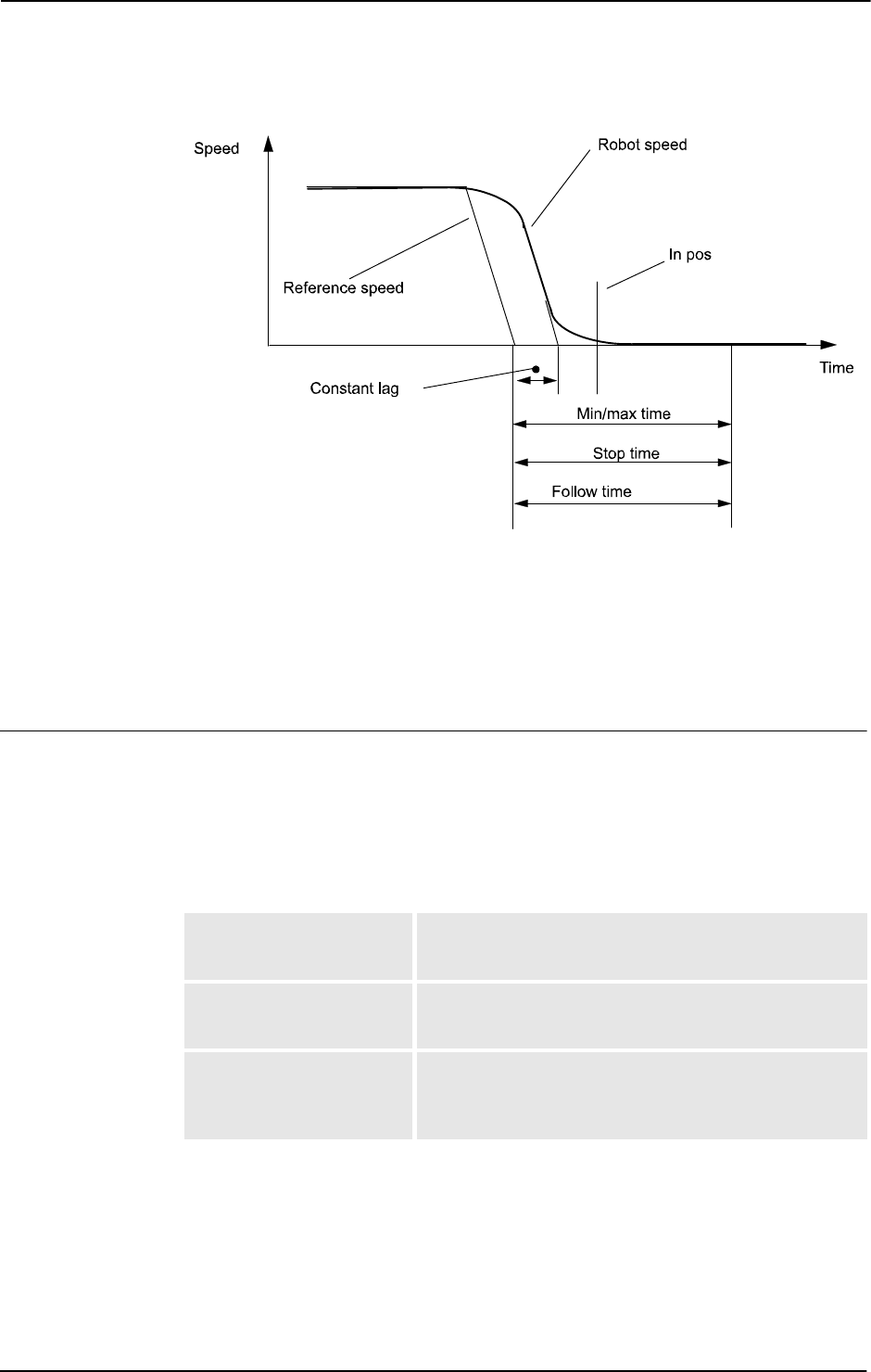
3 Data types
3.56. stoppointdata - Stop point data
RobotWare - OS
3HAC 16581-1 Revision: J1190
© Copyright 2004-2010 ABB. All rights reserved.
xx0500002374
In the figure above, the termination of the stop points is described. The robot’s speed does not
decrease linearly. The robot servo is always ahead of the physical robot. It is shown as the
constant lag in the figure above. The constant lag is about 0.1 seconds. The timing elements
of
stoppointdata use the reference speed as trigger. When the reference speed is zero the
time measurement starts. Therefore the time in the timing elements always include the
constant lag. Consequently there is no sense in using values less than the constant lag.
Components
type
type of stop point
Data type:
stoppoint
The following table defines the type of stoppoint.
1 (inpos) The movement terminates as an in-position type of stop
point. Enables the inpos element in stoppointdata. The
zone data in the instruction is not used, use fine or z0.
2 (stoptime) The movement terminates as a stop-time type of stop point.
Enables the stoptime element in stoppointdata. The
zone data in the instruction is not used, use fine or z0.
3 (followtime) The movement terminates as a conveyor follow-time type of
fine point. The zone data in the instruction is used when the
robot leaves the conveyor. Enables the followtime
element in stoppointdata.
Continued
Continues on next page

3 Data types
3.56. stoppointdata - Stop point data
RobotWare - OS
11913HAC 16581-1 Revision: J
© Copyright 2004-2010 ABB. All rights reserved.
Data type stoppoint is an alias data type for num. It is used to choose the type of stop point
and which data elements to use in the
stoppointdata. Predefined constants are:
progsynch
program synchronization
Data type:
bool
Synchronization with RAPID program execution.
• TRUE: The movement is synchronized with RAPID execution. The program does not
start to execute the next instruction until the stop point has been reached.
• FALSE: The movement is not synchronized with RAPID execution. The program
starts the execution of the next instruction before the stop point has been reached.
If use of move instructions with argument
\Conc, no synchronization at all is done
independent of the data in
progsynch, so the actual move instruction will always be ready
at once.
inpos.position
position condition for TCP
Data type:
num
The position condition (the radius) for the TCP in percent of a normal fine stop point.
inpos.speed
speed condition for TCP
Data type:
num
The speed condition for the TCP in percent of a normal fine stop point.
inpos.mintime
minimum wait time
Data type:
num
The minimum wait time in seconds before in position. Used to make the robot wait at least
the specified time in the point. Maximum value is 20.0 seconds.
inpos.maxtime
maximum wait time
Data type:
num
The maximum wait time in seconds for convergence criteria to be satisfied. Used to assure
that the robot does not get stuck in the point if the speed and position conditions are set too
tight. Maximum value is 20.0 seconds.
Value Symbolic constant Comment
1 inpos In position type number
2 stoptime Stop time type number
3 fllwtime Follow time type number
Continued
Continues on next page

3 Data types
3.56. stoppointdata - Stop point data
RobotWare - OS
3HAC 16581-1 Revision: J1192
© Copyright 2004-2010 ABB. All rights reserved.
stoptime
stop time
Data type:
num
The time in seconds, the TCP stands still in position before starting the next movement. Valid
range 0 - 20 s, resolution 0.001 s.
followtime
follow time
Data type:
num
The time in seconds the TCP follows the conveyor. Valid range 0 - 20 s, resolution 0.001 s.
signal
Data type: string
Reserved for future use.
relation
Data type: opnum
Reserved for future use.
checkvalue
Data type: num
Reserved for future use.
Basic examples
Basic examples of the data type
stoppointdata are illustrated below.
Inpos
VAR stoppointdata my_inpos := [ inpos, TRUE, [ 25, 40, 0.1, 5], 0,
0, "", 0, 0];
MoveL *, v1000, fine \Inpos:=my_inpos, grip4;
The stop point data my_inpos is defined by means of the following characteristics:
• The type of stop point is in-position type, inpos.
• The stop point will be synchronized with the RAPID program execution, TRUE.
• The stop point distance criteria is 25% of the distance defined for the stop point
fine, 25.
• The stop point speed criteria is 40% of the speed defined for the stop point fine, 40.
• The minimum time to wait before convergence is 0,1 s, 0.1.
• The maximum time to wait on convergence is 5 s, 5.
The robot moves towards the programmed position until one of the criteria position or speeds
are satisfied.
my_inpos.inpos.position := 40;
MoveL *, v1000, fine \Inpos:=my_inpos, grip4;
The stop point distance criteria is adjusted to 40%.
Continued
Continues on next page

3 Data types
3.56. stoppointdata - Stop point data
RobotWare - OS
11933HAC 16581-1 Revision: J
© Copyright 2004-2010 ABB. All rights reserved.
Stoptime
VAR stoppointdata my_stoptime := [ stoptime, FALSE, [ 0, 0, 0, 0],
1.45, 0, "", 0, 0];
MoveL *, v1000, fine \Inpos:=my_stoptime, grip4;
The stop point data my_stoptime is defined by means of the following characteristics:
• The type of stop point is stop-time type, stoptime.
• The stop point will not be synchronized with the RAPID program execution, FALSE.
• The wait time in position is 1.45 s.
The robot moves towards the programmed position until the prefetch event arrives. The next
RAPID instruction executes. If it is a move-instruction then the robot stops for
1.45 seconds
before the next movement starts.
my_stoptime.stoptime := 6.66;
MoveL *, v1000, fine \Inpos:=my_stoptime, grip4;
The stop point stop time is adjusted to 6.66 seconds. If the next RAPID instruction is a move-
instruction, the robot stops for
6.66 s.
Followtime
VAR stoppointdata my_followtime := [ fllwtime, TRUE, [ 0, 0, 0,
0], 0, 0.5, "", 0, 0];
MoveL *, v1000, z10 \Inpos:=my_followtime, grip6\wobj:=conveyor1;
The stop point data my_followtime is defined by means of the following characteristics:
• The type of stop point is follow-time type, fllwtime.
• The stop point will be synchronized with the RAPID program execution, TRUE.
• The stop point follow time is 0.5 s, 0.5.
The robot will follow the conveyor for 0.5 s before leaving it with the zone 10 mm,
z10.
my_followtime.followtime := 0.4;
The stop point follow time is adjusted to 0.4 s.
Predefined data
A number of stop point data are already defined in the system module
BASE_SHARED.
In position stop points
(inpos100 has same convergence criteria as stop point fine)
Name Progsynch Position Speed Mintime Maxtime
Stop-
time
Follow-
time
inpos20 TRUE 20% 20% 0 s 2 s - -
inpos50 TRUE 50% 50% 0 s 2 s - -
inpos100 TRUE 100% 100% 0 s 2 s - -
Continued
Continues on next page

3 Data types
3.56. stoppointdata - Stop point data
RobotWare - OS
3HAC 16581-1 Revision: J1194
© Copyright 2004-2010 ABB. All rights reserved.
Stop time stop points
Follow time stop points
Structure
< data object of stoppointdata >
< type of stoppoint >
< progsynch of bool >
< inpos of inposdata >
< position of num >
< speed of num >
< mintime of num >
< maxtime of num >
< stoptime of num >
< followtime of num >
< signal of string >
< relation of opnum >
< checkvalue of num >
Related information
Name Progsynch Position Speed Mintime Maxtime
Stop-
time
Follow-
time
stoptime0_5 FALSE - - - - 0.5 s -
stoptime1_0 FALSE - - - - 1.0 s -
stoptime1_5 FALSE - - - - 1.5 s -
Name Progsynch Position Speed Mintime Maxtime
Stop-
time
Follow-
time
fllwtime0_5 TRUE - - - - - 0.5 s
fllwtime1_0 TRUE - - - - - 1.0 s
fllwtime1_5 TRUE - - - - - 1.5 s
For information about See
Positioning instructions Technical reference manual - RAPID overview,
section RAPID summary - Motion
Movements/Paths in general Technical reference manual - RAPID overview,
section Motion and I/O principles - Positioning
during program execution
Stop or fly-by points zonedata - Zone data on page 1232
Continued

3 Data types
3.57. string - Strings
RobotWare - OS
11953HAC 16581-1 Revision: J
© Copyright 2004-2010 ABB. All rights reserved.
3.57. string - Strings
Usage
string is used for character strings.
Description
A character string consists of a number of characters (a maximum of 80) enclosed by
quotation marks (""), e.g. "This is a character string".
If the quotation marks are to be included in the string, they must be written twice, e.g. "This
string contains a ""character".
If the back slashes are to be included in the string, it must be written twice, e.g. "This string
contains a \\ character".
Basic examples
Basic examples of the data type
string are illustrated below.
Example 1
VAR string text;
...
text := "start welding pipe 1";
TPWrite text;
The text start welding pipe 1 is written on the FlexPendant.
Limitations
A string may have 0 to 80 characters; inclusive of extra quotation marks or back slashes.
A string may contain any of the characters specified by ISO 8859-1 (Latin-1) as well as
control characters (non-ISO 8859-1 (Latin-1) characters with a numeric code between 0-255).
Predefined data
A number of predefined string constants are available in the system and can be used together
with string functions. See for example
StrMemb.
Name Character set
STR_DIGIT <digit> ::=
0 | 1 | 2 | 3 | 4 | 5 | 6 | 7 | 8 | 9
STR_UPPER <upper case letter> ::=
A | B | C | D | E | F | G | H | I | J
| K | L | M | N | O | P | Q | R | S | T
| U | V | W | X | Y | Z | À | Á | Â | Ã
| Ä | Å | Æ | Ç | È | É | Ê | Ë | Ì | Í
| Î | Ï | 1)| Ñ | Ò | Ó | Ô | Õ | Ö | Ø
| Ù | Ú | Û | Ü | 2) | 3)
Continues on next page

3 Data types
3.57. string - Strings
RobotWare - OS
3HAC 16581-1 Revision: J1196
© Copyright 2004-2010 ABB. All rights reserved.
1) Icelandic letter eth.
2) Letter Y with acute accent.
3) Icelandic letter thorn.
The following constants are already defined in the system module
BASE_SHARED:
CONST string diskhome := "HOME:";
! For old programs from S4C system
CONST string ram1disk := "HOME:";
CONST string disktemp := "TEMP:";
CONST string flp1 := "flp1:";
CONST string stSpace := " ";
CONST string stEmpty := "";
stEmpty
can be useful for memory saving if a lot of empty strings are used, for example:
TPReadFK reg1, "warm start required", stEmpty, stEmpty, stEmpty,
stEmpty, "OK";
Related information
STR_LOWER <lower case letter> ::=
a | b | c | d | e | f | g | h | i | j
| k | l | m | n | o | p | q | r | s | t
| u | v | w | x | y | z | à | á | â | ã
| ä | å | æ | ç | è | é | ê | ë | ì | í
| î | ï | 1) | ñ | ò | ó | ô | õ | ö | ø
| ù | ú | û | ü | 2) | 3) | ß | ÿ-
STR_WHITE <blank character> ::=
Name Character set
For information about See
Operations using strings Technical reference manual - RAPID overview, section
Basic characteristics - Expressions
String values Technical reference manual - RAPID overview, section
Basic characteristics - Basic elements
Instruction using character set StrMemb - Checks if a character belongs to a set on
page 1001
Continued

3 Data types
3.58. stringdig - String with only digits
RobotWare - OS
11973HAC 16581-1 Revision: J
© Copyright 2004-2010 ABB. All rights reserved.
3.58. stringdig - String with only digits
Usage
stringdig is used to represent big positive integers in a string with only digits.
This data type is introduced because the data type
num cannot handle positive integers above
8 388 608 with exact representation.
Description
A
stringdig can only consist of a number of digits 0 ... 9 enclosed by quotation marks (""),
e.g. "0123456789".
The data type
stringdig can handle positive integers up to 4 294 967 295.
Basic examples
Basic examples of the data type
stringdig are illustrated below.
Example 1
VAR stringdig digits1;
VAR stringdig digits2;
VAR bool flag1;
...
digits1 ="09000000";
digits2 = "9000001";
flag1 := StrDigCmp (digits1, LT, digits2);
The data flag1 will be set to TRUE because 09000000 is less than 9000001.
Characteristics
stringdig is an alias data type of string and consequently inherits most of its
characteristics.
Related information
For information about See
String values Technical reference manual - RAPID
overview, section Basic characteristics - Basic
elements
Strings string - Strings on page 1195
Numeric values num - Numeric values on page 1146
Comparison operator opnum - Comparison operator on page 1149
StrDigCmp - Compare two strings with only
digits on page 991
Compare strings with only digits StrDigCmp - Compare two strings with only
digits on page 991

3 Data types
3.59. switch - Optional parameters
RobotWare - OS
3HAC 16581-1 Revision: J1198
© Copyright 2004-2010 ABB. All rights reserved.
3.59. switch - Optional parameters
Usage
switch is used for optional parameters.
Description
The special type,
switch may (only) be assigned to optional parameters and provides a
means to use switch arguments, i.e. arguments that are only specified by names (not values).
A value can not be transmitted to a switch parameter. The only way to use a switch parameter
is to check for its presence using the predefined function
Present.
Basic examples
Basic examples of the data type
switch are illustrated below.
Example 1
PROC my_routine(\switch on | \switch off)
....
IF Present (off) THEN
....
ENDIF
ENDPROC
Depending on what arguments the caller of my_routine uses, the program flow can be
controlled.
Characteristics
switch is a non-value data type and can not be used in value-orientated operations.
Related information
For information about See
Parameters Technical reference manual - RAPID
overview, section Basic characteristics -
Routines.
How to check if an optional parameter is
present
Present - Tests if an optional parameter is
used on page 937

3 Data types
3.60. symnum - Symbolic number
RobotWare - OS
11993HAC 16581-1 Revision: J
© Copyright 2004-2010 ABB. All rights reserved.
3.60. symnum - Symbolic number
Usage
symnum (Symbolic Number) is used to represent an integer with a symbolic constant.
Description
A
symnum constant is intended to be used when checking the return value from the functions
OpMode and RunMode. See example below.
Basic examples
Basic examples of the data type
symnum are illustrated below.
Example 1
IF RunMode() = RUN_CONT_CYCLE THEN
..
ELSE
..
ENDIF
Predefined data
The following symbolic constants of the data type
symnum are predefined and can be used
when checking return values from the functions
OpMode and RunMode.
Characteristics
Symnum is an alias data type for num and consequently inherits its characteristics.
Related information
Value Symbolic constant Comment
0 RUN_UNDEF Undefined running mode
1 RUN_CONT_CYCLE Continuous or cycle running mode
2 RUN_INSTR_FWD Instruction forward running mode
3 RUN_INSTR_BWD Instruction backward running mode
4 RUN_SIM Simulated running mode
5 RUN_STEP_MOVE Move instructions in forward running mode and
logical instructions in continuous running mode
Value Symbolic constant Comment
0 OP_UNDEF Undefined operating mode
1 OP_AUTO Automatic operating mode
2 OP_MAN_PROG Manual operating mode max. 250 mm/s
3 OP_MAN_TEST Manual operating mode full speed, 100%
For information about See
Data types in general, alias data types Technical reference manual - RAPID overview,
section Basic characteristics - Data types

3 Data types
3.61. syncident - Identity for synchronization point
Multitasking
3HAC 16581-1 Revision: J1200
© Copyright 2004-2010 ABB. All rights reserved.
3.61. syncident - Identity for synchronization point
Usage
syncident (synchronization identity) is used to specify the name of a synchronization point.
The name of the synchronization point will be the name (identity) of the declared data of type
syncident.
Description
syncident is used to identify a point in the program where the actual program task will wait
for cooperate program tasks to reach the same synchronization point.
The data name (identity) of the type
syncident must be the same in all cooperative program
tasks.
Data type syncident is used in the instructions
WaitSyncTask, SyncMoveOn, and
SyncMoveOff.
Basic examples
Basic examples of the data type
syncident are illustrated below.
Example 1
Program example in program task ROB1
PERS tasks task_list{3} := [ ["STN1"], ["ROB1"], ["ROB2"] ];
VAR syncident sync1;
WaitSyncTask sync1, task_list;
At execution of instruction WaitSyncTask in the program task ROB1, the execution in that
program task will wait until the other program tasks
STN1 and ROB2 have reached their
corresponding
WaitSyncTask with the same synchronization (meeting) point sync1.
Structure
syncident is a non-value data type.
Related information
For information about See
Specify cooperated program tasks tasks - RAPID program tasks on page 1204
Wait for synchronization point with other
tasks
WaitSyncTask - Wait at synchronization point
for other program tasks on page 688
Start coordinated synchronized movements SyncMoveOn - Start coordinated synchro-
nized movements on page 534
End coordinated synchronized movements SyncMoveOff - End coordinated synchro-
nized movements on page 528

3 Data types
3.62. System data - Current RAPID system data settings
RobotWare - OS
12013HAC 16581-1 Revision: J
© Copyright 2004-2010 ABB. All rights reserved.
3.62. System data - Current RAPID system data settings
Usage
System data mirrors the current settings of RAPID system data such as current model
motion settings, current error recovery number
ERRNO, current interrupt number INTNO, etc.
These data can be accessed and read by the program. It can be used to read the current status,
e.g. the current program displacement.
C_MOTSET
The variable C_MOTSET of data type motsetdata mirrors the current motion settings:
C_PROGDISP
The variable C_PROGDISP of data type progdisp mirrors the current program displacement
and external axes offset:
Description Data type Changed by See also
Current motion
settings, i.e.:
motsetdata Instructions motsetdata - Motion settings data
on page 1141
Velocity override and
max velocity
VelSet VelSet - Changes the programmed
velocity on page 662
Acceleration override AccSet AccSet - Reduces the acceleration
on page 15
Movements around
singular points
SingArea SingArea - Defines interpolation
around singular points on page 447
Linear configuration
control
Joint configuration
control
ConfL
ConfJ
ConfL - Monitors the configuration
during linear movement on page 61
ConfJ - Controls the configuration
during joint movement on page 59
Path resolution PathResol PathResol - Override path
resolution on page 314
Tuning motion
supervision
MotionSup MotionSup - Deactivates/Activates
motion supervision on page 227
Reduction of TCP
acceleration/decelera-
tion along the
movement path
PathAccLim PathAccLim - Reduce TCP acceler-
ation along the path on page 295
Modification of the tool
orientation during
circle interpolation
CirPathMode CirPathMode - Tool reorientation
during circle path on page 38
Reduction of payload
acceleration in world
coordinate system
WorldAccLim WorldAccLim - Control acceleration
in world coordinate system on page
707
Description Data type Changed by See also
Current program dis-
placement for robot
axes
progdisp Instructions: progdisp - Program displacement
on page 1163
PDispSet PDispSet - Activates program dis-
placement using known frame on
page 321
PDispOn PDispOn - Activates program dis-
placement on page 317
Continues on next page

3 Data types
3.62. System data - Current RAPID system data settings
RobotWare - OS
3HAC 16581-1 Revision: J1202
© Copyright 2004-2010 ABB. All rights reserved.
ERRNO
The variable ERRNO of data type errnum mirrors the current error recovery number:
INTNO
The variable INTNO of data type intnum mirrors the current interrupt number:
ROB_ID
The variable ROB_ID of data type mecunit contains a reference to the TCP-robot (if any) in
the actual program task.
PDispOff PDispOff - Deactivates program
displacement on page 316
Current external axes
offset
EOffsSet EOffsSet - Activates an offset for
external axes using known values
on page 90
EOffsOn EOffsOn - Activates an offset for
external axes on page 88
EOffsOff EOffsOff - Deactivates an offset for
external axes on page 87
Description Data type Changed by See also
Description Data type Changed by See also
The latest error that
occurred
errnum The system Technical reference manual -
RAPID overview, section RAPID
summary - Error recovery
intnum - Interrupt identity on page
1125
Description Data type Changed by See also
The latest interrupt
that occurred
intnum The system Technical reference manual -
RAPID overview, section RAPID
summary - Interrupts
intnum - Interrupt identity on page
1125
Description Data type Changed by See also
Reference to the robot
(if any) in the actual
program task. Always
check before use with
TaskRunRob ()
mecunit The system mecunit - Mechanical unit on page
1139
Continued

3 Data types
3.63. taskid - Task identification
Multitasking
12033HAC 16581-1 Revision: J
© Copyright 2004-2010 ABB. All rights reserved.
3.63. taskid - Task identification
Usage
taskid is used to identify available program tasks in the system.
The names of the program tasks are defined in the system parameters and, consequently, must
not be defined in the program.
Description
Data of the type
taskid only contains a reference to the program task.
Limitations
Data of the type
taskid must not be defined in the program. The data type can, on the other
hand, be used as a parameter when declaring a routine.
Predefined data
The program tasks defined in the system parameters can always be accessed from the
program (installed data).
For all program tasks in the system, predefined variables of the data type
taskid will be
available. The variable identity will be "taskname"+"Id", e.g. for the
T_ROB1 task the variable
identity will be
T_ROB1Id, T_ROB2 - T_ROB2Id etc.
Characteristics
taskid is a non-value data type. This means that data of this type does not permit value-
oriented operations.
Related information
For information about See
Saving program modules Save - Save a program module on page 396
Configuration of program tasks Technical reference manual - System
parameters
Characteristics of non-value data types Technical reference manual - RAPID
overview, section Basic characteristics - Data
types

3 Data types
3.64. tasks - RAPID program tasks
Multitasking
3HAC 16581-1 Revision: J1204
© Copyright 2004-2010 ABB. All rights reserved.
3.64. tasks - RAPID program tasks
Usage
tasks is used to specify several RAPID program tasks.
Description
To specify several RAPID program tasks, the name of each task can be given as a string. An
array of data type
tasks can then hold all the task names.
This task list can then be used in the instructions
WaitSyncTask and SyncMoveOn.
NOTE!
The instructions above demand that the data is defined as system global
PERS variables
available in all the cooperated tasks.
Components
The data type has the following components.
taskname
Data type: string
The name of a RAPID program task specified in a string.
Basic examples
Basic examples of the data type
tasks are illustrated below.
Example 1
Program example in program task T_ROB1
PERS tasks task_list{3} := [ ["T_STN1"], ["T_ROB1"], ["T_ROB2"] ];
VAR syncident sync1;
WaitSyncTask sync1, task_list;
At execution of instruction WaitSyncTask in the program task T_ROB1, the execution in that
program task will wait until all the other program tasks
T_STN1 and T_ROB2 have reached
their corresponding
WaitSyncTask with the same synchronization (meeting) point sync1.
Structure
<dataobject of tasks>
<taskname of string>
Continues on next page

3 Data types
3.64. tasks - RAPID program tasks
Multitasking
12053HAC 16581-1 Revision: J
© Copyright 2004-2010 ABB. All rights reserved.
Related information
For information about See
Identity for synchronization point syncident - Identity for synchronization point on page
1200
Wait for synchronization point with
other tasks
WaitSyncTask - Wait at synchronization point for other
program tasks on page 688
Start coordinated synchronized
movements
SyncMoveOn - Start coordinated synchronized
movements on page 534
End coordinated synchronized
movements
SyncMoveOff - End coordinated synchronized
movements on page 528
Continued

3 Data types
3.65. testsignal - Test signal
RobotWare - OS
3HAC 16581-1 Revision: J1206
© Copyright 2004-2010 ABB. All rights reserved.
3.65. testsignal - Test signal
Usage
The data type
testsignal is used when a test of the robot motion system is performed.
Description
A number of predefined test signals are available in the robot system. The
testsignal data
type is available in order to simplify programming of instruction
TestSignDefine.
Basic examples
Basic examples of the data type
testsignal are illustrated below.
Example 1
TestSignDefine 2, speed, Orbit, 2, 0;
The predefined constant speed is used to read the actual speed of axis 2 on the manipulator
orbit.
Predefined data
The following test signals for external manipulator axes are predefined in the system. All data
is in SI units and measured on the motor side of the axis.
Characteristics
testsignal is an alias data type for num and consequently inherits its characteristics.
Related information
Symbolic constant Value Unit
speed 6 rad/s
torque_ref 9 Nm
resolver_angle 1 rad
speed_ref 4 rad/s
dig_input1 102 0 or 1
dig_input2 103 0 or 1
For information about See
Define test signal TestSignDefine - Define test signal on page 551
Read test signal TestSignRead - Read test signal value on page 1020
Reset test signals TestSignReset - Reset all test signal definitions on
page 553

3 Data types
3.66. tooldata - Tool data
RobotWare - OS
12073HAC 16581-1 Revision: J
© Copyright 2004-2010 ABB. All rights reserved.
3.66. tooldata - Tool data
Usage
tooldata is used to describe the characteristics of a tool, e.g. a welding gun or a gripper.
If the tool is fixed in space (a stationary tool), the tool data defines this tool and the gripper
holding the work object.
Description
Tool data affects robot movements in the following ways:
• The tool center point (TCP) refers to a point that will satisfy the specified path and
velocity performance. If the tool is reorientated or if coordinated external axes are
used, only this point will follow the desired path at the programmed velocity.
• If a stationary tool is used, the programmed speed and path will relate to the work
object held by the robot.
• Programmed positions refer to the position of the current TCP and the orientation in
relation to the tool coordinate system. This means that if, for example, a tool is
replaced because it is damaged, the old program can still be used if the tool coordinate
system is redefined.
Tool data is also used when jogging the robot to:
• Define the TCP that is not to move when the tool is reorientated.
• Define the tool coordinate system in order to facilitate moving in or rotating in the tool
directions.
WARNING!
It is important to always define the actual tool load and, when used, the payload of the robot
too. Incorrect definitions of load data can result in overloading of the robot mechanical
structure.
When incorrect tool load data is specified, it can often lead to the following consequences:
1. If the value in the specified load is greater than the true load:
• The robot will not be used to its maximum capacity
• Impaired path accuracy including a risk of overshooting
2. If the value in the specified load is less than the true load:
• Risk of overloading the mechanical structure
• Impaired path accuracy including a risk of overshooting
Components
robhold
robot hold
Data type:
bool
Defines whether or not the robot is holding the tool:
• TRUE: The robot is holding the tool.
• FALSE: The robot is not holding the tool, i.e. a stationary tool.
Continues on next page
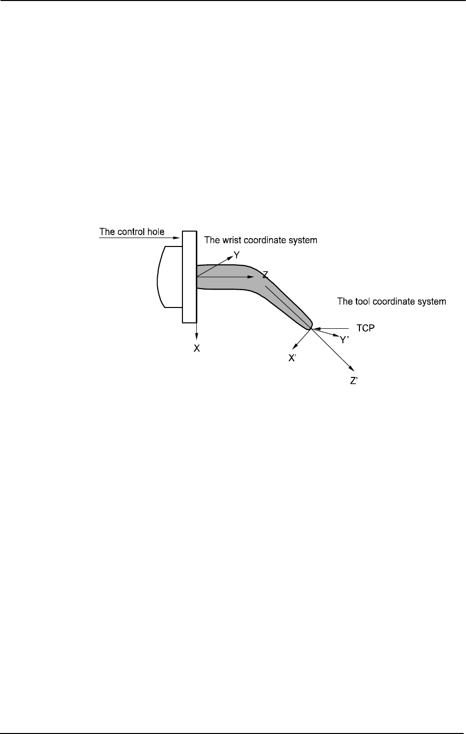
3 Data types
3.66. tooldata - Tool data
RobotWare - OS
3HAC 16581-1 Revision: J1208
© Copyright 2004-2010 ABB. All rights reserved.
tframe
tool frame
Data type:
pose
The tool coordinate system, i.e.:
• The position of the TCP (x, y and z) in mm, expressed in the wrist coordinate system
(see figure below).
• The orientation of the tool coordinate system, expressed in the wrist coordinate system
as a quaternion (q1, q2, q3 and q4) (see figure below).
If a stationary tool is used, the definition is defined in relation to the world coordinate system.
If the direction of the tool is not specified, the tool coordinate system and the wrist coordinate
system will coincide.
xx0500002366
tload
tool load
Data type:
loaddata
The load of the tool, i.e.:
• The weight of the tool in kg.
• The center of gravity of the tool load (x, y and z) in mm, expressed in the wrist
coordinate system
• The moments of inertia of the tool relative to its center of mass around the tool load
coordinate axes in kgm
2
. If all inertial components are defined as being 0 kgm
2
, the
tool is handled as a point mass.
Continued
Continues on next page
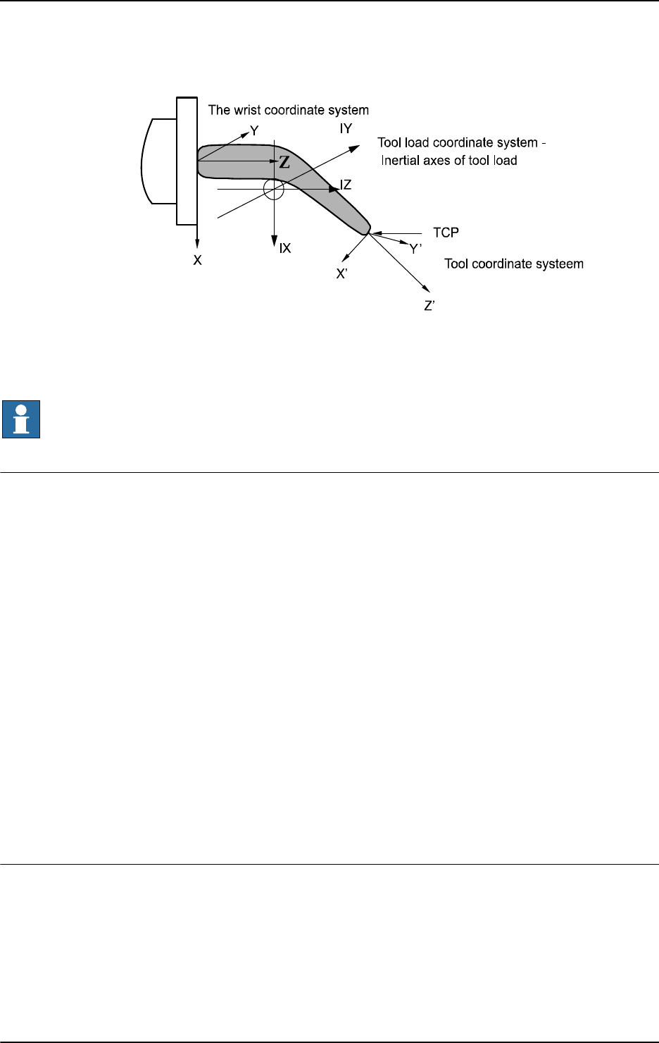
3 Data types
3.66. tooldata - Tool data
RobotWare - OS
12093HAC 16581-1 Revision: J
© Copyright 2004-2010 ABB. All rights reserved.
xx0500002367
For more information (such as coordinate system for stationary tool or restrictions), see the
data type
loaddata.
If a stationary tool is used, the load of the gripper holding the work object is defined in
tload.
NOTE!
Only the load of the tool is to be specified. The payload handled by a gripper is connected and
disconnected by means of the instruction
GripLoad.
Basic examples
Basic examples of the data type
tooldata are illustrated below.
Example 1
PERS tooldata gripper := [ TRUE, [[97.4, 0, 223.1], [0.924, 0,
0.383 ,0]], [5, [23, 0, 75], [1, 0, 0, 0], 0, 0, 0]];
The tool is described using the following values:
• The robot is holding the tool.
• The TCP is located at a point 223.1 mm straight out from axis 6 and 97.4 mm along
the X-axis of the wrist coordinate system.
• The X and Z directions of the tool are rotated 45° in relation to the wrist coordinate
system.
• The tool mass is 5 kg.
• The center of gravity is located at a point 75 mm straight out from axis 6 and 23 mm
along the X-axis of the wrist coordinate system.
• The load can be considered a point mass, i.e. without any moment of inertia.
gripper.tframe.trans.z := 225.2;
The TCP of the tool, gripper, is adjusted to 225.2 in the z-direction.
Limitations
The tool data should be defined as a persistent variable (
PERS) and should not be defined
within a routine. The current values are then saved when the program is saved and are
retrieved on loading.
Arguments of the type tool data in any motion instruction should only be an entire persistent
(not array element or record component).
Continued
Continues on next page

3 Data types
3.66. tooldata - Tool data
RobotWare - OS
3HAC 16581-1 Revision: J1210
© Copyright 2004-2010 ABB. All rights reserved.
Predefined data
The tool
tool0 defines the wrist coordinate system, with the origin being the center of the
mounting flange.
Tool0 can always be accessed from the program, but can never be changed
(it is stored in system module BASE).
PERS tooldata tool0 := [ TRUE, [ [0, 0, 0], [1, 0, 0 ,0] ], [0.001,
[0, 0, 0.001], [1, 0, 0, 0], 0, 0, 0] ];
Structure
< dataobject of tooldata >
< robhold of bool >
< tframe of pose >
< trans of pos >
< x of num >
< y of num >
< z of num >
< rot of orient >
< q1 of num >
< q2 of num >
< q3 of num >
< q4 of num >
< tload of loaddata >
< mass of num >
< cog of pos >
< x of num >
< y of num >
< z of num >
< aom of orient >
< q1 of num >
< q2 of num >
< q3 of num >
< q4 of num >
< ix of num >
< iy of num >
< iz of num >
Related information
For information about See
Positioning instructions Technical reference manual - RAPID overview,
section RAPID summary - Motion
Coordinate systems Technical reference manual - RAPID overview,
section Motion and I/O Principles - Coordinate
systems
Definition of payload GripLoad - Defines the payload for the robot on page
119
Definition of load loaddata - Load data on page 1132
Continued

3 Data types
3.67. tpnum - FlexPendant window number
RobotWare - OS
12113HAC 16581-1 Revision: J
© Copyright 2004-2010 ABB. All rights reserved.
3.67. tpnum - FlexPendant window number
Usage
tpnum is used to represent the FlexPendant window number with a symbolic constant.
Description
A
tpnum constant is intended to be used in instruction TPShow. See example below.
Basic examples
Basic examples of the datatype
tpnum are illustrated below.
Example 1
TPShow TP_LATEST;
The last used FlexPendant Window before the current FlexPendant window will be active
after execution of this instruction.
Predefined data
The following symbolic constant of the data type
tpnum is predefined and can be used in
instruction
TPShow:
Characteristics
tpnum is an alias data type for num and consequently inherits its characteristics.
Related information
Value Symbolic constant Comment
2 TP_LATEST Latest used FlexPendant window
Information about See
Data types in general, alias data types Technical reference manual - RAPID overview,
section Basic Characteristics - Data Types
Communicating using the FlexPendant Technical reference manual - RAPID overview,
section RAPID Summary - Communication
Switch window on the FlexPendant TPShow - Switch window on the FlexPendant
on page 567

3 Data types
3.68. trapdata - Interrupt data for current TRAP
RobotWare - OS
3HAC 16581-1 Revision: J1212
© Copyright 2004-2010 ABB. All rights reserved.
3.68. trapdata - Interrupt data for current TRAP
Usage
trapdata (trap data) is used to contain the interrupt data that caused the current TRAP
routine to be executed.
To be used in
TRAP routines generated by instruction IError, before use of the instruction
ReadErrData.
Description
Data of the type
trapdata represents internal information related to the interrupt that caused
the current trap routine to be executed. Its content depends on the type of interrupt.
Basic examples
Basic examples of the data type
trapdata are illustrated below.
Example 1
VAR errdomain err_domain;
VAR num err_number;
VAR errtype err_type;
VAR trapdata err_data;
...
TRAP trap_err
GetTrapData err_data;
ReadErrData err_data, err_domain, err_number, err_type;
ENDTRAP
When an error is trapped to the trap routine trap_err, the error domain, the error number,
and the error type are saved into appropriate non-value variables of type
trapdata.
Characteristics
trapdata is a non-value data type.
Related information
For information about See
Summary of interrupts Technical reference manual - RAPID
overview, section RAPID summary - Interrupts
More information on interrupt management Technical reference manual - RAPID
overview, section Basic characteristics -
Interrupts
Non value data types Technical reference manual - RAPID
overview, section Basic characteristics - Data
types
Orders an interrupt on errors IError - Orders an interrupt on errors on page
126
Get interrupt data for current TRAP GetTrapData - Get interrupt data for current
TRAP on page 115
Gets information about an error ReadErrData - Gets information about an
error on page 349

3 Data types
3.69. triggdata - Positioning events, trigg
RobotWare - OS
12133HAC 16581-1 Revision: J
© Copyright 2004-2010 ABB. All rights reserved.
3.69. triggdata - Positioning events, trigg
Usage
triggdata is used to store data about a positioning event during a robot movement.
A positioning event can take the form of setting an output signal or running an interrupt
routine at a specific position along the movement path of the robot.
Description
To define the conditions for the respective measures at a positioning event, variables of the
type
triggdata are used. The data contents of the variable are formed in the program using
one of the instructions
TriggIO, TriggEquip, TriggCheckIO or TriggInt, and are used
by one of the instructions
TriggL, TriggC or TriggJ.
Basic examples
Basic examples of the data type
triggdata are illustrated below.
Example 1
VAR triggdata gunoff;
TriggIO gunoff, 0,5 \DOp:=gun, 0;
TriggL p1, v500, gunoff, fine, gun1;
The digital output signal gun is set to the value 0 when the TCP is at a position 0,5 mm
before the point
p1.
Characteristics
triggdata is a non-value data type.
Related information
For information about See
Definition of triggs TriggIO - Define a fixed position or time I/O event
near a stop point on page 592
TriggEquip - Define a fixed position and time I/O
event on the path on page 582
TriggCheckIO - Defines IO check at a fixed
position on page 577
TriggInt - Defines a position related interrupt on
page 588
Use of triggs TriggL - Linear robot movements with events on
page 603
TriggC - Circular robot movement with events on
page 570
TriggJ - Axis-wise robot movements with events
on page 597
Characteristics of non-value data types Technical reference manual - RAPID overview,
section Basic characteristics - Data types

3 Data types
3.70. triggios - Positioning events, trigg
RobotWare - OS
3HAC 16581-1 Revision: J1214
© Copyright 2004-2010 ABB. All rights reserved.
3.70. triggios - Positioning events, trigg
Usage
triggiosis used to store data about a positioning event during a robot movement. When the
positioning event is distributed at a specific position on the path, an output signal is set to a
specified value.
Description
triggios is used to define conditions and actions for setting a digital output signal, a group
of digital output signals or an analog output signal at a fixed position along the robot’s
movement path.
Components
used
Data type: bool
Defines whether or not the array element should be used or not.
distance
Data type: num
Defines the position on the path where the I/O event shall occur. Specified as the distance in
mm (positive value) from the end point of the movement path if component
start is set to
FALSE.
start
Data type: bool
Set to TRUE when the distance starts at the movement start point instead of the end point.
equiplag
Equipment Lag
Data type:
num
Specify the lag for the external equipment in s.
For compensation of external equipment lag, use a positive argument value. Positive value
means that the I/O signal is set by the robot system at a specified time before the TCP
physically reaches the specified distance in relation to the movement start or end point.
Negative value means that the I/O signal is set by the robot system at a specified time after
that the TCP has physically passed the specified distance in relation to the movement start or
end point.
Continues on next page
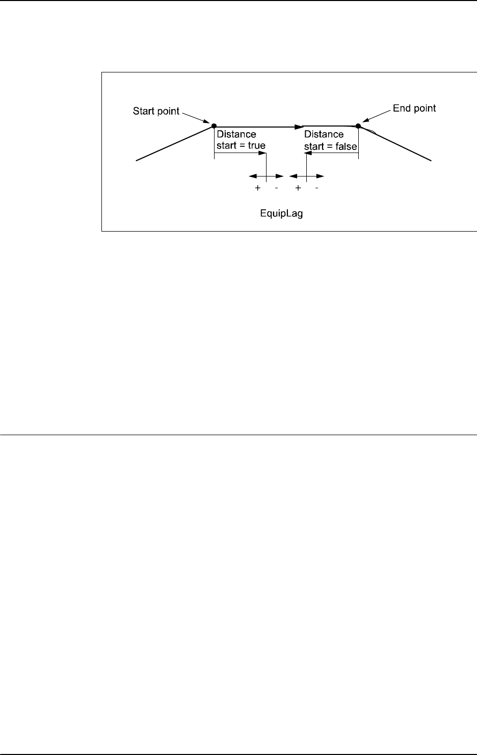
3 Data types
3.70. triggios - Positioning events, trigg
RobotWare - OS
12153HAC 16581-1 Revision: J
© Copyright 2004-2010 ABB. All rights reserved.
The figure shows use of component equiplag.
xx0800000173
signalname
Data type: string
The name of the signal that shall be changed. It have to be a digital output signal, group of
digital output signals or an analog output signal.
setvalue
Data type: num
Desired value of output signal (within the allowed range for the current signal).
xxx
Data type: num
Component is not used right now. Added to be able to add functionality in future releases, and
still be able to be compatible.
Examples
Example of the data type
triggios is illustrated below.
Example 1
VAR triggios gunon{1};
gunon{1}.used:=TRUE;
gunon{1}.distance:=3;
gunon{1}.start:=TRUE;
gunon{1}.signalname:="gun";
gunon{1}.equiplag:=0;
gunon{1}.setvalue:=1;
MoveJ p1, v500, z50, gun1;
TriggLIOs p2, v500, \TriggData1:=gunon, z50, gun1;
MoveL p3, v500, z50, gun1;
The signal gun is set when the TCP is 3 mm after point p1.
Continued
Continues on next page

3 Data types
3.70. triggios - Positioning events, trigg
RobotWare - OS
3HAC 16581-1 Revision: J1216
© Copyright 2004-2010 ABB. All rights reserved.
Structure
<dataobject of triggios>
<used of bool>
<distance of num>
<start of bool>
<equiplag of num>
<signalname of string>
<setvalue of num>
<xxx of num>
Related information
For information about See
Positioning events, trigg triggiosdnum - Positioning events, trigg on
page 1217
Linear robot movements with I/O events TriggLIOs - Linear robot movements with I/O
events on page 610
Continued

3 Data types
3.71. triggiosdnum - Positioning events, trigg
RobotWare - OS
12173HAC 16581-1 Revision: J
© Copyright 2004-2010 ABB. All rights reserved.
3.71. triggiosdnum - Positioning events, trigg
Usage
triggiosdnum is used to store data about a positioning event during a robot movement.
When the positioning event is distributed at a specific position on the path, an output signal
is set to a specified value.
Description
triggiosdnum is used to define conditions and actions for setting a digital output signal, a
group of digital output signals or an analog output signal at a fixed position along the robot’s
movement path.
Components
used
Data type: bool
Defines whether or not the array element should be used or not.
distance
Data type: num
Defines the position on the path where the I/O event shall occur. Specified as the distance in
mm (positive value) from the end point of the movement path if component
start is set to
FALSE.
start
Data type: bool
Set to TRUE when the distance starts at the movement start point instead of the end point.
equiplag
Equipment Lag
Data type:
num
Specifies the lag for the external equipment in s.
For compensation of external equipment lag, use a positive argument value. Positive value
means that the I/O signal is set by the robot system at a specified time before the TCP
physically reaches the specified distance in relation to the movement start or end point.
Negative value means that the I/O signal is set by the robot system at a specified time after
the TCP has physically passed the specified distance in relation to the movement start or end
point.
signalname
Data type: string
The name of the signal that shall be changed. It has to be a digital output signal, group of
digital output signals or an analog output signal.
setvalue
Data type: dnum
Desired value of output signal (within the allowed range for the current signal).
Continues on next page

3 Data types
3.71. triggiosdnum - Positioning events, trigg
RobotWare - OS
3HAC 16581-1 Revision: J1218
© Copyright 2004-2010 ABB. All rights reserved.
xxx
Data type: num
Component is not used right now. Added to be able to add functionality in future releases, and
still be able to be compatible.
Examples
Example of the data type
triggiosdnum is illustrated below.
Example 1
VAR triggiosdnum gunon{1};
gunon{1}.used:=TRUE;
gunon{1}.distance:=3;
gunon{1}.start:=TRUE;
gunon{1}.signalname:="go_gun";
gunon{1}.equiplag:=0;
gunon{1}.setvalue:=123456789;
MoveJ p1, v500, z50, gun1;
TriggLIOs p2, v500, \TriggData3:=gunon, z50, gun1;
MoveL p3, v500, z50, gun1;
The signal go_gun is set when the TCP is 3 mm after point p1.
Structure
<dataobject of triggiosdnum>
<used of bool>
<distance of num>
<start of bool>
<equiplag of num>
<signalname of string>
<setvalue of dnum>
<xxx of num>
Related information
For information about See
Positioning events, trigg triggios - Positioning events, trigg on page
1214
Linear robot movements with I/O events TriggLIOs - Linear robot movements with I/O
events on page 610
Continued

3 Data types
3.72. triggstrgo - Positioning events, trigg
RobotWare - OS
12193HAC 16581-1 Revision: J
© Copyright 2004-2010 ABB. All rights reserved.
3.72. triggstrgo - Positioning events, trigg
Usage
triggstrgo (trigg stringdig group output) is used to store data about a positioning event
during a robot movement. When the positioning event is distributed at a specific position on
the path, a group of digital output signals is set to a specified value.
Description
triggstrgo is used to define conditions and actions for setting a group of digital output
signals at a fixed position along the robot’s movement path.
Components
used
Data type: bool
Defines whether or not the array element should be used or not.
distance
Data type: num
Defines the position on the path where the I/O event shall occur. Specified as the distance in
mm (positive value) from the end point of the movement path if component
start is set to
FALSE.
start
Data type: bool
Set to TRUE when the distance starts at the movement start point instead of the end point.
equiplag
Equipment Lag
Data type:
num
Specify the lag for the external equipment in s.
For compensation of external equipment lag, use a positive argument value. Positive value
means that the I/O signal is set by the robot system at a specified time before the TCP
physically reaches the specified distance in relation to the movement start or end point.
Negative value means that the I/O signal is set by the robot system at a specified time after
that the TCP has physically passed the specified distance in relation to the movement start or
end point.
Continues on next page
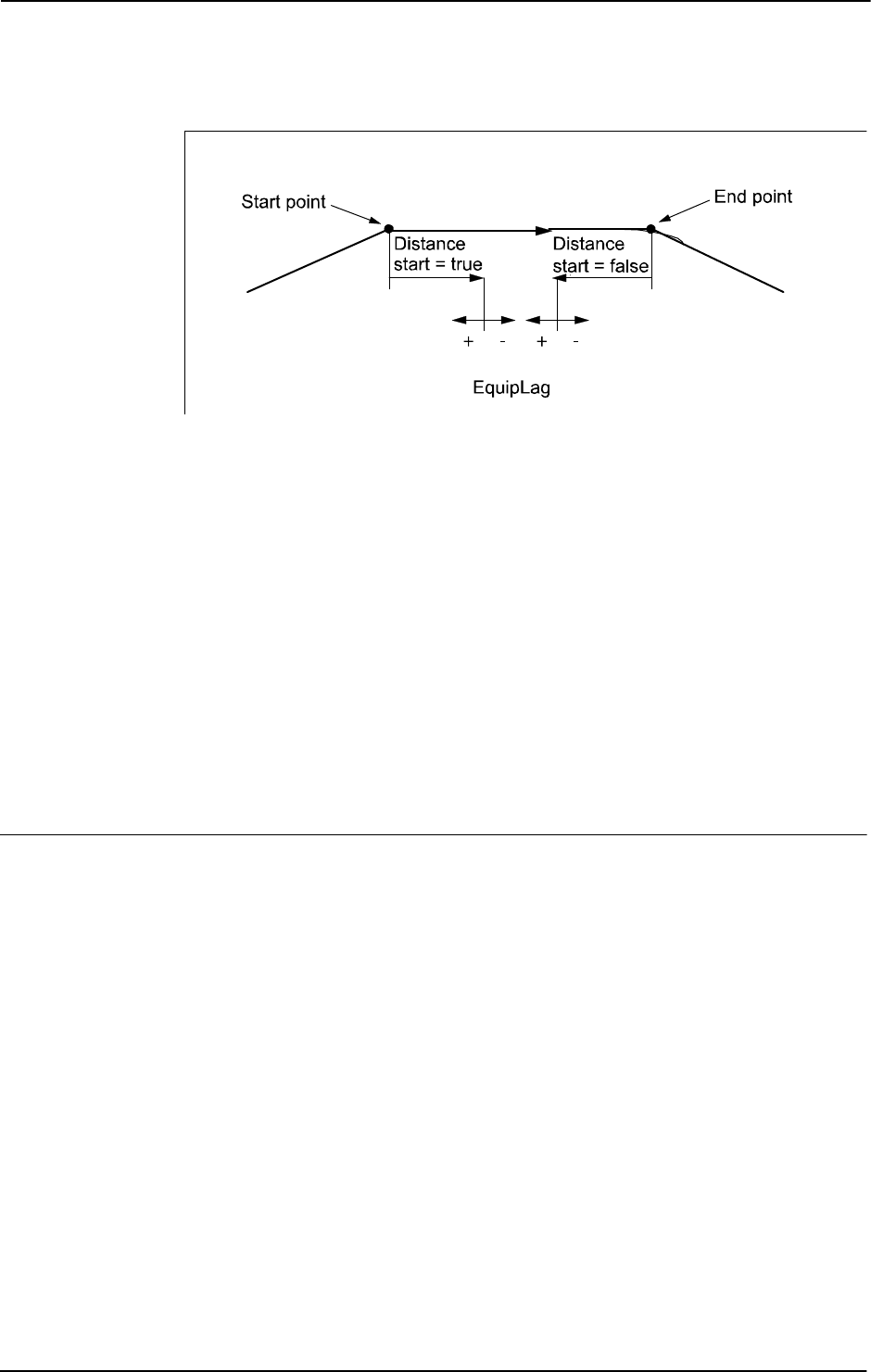
3 Data types
3.72. triggstrgo - Positioning events, trigg
RobotWare - OS
3HAC 16581-1 Revision: J1220
© Copyright 2004-2010 ABB. All rights reserved.
The figure shows use of component equiplag.
xx0800000173
signalname
Data type: string
The name of the signal that shall be changed. It has to be a name of a group output signal.
setvalue
Data type: stringdig
Desired value of output signal (within the allowed range for the current digital group output
signal). Using
stringdig data type makes it possible to use values up to 4294967295, which
is the maximum value a group of digital signals can have (32 signals in a group signal is max
for the system).
xxx
Data type: num
Component is not used right now. Added to be able to add functionality in future releases, and
still be able to be compatible.
Examples
Example of the data type
triggstrgo is illustrated below.
Example 1
VAR triggstrgo gunon{1};
gunon{1}.used:=TRUE;
gunon{1}.distance:=3;
gunon{1}.start:=TRUE;
gunon{1}.signalname:="gun";
gunon{1}.equiplag:=0;
gunon{1}.setvalue:="4294967295";
MoveJ p1, v500, z50, gun1;
TriggLIOs p2, v500, \TriggData2:=gunon, z50, gun1;
MoveL p3, v500, z50, gun1;
The signal gun is set to value 4294967295 when the TCP is 3 mm after point p1.
Continued
Continues on next page

3 Data types
3.72. triggstrgo - Positioning events, trigg
RobotWare - OS
12213HAC 16581-1 Revision: J
© Copyright 2004-2010 ABB. All rights reserved.
Structure
<dataobject of triggstrgo>
<used of bool>
<distance of num>
<start of bool>
<equiplag of num>
<signalname of string>
<setvalue of stringdig>
<xxx of num>
Related information
For information about See
Linear robot movements with I/O events TriggLIOs - Linear robot movements with I/O
events on page 610
Compare two strings with only digits StrDigCmp - Compare two strings with only
digits on page 991
Arithmetic operations on stringdig data types StrDigCalc - Arithmetic operations with
datatype stringdig on page 988
Continued

3 Data types
3.73. tunetype - Servo tune type
RobotWare - OS
3HAC 16581-1 Revision: J1222
© Copyright 2004-2010 ABB. All rights reserved.
3.73. tunetype - Servo tune type
Usage
tunetype is used to represent an integer with a symbolic constant for different types of servo
tuning.
Description
A tunetype constant is intended to be used as an argument to the instruction
TuneServo. See
example below.
Basic examples
Basic examples of the data type
tunetype are illustrated below.
Example 1
TuneServo MHA160R1, 1, 110 \Type:= TUNE_KP;
Predefined data
The following symbolic constants of the data type
tunetype are predefined and can be used
as arguments for the instruction
TuneServo.
Characteristics
tunetype is an alias data type for num and consequently inherits its characteristics.
Related information
Value Symbolic constant Comment
0 TUNE_DF Reduces overshoots
1 TUNE_KP Affects position control gain
2 TUNE_KV Affects speed control gain
3 TUNE_TI Affects speed control integration time
4 TUNE_FRIC_LEV Affects friction compensation level
5 TUNE_FRIC_RAMP Affects friction compensation ramp
6 TUNE_DG Reduces overshoots
7 TUNE_DH Reduces vibrations with heavy loads
8 TUNE_DI Reduces path errors
9 TUNE_DK Only for ABB internal use
10 TUNE_DL Only for ABB internal use
For information about See
Data types in general, alias data types Technical reference manual - RAPID overview,
section Basic characteristics - Data types
Use of data type tunetype TuneServo - Tuning servos on page 638

3 Data types
3.74. uishownum - Instance ID for UIShow
12233HAC 16581-1 Revision: J
© Copyright 2004-2010 ABB. All rights reserved.
3.74. uishownum - Instance ID for UIShow
Usage
uishownum is the data type used for parameter InstanceId in instruction UIShow. It is used
to identify a view on the FlexPendant.
Description
When a persistent variable of type
uishownum is used with the instruction UIShow, it is given
a specific value identifying the view launched on the FlexPendant. This persistent is then used
in all dealings with that view, such as launching the view again, modifying the view, etc.
Examples
Basic examples of the data type
uishownum are illustrated below.
Example 1
CONST string Name:="TpsViewMyAppl.gtpu.dll";
CONST string Type:="ABB.Robotics.SDK.Views.TpsViewMyAppl";
CONST string Cmd1:="Init data string passed to the view";
PERS uishownum myinstance:=0;
VAR num mystatus:=0;
...
! Launch one view of the application MyAppl
UIShow Name, Type \InitCmd:=Cmd1 \InstanceID:=myinstance
\Status:=mystatus;
The code above will launch one view of the application MyAppl with init command Cmd1.
The token used to identify the view is saved in the parameter
myinstance.
Characteristics
uishownum is an alias data type for num and thus inherits its properties.
Related information
For information about See
UIShow UIShow - User Interface show on page 651

3 Data types
3.75. wobjdata - Work object data
RobotWare - OS
3HAC 16581-1 Revision: J1224
© Copyright 2004-2010 ABB. All rights reserved.
3.75. wobjdata - Work object data
Usage
wobjdata is used to describe the work object that the robot welds, processes, moves within,
etc.
Description
If work objects are defined in a positioning instruction, the position will be based on the
coordinates of the work object. The advantages of this are as follows:
• If position data is entered manually, such as in off-line programming, the values can
often be taken from a drawing.
• Programs can be reused quickly following changes in the robot installation. If, for
example, the fixture is moved, only the user coordinate system has to be redefined.
• Variations in how the work object is attached can be compensated for. For this,
however, some sort of sensor will be required to position the work object.
If a stationary tool or coordinated external axes are used, the work object must be defined,
since the path and velocity would then be related to the work object instead of the TCP.
Work object data can also be used for jogging:
• The robot can be jogged in the directions of the work object.
• The current position displayed is based on the coordinate system of the work object.
Components
robhold
robot hold
Data type:
bool
Defines whether or not the robot in the actual program task is holding the work object:
• TRUE: The robot is holding the work object, i.e. using a stationary tool.
• FALSE: The robot is not holding the work object, i.e. the robot is holding the tool.
ufprog
user frame programmed
Data type:
bool
Defines whether or not a fixed user coordinate system is used:
• TRUE: Fixed user coordinate system.
• FALSE: Movable user coordinate system, i.e. coordinated external axes are used. Also
to be used in a MultiMove system in semicoordinated or synchronized coordinated
mode.
Continues on next page

3 Data types
3.75. wobjdata - Work object data
RobotWare - OS
12253HAC 16581-1 Revision: J
© Copyright 2004-2010 ABB. All rights reserved.
ufmec
user frame mechanical unit
Data type:
string
The mechanical unit with which the robot movements are coordinated. Only specified in the
case of movable user coordinate systems (
ufprog is FALSE).
Specify the mechanical unit name defined in system parameters, e.g.
orbit_a.
uframe
user frame
Data type:
pose
The user coordinate system, i.e. the position of the current work surface or fixture (see figure
below):
• The position of the origin of the coordinate system (x, y and z) in mm.
• The rotation of the coordinate system, expressed as a quaternion (q1, q2, q3, q4).
If the robot is holding the tool, the user coordinate system is defined in the world coordinate
system (in the wrist coordinate system if a stationary tool is used).
For movable user frame (
ufprog is FALSE), the user frame is continuously defined by the
system.
oframe
object frame
Data type:
pose
The object coordinate system, i.e. the position of the current work object (see figure below):
• The position of the origin of the coordinate system (x, y and z) in mm.
• The rotation of the coordinate system, expressed as a quaternion (q1, q2, q3, q4).
The object coordinate system is defined in the user coordinate system.
xx0500002369
Continued
Continues on next page

3 Data types
3.75. wobjdata - Work object data
RobotWare - OS
3HAC 16581-1 Revision: J1226
© Copyright 2004-2010 ABB. All rights reserved.
Basic examples
Basic examples of the data type
wobjdata are illustrated below.
Example 1
PERS wobjdata wobj2 :=[ FALSE, TRUE, "", [ [300, 600, 200], [1, 0,
0 ,0] ], [ [0, 200, 30], [1, 0, 0 ,0] ] ];
The work object in the figure above is described using the following values:
• The robot is not holding the work object.
• The fixed user coordinate system is used.
• The user coordinate system is not rotated and the coordinates of its origin are x= 300,
y =
600 and z = 200 mm in the world coordinate system.
• The object coordinate system is not rotated and the coordinates of its origin are x= 0,
y=
200 and z= 30 mm in the user coordinate system.
wobj2.oframe.trans.z := 38.3;
• The position of the work object wobj2 is adjusted to 38.3 mm in the z-direction.
Limitations
The work object data should be defined as a persistent variable (
PERS) and should not be
defined within a routine. The current values are then saved when the program is saved and
are retrieved on loading.
Arguments of the type work object data in any motion instruction should only be an entire
persistent (not array element or record component).
Predefined data
The work object data
wobj0 is defined in such a way that the object coordinate system
coincides with the world coordinate system. The robot does not hold the work object.
Wobj0 can always be accessed from the program, but can never be changed (it is stored in
system module BASE).
PERS wobjdata wobj0 := [ FALSE, TRUE, "", [ [0, 0, 0], [1, 0, 0
,0] ], [ [0, 0, 0], [1, 0, 0 ,0] ] ];
Structure
< dataobject of wobjdata >
< robhold of bool >
< ufprog of bool >
< ufmec of string >
< uframe of pose >
< trans of pos >
< x of num >
< y of num >
< z of num >
< rot of orient >
< q1 of num >
< q2 of num >
< q3 of num >
< q4 of num >
Continued
Continues on next page

3 Data types
3.75. wobjdata - Work object data
RobotWare - OS
12273HAC 16581-1 Revision: J
© Copyright 2004-2010 ABB. All rights reserved.
< oframe of pose >
< trans of pos >
< x of num >
< y of num >
< z of num >
< rot of orient >
< q1 of num >
< q2 of num >
< q3 of num >
< q4 of num >
Related information
For information about See
Positioning instructions Technical reference manual - RAPID overview,
section RAPID summary - Motion
Coordinate systems Technical reference manual - RAPID overview,
section Motion and I/O Principles - Coordinate
systems
Coordinated external axes Technical reference manual - RAPID overview,
section Motion and I/O Principles - Coordinate
systems
Calibration of coordinated axes Application manual - Additional axes and stand
alone controller
Application manual - MultiMove
Continued

3 Data types
3.76. wzstationary - Stationary world zone data
World Zones
3HAC 16581-1 Revision: J1228
© Copyright 2004-2010 ABB. All rights reserved.
3.76. wzstationary - Stationary world zone data
Usage
wzstationary (world zone stationary) is used to identify a stationary world zone and can
only be used in an event routine connected to the event POWER ON.
A world zone is supervised during robot movements both during program execution and
jogging. If the robot’s TCP reaches the world zone or if the robot/external axes reaches the
world zone in joints, the movement is stopped or a digital output signal is set or reset.
Description
A
wzstationary world zone is defined and activated by a WZLimSup or a WZDOSet
instruction.
WZLimSup or WZDOSet gives the variable or the persistent of data type wzstationary a
numeric value. The value identifies the world zone.
A stationary world zone is always active in motor on state and is only erased by a warm start
(switch power off then on). It is not possible to deactivate, activate or erase a stationary world
zone via RAPID instructions.
Stationary world zones should be active from power on and should be defined in a POWER
ON event routine or a semistatic task
Basic examples
Basic examples of the data type
wzstationary are illustrated below.
Example 1
VAR wzstationary conveyor;
...
PROC ...
VAR shapedata volume;
...
WZBoxDef \Inside, volume, p_corner1, p_corner2;
WZLimSup \Stat, conveyor, volume;
ENDPROC
A conveyor is defined as a straight box (the volume below the belt). If the robot reaches this
volume, the movement is stopped.
Limitations
A
wzstationary data can be defined as a variable (VAR) or as a persistent (PERS). It can
be global in task or local within module, but not local within a routine.
Arguments of the type
wzstationary should only be entire data (not array element or record
component).
An init value for data of the type
wzstationary is not used by the control system. When
there is a need to use a persistent variable in a multi-tasking system, set the init value to 0 in
both tasks, e.g.
PERS wzstationary share_workarea := [0];
More examples
For a complete example see instruction
WZLimSup.
Continues on next page

3 Data types
3.76. wzstationary - Stationary world zone data
World Zones
12293HAC 16581-1 Revision: J
© Copyright 2004-2010 ABB. All rights reserved.
Characteristics
wzstationary is an alias data type of wztemporary and inherits its characteristics.
Related information
For information about See
World Zones Technical reference manual - RAPID overview,
section Motion and I/O principles - World zones
World zone shape shapedata - World zone shape data on page 1179
Temporary world zone wztemporary - Temporary world zone data on
page 1230
Activate world zone limit supervision WZLimSup - Activate world zone limit supervision
on page 753
Activate world zone digital output set WZDOSet - Activate world zone to set digital
output on page 738
Continued

3 Data types
3.77. wztemporary - Temporary world zone data
RobotWare - OS
3HAC 16581-1 Revision: J1230
© Copyright 2004-2010 ABB. All rights reserved.
3.77. wztemporary - Temporary world zone data
Usage
wztemporary (world zone temporary) is used to identify a temporary world zone and can be
used anywhere in the RAPID program for any motion task.
A world zone is supervised during robot movements both during program execution and
jogging. If the robot’s TCP reaches the world zone or if the robot/external axes reaches the
world zone in joints, the movement is stopped or a digital output signal is set or reset.
Description
A
wztemporary world zone is defined and activated by a WZLimSup or a WZDOSet
instruction.
WZLimSup or WZDOSet gives the variable or the persistent of data type wztemporary a
numeric value. The value identifies the world zone.
Once defined and activated, a temporary world zone can be deactivated by
WZDisable,
activated again by
WZEnable, and erased by WZFree.
All temporary world zones in the motion task are automatically erased and all data objects of
type
wztemporary in the motion task are set to 0:
• when a new program is loaded in the motion task
• when starting program execution from the beginning in the motion task
Basic examples
Basic examples of the data type
wztemporary are illustrated below.
Example 1
VAR wztemporary roll;
...
PROC
VAR shapedata volume;
CONST pos t_center := [1000, 1000, 1000];
...
WZCylDef \Inside, volume, t_center, 400, 1000;
WZLimSup \Temp, roll, volume;
ENDPROC
A wztemporary variable, roll, is defined as a cylinder. If the robot reaches this volume,
the movement is stopped.
Continues on next page

3 Data types
3.77. wztemporary - Temporary world zone data
RobotWare - OS
12313HAC 16581-1 Revision: J
© Copyright 2004-2010 ABB. All rights reserved.
Limitations
A
wztemporary data can be defined as a variable (VAR) or as a persistent (PERS). It can be
global in a task or local within a module, but not local within a routine.
Arguments of the type
wztemporary must only be entire data, not an array element or record
component.
A temporary world zone must only be defined (
WZLimSup or WZDOSet) and free (WZFree)
in the motion task. Definitions of temporary world zones in any background is not allowed
because it would affect the program execution in the connected motion task. The instructions
WZDisable and WZEnable can be used in the background task. When there is a need to use
a persistent variable in a multi-tasking system, set the init value to 0 in both tasks, e.g. PERS
wztemporary share_workarea := [0];
More examples
For a complete example see instruction
WZDOSet.
Structure
< dataobject of wztemporary >
< wz of num >
Related information
For information about See
World Zones Technical reference manual - RAPID overview,
section Motion and I/O principles - World zones
World zone shape shapedata - World zone shape data on page 1179
Stationary world zone wzstationary - Stationary world zone data on page
1228
Activate world zone limit supervision WZLimSup - Activate world zone limit supervision
on page 753
Activate world zone digital output set WZDOSet - Activate world zone to set digital output
on page 738
Deactivate world zone WZDisable - Deactivate temporary world zone
supervision on page 736
Activate world zone WZEnable - Activate temporary world zone
supervision on page 742
Erase world zone WZFree - Erase temporary world zone supervision
on page 744
Continued
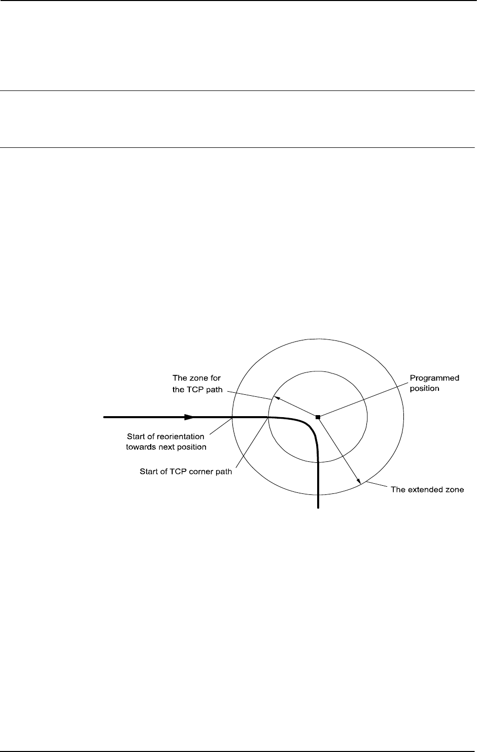
3 Data types
3.78. zonedata - Zone data
RobotWare - OS
3HAC 16581-1 Revision: J1232
© Copyright 2004-2010 ABB. All rights reserved.
3.78. zonedata - Zone data
Usage
zonedata is used to specify how a position is to be terminated, i.e. how close to the
programmed position the axes must be before moving towards the next position.
Description
A position can be terminated either in the form of a stop point or a fly-by point.
A stop point means that the robot and external axes must reach the specified position (stand
still) before program execution continues with the next instruction. It is also possible to define
stop points other than the predefined
fine. The stop criteria, that tells if the robot is
considered to have reached the point, can be manipulated using the
stoppointdata.
A fly-by point means that the programmed position is never attained. Instead, the direction of
motion is changed before the position is reached. Two different zones (ranges) can be defined
for each position:
• The zone for the TCP path.
• The extended zone for reorientation of the tool and for external axes.
xx0500002357
Zones function is the same during joint movement, but the zone size may differ somewhat
from the one programmed.
The zone size cannot be larger than half the distance to the closest position (forwards or
backwards). If a larger zone is specified, the robot automatically reduces it.
The zone for the TCP path
A corner path (parabola) is generated as soon as the edge of the zone is reached (see figure
above).
Continues on next page
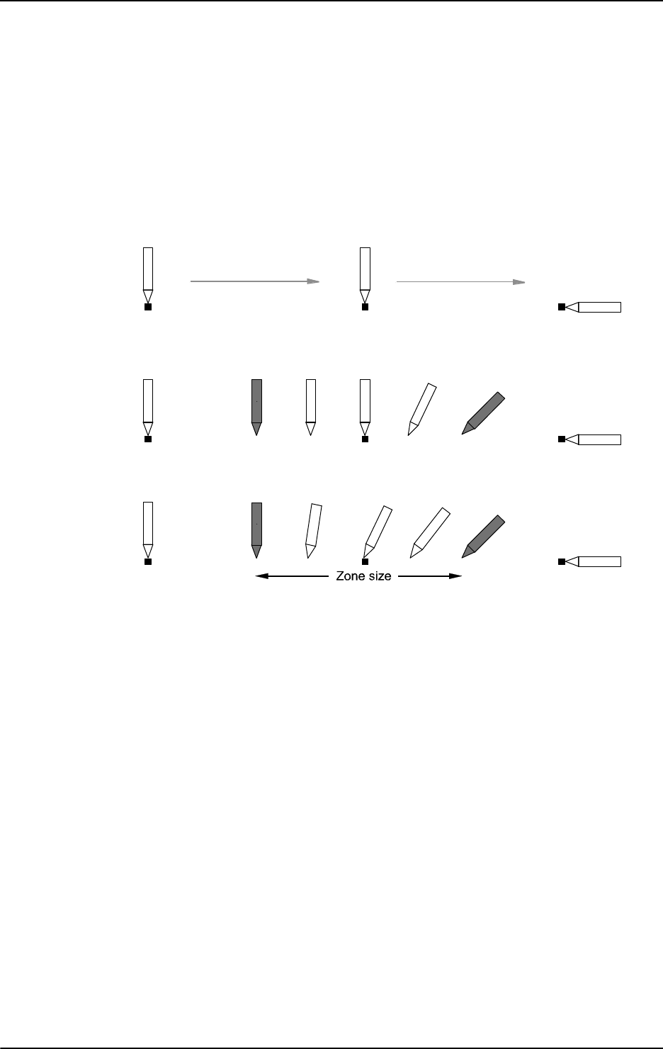
3 Data types
3.78. zonedata - Zone data
RobotWare - OS
12333HAC 16581-1 Revision: J
© Copyright 2004-2010 ABB. All rights reserved.
The zone for reorientation of the tool
Reorientation starts as soon as the TCP reaches the extended zone. The tool is reoriented in
such a way that the orientation is the same leaving the zone as it would have been in the same
position if stop points had been programmed. Reorientation will be smoother if the zone size
is increased, and there is less of a risk of having to reduce the velocity to carry out the
reorientation.
The following figure shows three programmed positions, the last with different tool
orientation.
xx0500002358
The following figure shows what program execution would look like if all positions were stop
points.
xx0500002359
The following figure shows what program execution would look like if the middle position
was a fly-by point.
xx0500002360
The zone for external axes
External axes start to move towards the next position as soon as the TCP reaches the extended
zone. In this way, a slow axis can start accelerating at an earlier stage and thus execute more
smoothly.
Continued
Continues on next page
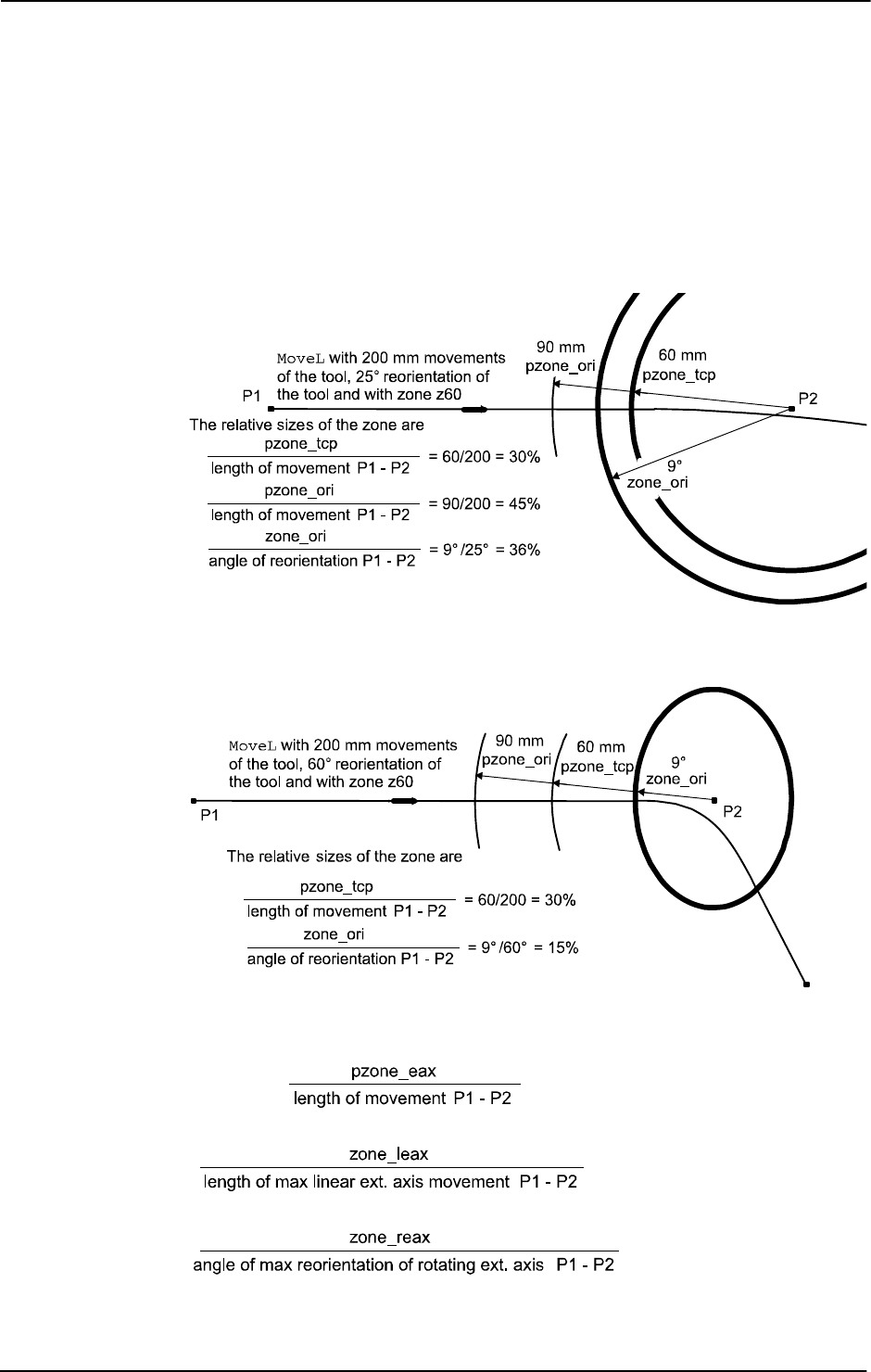
3 Data types
3.78. zonedata - Zone data
RobotWare - OS
3HAC 16581-1 Revision: J1234
© Copyright 2004-2010 ABB. All rights reserved.
Reduced zone
With large reorientations of the tool or with large movements of the external axes, the
extended zone and even the TCP zone can be reduced by the robot. The zone will be defined
as the smallest relative size of the zone based upon the zone components (see Components on
page 1235) and the programmed motion.
The following figure shows an example of reduced zone for reorientation of the tool to 36%
of the motion due to zone_ori.
xx0500002362
The following figure shows an example of reduced zone for reorientation of the tool and TCP
path to 15% of the motion due to zone_ori.
xx0500002363
When external axes are active they affect the relative sizes of the zone according to these
formulas:
xx0500002364
Continued
Continues on next page

3 Data types
3.78. zonedata - Zone data
RobotWare - OS
12353HAC 16581-1 Revision: J
© Copyright 2004-2010 ABB. All rights reserved.
NOTE!
If the TCP zone is reduced because of
zone_ori, zone_leax or zone_reax, the path
planner enters a mode that can handle the case of no TCP movement. If there is a TCP
movement when in this mode, the speed is not compensated for the curvature of the path in a
corner zone. For instance, this will cause a 30% speed reduction in a 90 degree corner. If this
is a problem, increase the limiting zone component.
Components
finep
fine point
Data type:
bool
Defines whether the movement is to terminate as a stop point (fine point) or as a fly-by
point.
• TRUE: The movement terminates as a stop point, and the program execution will not
continue until robot reach the stop point. The remaining components in the zone data
are not used.
• FALSE: The movement terminates as a fly-by point, and the program execution
continues about 100 ms before the robot reaches the zone.
pzone_tcp
path zone TCP
Data type:
num
The size (the radius) of the TCP zone in mm.
The extended zone will be defined as the smallest relative size of the zone based upon the
following components
pzone_ori...zone_reax and the programmed motion.
pzone_ori
path zone orientation
Data type:
num
The zone size (the radius) for the tool reorientation. The size is defined as the distance of the
TCP from the programmed point in mm.
The size must be larger than the corresponding value for
pzone_tcp. If a lower value is
specified, the size is automatically increased to make it the same as
pzone_tcp.
pzone_eax
path zone external axes
Data type:
num
The zone size (the radius) for external axes. The size is defined as the distance of the TCP
from the programmed point in mm.
The size must be larger than the corresponding value for
pzone_tcp. If a lower value is
specified, the size is automatically increased to make it the same as
pzone_tcp.
Continued
Continues on next page

3 Data types
3.78. zonedata - Zone data
RobotWare - OS
3HAC 16581-1 Revision: J1236
© Copyright 2004-2010 ABB. All rights reserved.
zone_ori
zone orientation
Data type:
num
The zone size for the tool reorientation in degrees. If the robot is holding the work object, this
means an angle of rotation for the work object.
zone_leax
zone linear external axes
Data type:
num
The zone size for linear external axes in mm.
zone_reax
zone rotational external axes
Data type:
num
The zone size for rotating external axes in degrees.
Basic examples
Basic examples of the data type
zonedata are illustrated below.
Example 1
VAR zonedata path := [ FALSE, 25, 40, 40, 10, 35, 5 ];
The zone data path is defined by means of the following characteristics:
• The zone size for the TCP path is 25 mm.
• The zone size for the tool reorientation is 40 mm (TCP movement).
• The zone size for external axes is 40 mm (TCP movement).
If the TCP is standing still, or there is a large reorientation, or there is a large external axis
movement with respect to the zone, the following apply instead:
• The zone size for the tool reorientation is 10 degrees.
• The zone size for linear external axes is 35 mm.
• The zone size for rotating external axes is 5 degrees.
path.pzone_tcp := 40;
The zone size for the TCP path is adjusted to 40 mm.
Predefined data
A number of zone data are already defined in the system module
BASE_SHARED.
Stop points
Use zonedata named fine.
Fly-by points
Path zone Zone
Name TCP path Orientation Ext. axis Orientation
Linear
axis
Rotating
axis
z0 0.3 mm 0.3 mm 0.3 mm 0.03° 0.3 mm 0.03°
z1 1 mm 1 mm 1 mm 0.1° 1 mm 0.1°
z5 5 mm 8 mm 8 mm 0.8° 8 mm 0.8°
Continued
Continues on next page

3 Data types
3.78. zonedata - Zone data
RobotWare - OS
12373HAC 16581-1 Revision: J
© Copyright 2004-2010 ABB. All rights reserved.
Structure
< data object of zonedata >
< finep of bool >
< pzone_tcp of num >
< pzone_ori of num >
< pzone_eax of num >
< zone_ori of num >
< zone_leax of num >
< zone_reax of num >
Related information
z10 10 mm 15 mm 15 mm 1.5° 15 mm 1.5°
z15 15 mm 23 mm 23 mm 2.3° 23 mm 2.3°
z20 20 mm 30 mm 30 mm 3.0° 30 mm 3.0°
z30 30 mm 45 mm 45 mm 4.5° 45 mm 4.5°
z40 40 mm 60 mm 60 mm 6.0° 60 mm 6.0°
z50 50 mm 75 mm 75 mm 7.5° 75 mm 7.5°
z60 60 mm 90 mm 90 mm 9.0° 90 mm 9.0°
z80 80 mm 120 mm 120 mm 12° 120 mm 12°
z100 100 mm 150 mm 150 mm 15° 150 mm 15°
z150 150 mm 225 mm 225 mm 23° 225 mm 23°
z200 200 mm 300 mm 300 mm 30° 300 mm 30°
Path zone Zone
Name TCP path Orientation Ext. axis Orientation
Linear
axis
Rotating
axis
For information about See
Positioning instructions Technical reference manual - RAPID overview,
section RAPID summary - Motion
Movements/Paths in general Technical reference manual - RAPID overview,
section Motion and I/O principles - Positioning during
program execution
Configuration of external axes Application manual - Additional axes and stand
alone controller
Other Stop points stoppointdata - Stop point data on page 1189
Continued

3 Data types
3.78. zonedata - Zone data
RobotWare - OS
3HAC 16581-1 Revision: J1238
© Copyright 2004-2010 ABB. All rights reserved.

4 Programming type examples
4.1. ERROR handler with movements
Path Recovery
12393HAC 16581-1 Revision: J
© Copyright 2004-2010 ABB. All rights reserved.
4 Programming type examples
4.1. ERROR handler with movements
Usage
These type examples describe how to use move instructions in an ERROR handler after an
asynchronously raised process or movement error has occurred.
This functionality can only be used in the main task
T_ROB1 or, if in a MultiMove system, in
Motion tasks.
Description
The
ERROR handler can start a new temporary movement and finally restart the original
interrupted and stopped movement. For example, it can be used to go to a service position or
to clean the gun after an asynchronously raised process or movement error has occurred.
To reach this functionality, the instructions
StorePath - RestoPath must be used in the
ERROR handler. To restart the movement and continue the program execution, several RAPID
instructions are available.
Type examples
Type examples of the functionality are illustrated below.
Principle
...
ERROR
IF ERRNO = ERR_PATH_STOP THEN
StorePath;
! Move away and back to the interrupted position
...
RestoPath;
StartMoveRetry;
ENDIF
ENDPROC
At execution of StartMoveRetry the robot resumes its movement, any active process is
restarted and the program retries its execution.
StartMoveRetry does the same as
StartMove plus RETRY in one indivisible operation.
Continues on next page

4 Programming type examples
4.1. ERROR handler with movements
Path Recovery
3HAC 16581-1 Revision: J1240
© Copyright 2004-2010 ABB. All rights reserved.
Automatic restart of execution
CONST robtarget service_pos := [...];
VAR robtarget stop_pos;
...
ERROR
IF ERRNO = AW_WELD_ERR THEN
! Current movement on motion base path level
! is already stopped.
! New motion path level for new movements in the ERROR handler
StorePath;
! Store current position from motion base path level
stop_pos := CRobT(\Tool:=tool1, \WObj:=wobj1);
! Do the work to fix the problem
MoveJ service_pos, v50, fine, tool1, \WObj:=wobj1;
...
! Move back to the position on the motion base path level
MoveJ stop_pos, v50, fine, tool1, \WObj:=wobj1;
! Go back to motion base path level
RestoPath;
! Restart the stopped movements on motion base path level,
! restart the process and retry program execution
StartMoveRetry;
ENDIF
ENDPROC
This is a type example of how to use automatic asynchronously error recovery after some type
of process error during robot movements.
Manual restart of execution
...
ERROR
IF ERRNO = PROC_ERR_XXX THEN
! Current movement on motion base path level
! is already stopped and in stop move state.
! This error must be handle manually.
! Reset the stop move state on motion base path level.
StopMoveReset;
ENDIF
ENDPROC
This is a type example of how to use manual handling of asynchronously error recovery after
some type of process error during robot movements.
After the above
ERROR handler has executed to the end, the program execution stops and the
program pointer is at the beginning of the instruction with the process error (also at beginning
of any used NOSTEPIN routine). The next program start restarts the program and movement
from the position in which the original process error ocurred.
Continued
Continues on next page

4 Programming type examples
4.1. ERROR handler with movements
Path Recovery
12413HAC 16581-1 Revision: J
© Copyright 2004-2010 ABB. All rights reserved.
Program execution
Execution behavior:
• At start execution of the ERROR handler, the program leaves its base execution level
• At execution of StorePath, the motion system leaves its base execution level
• At execution of RestoPath, the motion system returns to its base execution level
• At execution of StartMoveRetry, the program returns to its base execution level
Limitations
The following
RAPID instructions must be used in the ERROR handler with move instructions
to get it working for automatically error recovery after an asynchronously raised process or
path error:
The following
RAPID instruction must be used in the ERROR handler to get it working for
manually error recovery after an asynchronously raised process or path error:
Related information
Instruction Description
StorePath Enter new motion path level
RestoPath Return to motion base path level
StartMoveRetry Restart the interrupted movements on the motion base path
level. Also restart the process and retry the program execution.
Same functionality as StartMove + RETRY.
Instruction Description
StopMoveReset Enter new motion path level
For information about See
To enter a new motion path level StorePath - Stores the path when an interrupt
occurs on page 521
To return to motion base path level RestoPath - Restores the path after an
interrupt on page 362
To restart the interrupted movement, process
and retry program execution.
StartMoveRetry - Restarts robot movement
and execution on page 489
Continued

4 Programming type examples
4.2. Service routines with or without movements
Path recovery
3HAC 16581-1 Revision: J1242
© Copyright 2004-2010 ABB. All rights reserved.
4.2. Service routines with or without movements
Usage
These type examples describe how to use move instructions in a service routine. Same
principle about
StopMove, StartMove and StopMoveReset are also valid for service
routines without movements (only logical instructions).
Both service routines or other routines (procedures) without parameters can be started
manually and perform movements according to these type examples.
This functionality can only be used in the main task
T_ROB1 or, if in a MultiMove system, in
Motion tasks in independent or semi-coordinated mode.
Description
The service routine can start a new temporary movement and, at later program start, restart
the original movement. For example, it can be used to go to a service position or manually
start cleaning the gun.
To reach this functionality the instructions
StorePath - RestoPath and StopMoveReset
must be used in the service routine.
Type examples
Type examples of the functionality are illustrated below.
Principle
PROC xxxx()
StopMove;
StorePath;
! Move away and back to the interrupted position
...
RestoPath;
StopMoveReset;
ENDPROC
StopMove
is required in order to make sure that the originally stopped movement is not
restarted upon a manually "stop program-restart program" sequence during execution of the
service routine.
Continues on next page

4 Programming type examples
4.2. Service routines with or without movements
Path recovery
12433HAC 16581-1 Revision: J
© Copyright 2004-2010 ABB. All rights reserved.
Stop on path
VAR robtarget service_pos := [...];
...
PROC proc_stop_on_path()
VAR robtarget stop_pos;
! Current stopped movements on motion base path level
! must not be restarted in the service routine.
StopMove;
! New motion path level for new movements in the service routine.
StorePath;
! Store current position from motion base path level
stop_pos := CRobT(\Tool:=tool1 \WObj:=wobj1);
! Do the work
MoveJ service_pos, v50, fine, tool1 \WObj:=wobj1;
...
! Move back to interrupted position on the motion base path level
MoveJ stop_pos, v50, fine, tool1, \WObj:=wobj1;
! Go back to motion base path level
RestoPath;
! Reset the stop move state for the interrupted movement
! on motion base path level
StopMoveReset;
ENDPROC
In this type example the movements in the service routine start and end at the position on the
path where the program was stopped.
Also note that the tool and work object used are known at the time of programming.
Continued
Continues on next page

4 Programming type examples
4.2. Service routines with or without movements
Path recovery
3HAC 16581-1 Revision: J1244
© Copyright 2004-2010 ABB. All rights reserved.
Stop in next stop point
TASK PERS tooldata used_tool := [...];
TASK PERS wobjdata used_wobj := [...];
...
PROC proc_stop_in_stop_point()
VAR robtarget stop_pos;
! Current move instruction on motion base path level continue
! to it’s ToPoint and will be finished in a stop point.
StartMove;
! New motion path level for new movements in the service routine
StorePath;
! Get current tool and work object data
GetSysData used_tool;
GetSysData used_wobj;
! Store current position from motion base path level
stop_pos := CRobT(\Tool:=used_tool \WObj:=used_wobj);
! Do the work
MoveJ Offs(stop_pos,0,0,20),v50,fine,used_tool\WObj:=used_wobj;
...
! Move back to interrupted position on the motion base path level
MoveJ stop_pos, v50, fine, used_tool,\WObj:=used_wobj;
! Go back to motion base path level
RestoPath;
! Reset the stop move state for any new movement
! on motion base path level
StopMoveReset;
ENDPROC
In this type example the movements in the service routine continue to and end at the ToPoint
in the interrupted move instructions before the instruction
StorePath is ready.
Also note that the tool and work object used are unknown at the time of programming.
Program execution
Execution behavior:
• At start execution of the service routine, the program leaves its base execution level
• At execution of StorePath, the motion system leaves its base execution level
• At execution of RestoPath, the motion system returns to its base execution level
• At execution of ENDPROC, the program returns to its base execution level
Continued
Continues on next page

4 Programming type examples
4.2. Service routines with or without movements
Path recovery
12453HAC 16581-1 Revision: J
© Copyright 2004-2010 ABB. All rights reserved.
Limitations
The following
RAPID instructions must be used in the service routine with move instructions
to get it working:
Related information
Instruction Description
StorePath Enter new motion path level
RestoPath Return to motion base path level
StopMoveReset Reset the stop move state for the interrupted
movement on the motion base path level
For information about See
No restart of the already stopped movement
on the motion base path level
StopMove - Stops robot movement on page
515
Restart of the already stopped movement on
the motion base path level
StopMove - Stops robot movement on page
515
To enter a new motion path level StorePath - Stores the path when an interrupt
occurs on page 521
To return to the motion base path level RestoPath - Restores the path after an
interrupt on page 362
Reset the stop move state for the interrupted
movement on the motion base path level
StopMoveReset - Reset the system stop
move state on page 519
Continued

4 Programming type examples
4.3. System I/O interrupts with or without movements
Path recovery
3HAC 16581-1 Revision: J1246
© Copyright 2004-2010 ABB. All rights reserved.
4.3. System I/O interrupts with or without movements
Usage
These type examples describe how to use move instructions in a system I/O interrupt routine.
Same principle about
StopMove, StartMove and StopMoveReset are also valid for
system I/O interrupts without movements (only logical instructions).
This functionality can only be used in the main task
T_ROB1 or, if in a MultiMove system, in
Motion tasks in independent or semi-coordinated mode.
Description
The system I/O interrupt routine can start a new temporary movement and, at later program
start, restart the original movement. For example, it can be used to go to a service position or
to clean the gun when an interrupt occurs.
To reach this functionality the instructions
StorePath - RestoPath and StopMoveReset
must be used in the system I/O interrupt routine.
Type examples
Type examples of the functionality are illustrated below.
Principle
PROC xxxx()
StopMove;
StorePath;
! Move away and back to the interrupted position
...
RestoPath;
StopMoveReset;
ENDPROC
StopMove
is required in order to make sure that the originally stopped movement is not
restarted at start of the I/O interrupt routine.
Without
StopMove or with StartMove instead the movement in the I/O interrupt routine
will continue at once and end at the
ToPoint in the interrupted move instruction.
Continues on next page

4 Programming type examples
4.3. System I/O interrupts with or without movements
Path recovery
12473HAC 16581-1 Revision: J
© Copyright 2004-2010 ABB. All rights reserved.
Stop on path
VAR robtarget service_pos := [...];
...
PROC proc_stop_on_path()
VAR robtarget stop_pos;
! Current stopped movements on motion base path level
! isn’t restarted in the system I/O routine.
StopMove \Quick;
! New motion path level for new movements in the system
! I/O routine.
StorePath;
! Store current position from motion base path level
stop_pos := CRobT(\Tool:=tool1 \WObj:=wobj1);
! Do the work
MoveJ service_pos, v50, fine, tool1 \WObj:=wobj1;
...
! Move back to interrupted position on the motion base path level
MoveJ stop_pos, v50, fine, tool1, \WObj:=wobj1;
! Go back to motion base path level
RestoPath;
! Reset the stop move state for the interrupted movement
! on motion base path level
StopMoveReset;
ENDPROC
In this type example the interrupted movements are stopped at once and are restarted at
program start after the system I/O interrupt routine is finished.
Also note that the tool and work object used are known at the time of programming.
Continued
Continues on next page

4 Programming type examples
4.3. System I/O interrupts with or without movements
Path recovery
3HAC 16581-1 Revision: J1248
© Copyright 2004-2010 ABB. All rights reserved.
Stop in next stop point
TASK PERS tooldata used_tool := [...];
TASK PERS wobjdata used_wobj := [...];
...
PROC proc_stop_in_stop_point()
VAR robtarget stop_pos;
! Current move instruction on motion base path level continue
! to it’s ToPoint and will be finished in a stop point.
StartMove;
! New motion path level for new movements in the system
! I/O routine
StorePath;
! Get current tool and work object data
GetSysData used_tool;
GetSysData used_wobj;
! Store current position from motion base path level
stop_pos := CRobT(\Tool:=used_tool \WObj:=used_wobj);
! Do the work
MoveJ Offs(stop_pos,0,0,20),v50,fine,used_tool\WObj:=used_wobj;
...
! Move back to interrupted position on the motion base path level
MoveJ stop_pos, v50, fine, used_tool,\WObj:=used_wobj;
! Go back to motion base path level
RestoPath;
! Reset the stop move state for new movement
! on motion base path level
StopMoveReset;
ENDPROC
In this type example the movements in the system I/O routine continue at once, and end at the
ToPoint in the interrupted move instructions.
Also note that the tool and work object used are unknown at the time of programming.
Program execution
Execution behavior:
• At start execution of the system I/O routine, the program leaves its base execution
level
• At execution of StorePath, the motion system leaves its base execution level
• At execution of RestoPath, the motion system returns to its base execution level
• At execution of ENDPROC, the program returns to its base execution level
Continued
Continues on next page

4 Programming type examples
4.3. System I/O interrupts with or without movements
Path recovery
12493HAC 16581-1 Revision: J
© Copyright 2004-2010 ABB. All rights reserved.
Limitations
The following
RAPID instructions must be used in the system IO routine with move
instructions to get it working:
Related information
Instruction Description
StorePath Enter new motion path level
RestoPath Return to motion base path level
StopMoveReset Reset the stop move state for the interrupted movement on the
motion base path level
For information about See
No restart of the already stopped movement
on the motion base path level
StopMove - Stops robot movement on page
515
Restart of the already stopped movement on
the motion base path level
StartMove - Restarts robot movement on
page 486
To enter a new motion path level StorePath - Stores the path when an interrupt
occurs on page 521
To return to the motion base path level RestoPath - Restores the path after an
interrupt on page 362
Reset the stop move state for the interrupted
movement on the motion base path level
StopMoveReset - Reset the system stop
move state on page 519
Continued

4 Programming type examples
4.4. TRAP routines with movements
Path Recovery
3HAC 16581-1 Revision: J1250
© Copyright 2004-2010 ABB. All rights reserved.
4.4. TRAP routines with movements
Usage
These type examples describe how to use move instructions in a
TRAP routine after an
interrupt has occurred.
This functionality can only be used in the main task
T_ROB1 or, if in a MultiMove system, in
Motion tasks.
Description
The
TRAP routine can start a new temporary movement and finally restart the original
movement. For example, it can be used to go to a service position or to clean the gun when
an interrupt occurs.
To reach this functionality the instructions
StorePath - RestoPath and StartMove must
be used in the
TRAP routine.
Type examples
Type examples of the functionality are illustrated below.
Principle
TRAP xxxx
StopMove;
StorePath;
! Move away and back to the interrupted position
...
RestoPath;
StartMove;
ENDTRAP
If StopMove is used, the movement stops at once on the on-going path; otherwise, the
movement continues to the
ToPoint in the actual move instruction.
Continues on next page

4 Programming type examples
4.4. TRAP routines with movements
Path Recovery
12513HAC 16581-1 Revision: J
© Copyright 2004-2010 ABB. All rights reserved.
Stop in next stop point
VAR robtarget service_pos := [...];
...
TRAP trap_in_stop_point
VAR robtarget stop_pos;
! Current move instruction on motion base path level continue
! to it’s ToPoint and will be finished in a stop point.
! New motion path level for new movements in the TRAP
StorePath;
! Store current position from motion base path level
stop_pos := CRobT(\Tool:=tool1 \WObj:=wobj1);
! Do the work
MoveJ service_pos, v50, fine, tool1 \WObj:=wobj1;
...
! Move back to interrupted position on the motion base path level
MoveJ stop_pos, v50, fine, tool1, \WObj:=wobj1;
! Go back to motion base path level
RestoPath;
! Restart the interupted movements on motion base path level
StartMove;
ENDTRAP
In this type example the movements in the TRAP routine start and end at the ToPoint in the
interrupted move instructions. Also note that the tool and work object are known at the time
of programming.
Continued
Continues on next page

4 Programming type examples
4.4. TRAP routines with movements
Path Recovery
3HAC 16581-1 Revision: J1252
© Copyright 2004-2010 ABB. All rights reserved.
Stop on path at once
TASK PERS tooldata used_tool := [...];
TASK PERS wobjdata used_wobj := [...];
...
TRAP trap_stop_at_once
VAR robtarget stop_pos;
! Current move instruction on motion base path level stops
! at once
StopMove;
! New motion path level for new movements in the TRAP
StorePath;
! Get current tool and work object data
GetSysData used_tool;
GetSysData used_wobj;
! Store current position from motion base path level
stop_pos := CRobT(\Tool:=used_tool \WObj:=used_wobj);
! Do the work
MoveJ Offs(stop_pos,0,0,20),v50,fine,used_tool\WObj:=used_wobj;
...
! Move back to interrupted position on the motion base path level
MoveJ stop_pos, v50, fine, used_tool,\WObj:=used_wobj;
! Go back to motion base path level
RestoPath;
! Restart the interupted movements on motion base path level
StartMove;
ENDTRAP
In this type example the movements in the TRAP routine start and end at the position on the
path where the interrupted move instruction was stopped. Also note that the tool and work
object used are unknown at the time of programming.
Program execution
Execution behavior:
• At start execution of the TRAP routine, the program leaves its base execution level
• At execution of StorePath, the motion system leaves its base execution level
• At execution of RestoPath, the motion system returns to its base execution level
• At execution of ENDTRAP, the program returns to its base execution level
Limitations
Following
RAPID instructions must be used in the TRAP routine with move instructions to get
it working:
Instruction Description
StorePath Enter new motion path level
RestoPath Return to motion base path level
StartMove Restart the interrupted movements on the motion base path
level
Continued
Continues on next page

4 Programming type examples
4.4. TRAP routines with movements
Path Recovery
12533HAC 16581-1 Revision: J
© Copyright 2004-2010 ABB. All rights reserved.
Related information
For information about See
To stop the current movement at once StopMove - Stops robot movement on page
515
To enter a new motion path level StorePath - Stores the path when an interrupt
occurs on page 521
To return to the motion base path level RestoPath - Restores the path after an
interrupt on page 362
To restart the interrupted movement StartMove - Restarts robot movement on
page 486
Continued

4 Programming type examples
4.4. TRAP routines with movements
Path Recovery
3HAC 16581-1 Revision: J1254
© Copyright 2004-2010 ABB. All rights reserved.

Index
12553HAC 16581-1 Revision: J
© Copyright 2004-2010 ABB. All rights reserved.
A
Abs 759
AccSet
15
ACos
761
ActUnit
17
Add
19
aiotrigg
1083
AliasIO
21
AOutput
762
ArgName
764
ASin
767
Assignment
=
24
ATan
768
ATan2
769
B
BitAnd 770
BitCheck
772
BitClear
26
BitLSh
774
BitNeg
776
BitOr
778
BitRSh
780
BitSet
28
BitXOr
782
BookErrNo
30
bool
1085
Break
32
btnres
1086
busstate
1088
buttondata
1089
byte
1091
ByteToString
784
C
CalcJointT 786
CalcRobT
789
CalcRotAxFrameZ
791
CalcRotAxisFrame
795
CallByVar
33
CancelLoad
35
CDate
799
CheckProgRef
37
CirPathMode
38
CJointT
800
Clear
43
ClearIOBuff
44
ClearPath
45
ClearRawBytes
49
ClkRead
802
ClkReset
51
ClkStart
52
ClkStop
54
clock
1092
Close
55
CloseDir
56
comment
57
CompactIF
58
confdata
1093
ConfJ
59
ConfL
61
CONNECT
63
CopyFile
65
CopyRawBytes
67
CorrClear
70
CorrCon
71
corrdescr
1099
CorrDiscon
76
CorrRead
803
CorrWrite
77
Cos
804
CPos
805
CRobT
807
CSpeedOverride
810
CTime
812
CTool
813
CWObj
814
D
datapos 1101
DeactUnit
79
Decr
81
DecToHex
815
DefAccFrame
816
DefDFrame
819
DefFrame
822
Dim
825
dionum
1102
dir
1103
Distance
827
DitherAct
83
DitherDeact
85
dnum
1104
DnumToNum
829
DotProd
831
DOutput
833
DropWObj
86
E
EOffsOff 87
EOffsOn
88
EOffsSet
90
EraseModule
92
errdomain
1106
ErrLog
94
errnum
1108
ERROR handler
1239
ErrRaise
98
errstr
1114
errtype
1115
ErrWrite
103
EulerZYX
835
event_type
1116
EventType
837
exec_level
1117
ExecHandler
839
ExecLevel
840
EXIT
105
ExitCycle
106
Exp
841

Index
1256 3HAC 16581-1 Revision: J
© Copyright 2004-2010 ABB. All rights reserved.
extjoint 1118
F
FileSize 842
FileTime
845
FOR
108
FSSize
848
G
GetDataVal 110
GetMecUnitName
851
GetNextMechUnit
852
GetNextSym
855
GetSysData
113
GetSysInfo
857
GetTaskName
860
GetTime
862
GetTrapData
115
GInputDnum
864
GOTO
117
GOutput
866
GOutputDnum
868
GripLoad
119
H
handler_type 1120
HexToDec
870
HollowWristReset
121
I
icondata 1121
IDelete
123
identno
1123
IDisable
124
IEnable
125
IError
126
IF
129
Incr
131
IndAMove
133
IndCMove
137
IndDMove
141
IndInpos
871
IndReset
144
IndRMove
149
IndSpeed
873
intnum
1125
InvertDO
154
IOBusStart
155
IOBusState
156
iodev
1127
IODisable
159
IOEnable
162
iounit_state
1128
IOUnitState
875
IPers
165
IRMQMessage
167
IsFile
878
ISignalAI
171
ISignalAO
182
ISignalDI
186
ISignalDO
189
ISignalGI
192
ISignalGO
195
ISleep
198
IsMechUnitActive
882
IsPers
883
IsStopMoveAct
884
IsStopStateEvent
886
IsSyncMoveOn
888
IsSysId
890
IsVar
891
ITimer
200
IVarValue
202
IWatch
205
J
jointtarget 1129
L
label 207
listitem
1131
Load
208
loaddata
1132
LoadId
212
loadidnum
1137
loadsession
1138
M
MakeDir 218
ManLoadIdProc
219
MaxRobSpeed
892
MechUnitLoad
223
mecunit
1139
MirPos
893
ModExist
895
ModTime
896
MotionPlannerNo
898
MotionSup
227
motsetdata
1141
MoveAbsJ
230
MoveC
236
MoveCDO
242
MoveCSync
246
MoveExtJ
250
MoveJ
253
MoveJDO
257
MoveJSync
260
MoveL
264
MoveLDO
268
MoveLSync
271
MToolRotCalib
275
MToolTCPCalib
278
N
NonMotionMode 900
NOrient
901
num
1146
NumToDnum
903
NumToStr
904
O
Offs 906

Index
12573HAC 16581-1 Revision: J
© Copyright 2004-2010 ABB. All rights reserved.
opcalc 1148
Open
281
OpenDir
285
OpMode
908
opnum
1149
orient
1150
OrientZYX
909
ORobT
911
P
PackDNHeader 287
PackRawBytes
290
paridnum
1154
ParIdPosVaild
913
ParIdRobValid
916
paridvalidnum
1156
PathAccLim
295
PathLevel
919
pathrecid
1158
PathRecMoveBwd
298
PathRecMoveFwd
305
PathRecStart
308
PathRecStop
311
PathRecValidBwd
921
PathRecValidFwd
924
PathResol
314
PDispOff
316
PDispOn
317
PDispSet
321
PFRestart
928
pos
1160
pose
1162
PoseInv
929
PoseMult
931
PoseVect
933
Pow
935
PPMovedInManMode
936
Present
937
ProcCall
323
ProcerrRecovery
325
progdisp
1163
ProgMemFree
939
PulseDO
331
R
RAISE 334
RaiseToUser
337
rawbytes
1165
RawBytesLen
940
ReadAnyBin
340
ReadBin
942
ReadBlock
343
ReadCfgData
345
ReadDir
944
ReadErrData
349
ReadMotor
947
ReadNum
949
ReadRawBytes
352
ReadStr
952
ReadStrBin
956
ReadVar
958
RelTool
961
RemainingRetries
963
RemoveDir
355
RemoveFile
356
RenameFile
357
Reset
359
ResetPPMoved
360
ResetRetryCount
361
restartdata
1167
RestoPath
362
RETRY
364
RETURN
365
Rewind
367
RMQEmptyQueue
369
RMQFindSlot
371
RMQGetMessage
373
RMQGetMsgData
377
RMQGetMsgHeader
380
RMQGetSlotName
964
rmqheader
1171
rmqmessage
1173
RMQReadWait
383
RMQSendMessage
386
RMQSendWait
390
rmqslot
1174
robjoint
1175
RobName
966
RobOS
968
robtarget
1176
Round
969
RunMode
971
S
Save 396
SCWrite
399
SearchC
402
SearchExtJ
410
SearchL
416
SenDevice
425
Sensor Interface
343
Service routines
1242, 1246
Set
427
SetAllDataVal
429
SetAO
431
SetDataSearch
433
SetDataVal
437
SetDO
440
SetGO
442
SetSysData
445
shapedata
1179
signalxx
1181
Sin
972
SingArea
447
SkipWarn
449
SocketAccept
450
SocketBind
453
SocketClose
455
SocketConnect
457
SocketCreate
460
socketdev
1183

Index
1258 3HAC 16581-1 Revision: J
© Copyright 2004-2010 ABB. All rights reserved.
SocketGetStatus 973
SocketListen
462
SocketReceive
464
SocketSend
469
socketstatus
1184
SoftAct
473
SoftDeact
475
speeddata
1185
SpeedRefresh
476
SpyStart
479
SpyStop
481
Sqrt
976
StartLoad
482
StartMove
486
StartMoveRetry
489
STCalcForce
977
STCalcTorque
979
STCalib
492
STClose
496
StepBwdPath
499
STIndGun
501
STIndGunReset
503
STIsCalib
981
STIsClosed
983
STIsIndGun
985
STIsOpen
986
SToolRotCalib
504
SToolTCPCalib
507
Stop
510
STOpen
513
StopMove
515
StopMoveReset
519
stoppointdata
1189
StorePath
521
StrDigCalc
988
StrDigCmp
991
StrFind
994
string
1195
stringdig
1197
StrLen
996
StrMap
997
StrMatch
999
StrMemb
1001
StrOrder
1003
StrPart
1005
StrToByte
1007
StrToVal
1010
STTune
523
STTuneReset
527
switch
1198
symnum
1199
syncident
1200
SyncMoveOff
528
SyncMoveOn
534
SyncMoveResume
541
SyncMoveSuspend
543
SyncMoveUndo
545
system data
1201
SystemStopAction
547
T
Tan 1012
taskid
1203
TaskRunMec
1013
TaskRunRob
1014
tasks
1204
TasksInSync
1015
TEST
549
TestAndSet
1017
TestDI
1019
testsignal
1206
TestSignDefine
551
TestSignRead
1020
TestSignReset
553
TextGet
1022
TextTabFreeToUse
1024
TextTabGet
1026
TextTabInstall
554
tooldata
1207
TPErase
556
tpnum
1211
TPReadDnum
557
TPReadFK
560
TPReadNum
564
TPShow
567
TPWrite
568
TRAP routines
1250
trapdata
1212
TriggC
570
TriggCheckIO
577
triggdata
1213
TriggEquip
582
TriggInt
588
TriggIO
592
triggios
1214
triggiosdnum
1217
TriggJ
597
TriggL
603
TriggLIOs
610
TriggRampAO
616
TriggSpeed
622
TriggStopProc
629
triggstrgo
1219
Trunc
1028
TryInt
634
TRYNEXT
636
TuneReset
637
TuneServo
638
tunetype
1222
Type
1030
U
UIAlphaEntry 1032
UIClientExist
1037
UIDnumEntry
1038
UIDnumTune
1044
UIListView
1050
UIMessageBox
1057
UIMsgBox
644
UINumEntry
1064

Index
12593HAC 16581-1 Revision: J
© Copyright 2004-2010 ABB. All rights reserved.
UINumTune 1070
UIShow
651
uishownum
1223
UnLoad
655
UnpackRawBytes
658
V
ValidIO 1076
ValToStr
1078
VectMagn
1080
VelSet
662
W
WaitAI 664
WaitAO
667
WaitDI
670
WaitDO
672
WaitGI
674
WaitGO
678
WaitLoad
682
WaitRob
686
WaitSyncTask
688
WaitTestAndSet
692
WaitTime
695
WaitUntil
697
WaitWObj
701
WarmStart
704
WHILE
705
wobjdata
1224
WorldAccLim
707
Write
709
WriteAnyBin
713
WriteBin
716
WriteBlock
719
WriteCfgData
721
WriteRawBytes
725
WriteStrBin
727
WriteVar
729
WZBoxDef
732
WZCylDef
734
WZDisable
736
WZDOSet
738
WZEnable
742
WZFree
744
WZHomeJointDef
746
WZLimJointDef
749
WZLimSup
753
WZSphDef
756
wzstationary
1228
wztemporary
1230
Z
zonedata 1232

Index
1260 3HAC 16581-1 Revision: J
© Copyright 2004-2010 ABB. All rights reserved.

3HAC16581-1 Rev J, en
Contact us
ABB AB
Discrete Automation and Motion
Robotics
S-721 68 VÄSTERÅS
SWEDEN
Telephone +46 (0) 21 344 400
www.abb.com
