
With Early Release ebooks, you get books in their earliest
form—the author’s raw and unedited content as they write—
so you can take advantage of these technologies long before
the official release of these titles.
Je Carpenter and Patrick McFadin
Managing Cloud Native Data on
Kubernetes
Architecting Cloud Native Data Services using
Open Source Technology
Boston Farnham Sebastopol
Tokyo
Beijing Boston Farnham Sebastopol
Tokyo
Beijing
978-1-098-11139-7
[TK]
Managing Cloud Native Data on Kubernetes
by Jeff Carpenter and Patrick McFadin
Copyright © 2023 Jeff Carpenter and Patrick McFadin. All rights reserved.
Printed in the United States of America.
Published by O’Reilly Media, Inc., 1005 Gravenstein Highway North, Sebastopol, CA 95472.
O’Reilly books may be purchased for educational, business, or sales promotional use. Online editions are
also available for most titles (http://oreilly.com). For more information, contact our corporate/institutional
sales department: 800-998-9938 or corporate@oreilly.com.
Acquisitions Editor: Jessica Haberman
Development Editor: Jill Leonard
Production Editor: Caitlin Ghegan
Copyeditor: TK
Proofreader: TK
Indexer: TK
Interior Designer: David Futato
Cover Designer: Karen Montgomery
Illustrator: Kate Dullea
January 2023: First Edition
Revision History for the Early Release
2021-10-01: First release
See http://oreilly.com/catalog/errata.csp?isbn=9781098111397 for release details.
The O’Reilly logo is a registered trademark of O’Reilly Media, Inc. Managing Cloud Native Data on
Kubernetes, the cover image, and related trade dress are trademarks of O’Reilly Media, Inc.
The views expressed in this work are those of the authors, and do not represent the publisher’s views.
While the publisher and the authors have used good faith efforts to ensure that the information and
instructions contained in this work are accurate, the publisher and the authors disclaim all responsibility
for errors or omissions, including without limitation responsibility for damages resulting from the use of
or reliance on this work. Use of the information and instructions contained in this work is at your own
risk. If any code samples or other technology this work contains or describes is subject to open source
licenses or the intellectual property rights of others, it is your responsibility to ensure that your use
thereof complies with such licenses and/or rights.
This work is part of a collaboration between O’Reilly and Portworx. See our statement of editorial inde‐
pendence.

Table of Contents
1.
Introduction to Cloud Native Data Infrastructure: Persistence, Streaming, and Batch
Analytics . . . . . . . . . . . . . . . . . . . . . . . . . . . . . . . . . . . . . . . . . . . . . . . . . . . . . . . . . . . . . . . . . . . 7
Infrastructure Types 8
What is Cloud Native Data? 10
More Infrastructure, More Problems 12
Kubernetes Leading the Way 14
Managing Compute on Kubernetes 15
Managing Network on Kubernetes 15
Managing Storage on Kubernetes 16
Cloud native data components 16
Looking forward 17
Getting ready for the revolution 19
Adopt an SRE mindset 19
Embrace Distributed Computing 20
Summary 23
2.
Managing Data Storage on Kubernetes . . . . . . . . . . . . . . . . . . . . . . . . . . . . . . . . . . . . . . . . 25
Docker, Containers, and State 26
Managing State in Docker 27
Bind mounts 27
Volumes 28
Tmpfs Mounts 29
Volume Drivers 30
Sidebar: File, Block, and Object Storage 31
Kubernetes Resources for Data Storage 32
Pods and Volumes 32
PersistentVolumes 39
PersistentVolumeClaims 43
v

StorageClasses 46
Kubernetes Storage Architecture 48
Flexvolume 49
Container Storage Interface (CSI) 49
Container Attached Storage 51
Container Object Storage Interface (COSI) 54
Summary 56
3.
Databases on Kubernetes the Hard Way. . . . . . . . . . . . . . . . . . . . . . . . . . . . . . . . . . . . . . . 57
The Hard Way 58
Prerequisites for running data infrastructure on Kubernetes 59
Running MySQL on Kubernetes 59
ReplicaSets 60
Deployments 62
Services 66
Accessing MySQL 69
Running Apache Cassandra on Kubernetes 71
StatefulSets 73
Accessing Cassandra 84
Sidebar: What about DaemonSets ? 85
Summary 86
Index. . . . . . . . . . . . . . . . . . . . . . . . . . . . . . . . . . . . . . . . . . . . . . . . . . . . . . . . . . . . . . . . . . . . . . . . 89
vi | Table of Contents

CHAPTER 1
Introduction to Cloud Native Data
Infrastructure: Persistence, Streaming, and
Batch Analytics
A Note for Early Release Readers
With Early Release ebooks, you get books in their earliest form—the author’s raw and
unedited content as they write—so you can take advantage of these technologies long
before the official release of these titles.
This will be the 1st chapter of the final book. Please note that the GitHub repo will be
made active later on.
If you have comments about how we might improve the content and/or examples in
this book, or if you notice missing material within this chapter, please reach out to the
authors at [email protected] (Jeff Carpenter) and [email protected] (Pat‐
rick McFadin).
Do you work at solving data problems and find yourself faced with the need for mod‐
ernization? Is your cloud native application limited to the use of microservices and
service mesh? If you deploy applications on Kubernetes without including data, you
haven’t fully embraced cloud native. Every element of your application should
embody the cloud native principles of scale, elasticity, self-healing, and observability,
including how you handle data. Engineers that work with data are primarily con‐
cerned with stateful services, and this will be our focus: increasing your skills to man‐
age data in Kubernetes. By reading this book, our goal is to enrich your journey to
cloud native data. If you are just starting with cloud native applications, then there is
7

no better time to include every aspect of the stack. This convergence is the future of
how we will consume cloud resources.
So what is this future we are creating together?
For too long, data has been something that has lived outside of Kubernetes, creating a
lot of extra effort and complexity. We will get into valid reasons for this, but now is
the time to combine the entire stack to build applications faster at the needed scale.
Based on current technology, this is very much possible. We’ve moved away from the
past of deploying individual servers and towards the future where we will be able to
deploy entire virtual data centers. Development cycles that once took months and
years can now be managed in days and weeks. Open source components can now be
combined into a single deployment on Kubernetes that is portable from your laptop
to the largest cloud provider.
The open source contribution isn’t a tiny part of this either. Kubernetes and the
projects we talk about in this book are under the Apache License 2.0. unless otherwise
noted. And for a good reason. If we build infrastructure that can run anywhere, we
need a license model that gives us the freedom of choice. Open source is both free-as-
in-beer and free-as-in-freedom, and both count when building cloud native applica‐
tions on Kubernetes. Open source has been the fuel of many revolutions in
infrastructure, and this is no exception.
That’s what we are building. This is the near future reality of fully realized Kubernetes
applications. The final component is the most important, and that is you. As a reader
of this book, you are one of the people that will create this future. Creating is what we
do as engineers. We continuously re-invent the way we deploy complicated infra‐
structure to respond to the increased demand. When the first electronic database sys‐
tem was put online in 1960 for American Airlines, you know there was a small army
of engineers who made sure it stayed online and worked around the clock. Progress
took us from mainframes to minicomputers, to microcomputers, and eventually to
the fleet management we find ourselves doing today. Now, that same progression is
continuing into cloud native and Kubernetes.
This chapter will examine the components of cloud native applications, the challenges
of running stateful workloads, and the essential areas covered in this book. To get
started, let’s turn to the building blocks that make up data infrastructure.
Infrastructure Types
In the past twenty years, the approach to infrastructure has slowly forked into two
areas that reflect how we deploy distributed applications, as shown in Figure 1-1.
8 | Chapter 1: Introduction to Cloud Native Data Infrastructure: Persistence, Streaming, and Batch Analytics
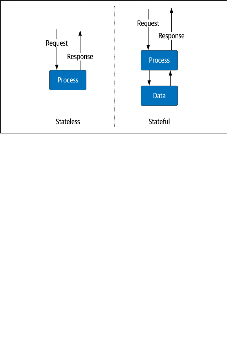
Figure 1-1. Stateless vs. Stateful Services
Stateless services
These are services that maintain information only for the immediate life cycle of
the active request—for example, a service for sending formatted shopping cart
information to a mobile client. A typical example is an application server that
performs the business logic for the shopping cart. However, the information
about the shopping cart contents resides external to these services. They only
need to be online for a short duration from request to response. The infrastruc‐
ture used to provide the service can easily grow and shrink with little impact on
the overall application. Scaling compute and network resources on-demand
when needed. Since we are not storing critical data in the individual service, they
can be created and destroyed quickly with little coordination. Stateless services
are a crucial architecture element in distributed systems.
Stateful services
These services need to maintain information from one request to the next. Disks
and memory store data for use across multiple requests. An example is a database
or file system. Scaling stateful services is much more complex since the informa‐
tion typically requires replication for high availability, which creates the need for
consistency and mechanisms to keep data in sync. These services usually have
different scaling methods, both vertical and horizontal. As a result, they require
different sets of operational tasks than stateless services.
Infrastructure Types | 9

In addition to how information is stored, we’ve also seen a shift towards developing
systems that embrace automated infrastructure deployment. These recent advances
include:
•
Physical servers gave way to virtual machines that could be deployed and main‐
tained easily.
•
Virtual machines eventually became greatly simplified and focused on specific
applications to what we now call containers.
• Containers have allowed infrastructure engineers to package an application’s
operating system requirements into a single executable.
The use of containers has undoubtedly increased the consistency of deployments,
which has made it easier to deploy and run infrastructure in bulk. Few systems
emerged to orchestrate the explosion of containers like Kubernetes which is evident
in the incredible growth. This speaks to how well it solves the problem. According to
the Kubernetes documentation:
Kubernetes is a portable, extensible, open-source platform for managing containerized
workloads and services that facilitates both declarative configuration and automation.
It has a large, rapidly growing ecosystem. Kubernetes services, support, and tools are
widely available.
Kubernetes was originally designed for stateless workloads, and that is what it has tra‐
ditionally done best. Kubernetes has developed a reputation as a “platform for build‐
ing platforms” in a cloud-native way. However, there’s a reasonable argument that a
complete cloud-native solution has to take data into account. That’s the goal of this
book: exploring how we make it possible to build cloud-native data solutions on
Kubernetes. But first, let’s unpack what that term means.
What is Cloud Native Data?
Let’s begin defining the aspects of cloud native data that can help us with a final defi‐
nition. First, let’s start with the definition of cloud native from the Cloud Native
Computing Foundation (CNCF):
Cloud native technologies empower organizations to build and run scalable applica‐
tions in modern, dynamic environments such as public, private, and hybrid clouds.
Containers, service meshes, microservices, immutable infrastructure, and declarative
APIs exemplify this approach.
These techniques enable loosely coupled systems that are resilient, manageable, and
observable. Combined with robust automation, they allow engineers to make high-
impact changes frequently and predictably with minimal toil.
Note that this definition describes a goal state, desirable characteristics, and examples
of technologies that embody both. Based on this formal definition, we can synthesize
10 | Chapter 1: Introduction to Cloud Native Data Infrastructure: Persistence, Streaming, and Batch Analytics

the qualities that make a cloud native application differentiated from other types of
deployments in terms of how it handles data. Let’s take a closer look at these qualities.
Scalability
If a service can produce a unit of work for a unit of resources, then adding more
resources should increase the amount of work a service can perform. Scalability
is how we describe the service’s ability to apply additional resources to produce
additional work. Ideally, services should scale infinitely given an infinite amount
of resources of compute, network and storage. For data this means scale without
the need for downtime. Legacy systems required a maintenance period while
adding new resources which all services had to be shutdown. With the needs of
cloud native applications, downtime is no longer acceptable.
Elasticity
Where scale is adding resources to meet demand, elastic infrastructure is the
ability to free those resources when no longer needed. The difference between
scalability and elasticity is highlighted in Figure 1-2. Elasticity can also be called
on-demand infrastructure. In a constrained environment such as a private data
center, this is critical for sharing limited resources. For cloud infrastructure that
charges for every resource used, this is a way to prevent paying for running serv‐
ices you don’t need. When it comes to managing data, this means that we need
capabilities to reclaim storage space and optimize our use, such as moving older
data to less expensive storage tiers.
Self-healing
Bad things happen and when they do, how will your infrastructure respond? Self-
healing infrastructure will re-route traffic, re-allocate resources, and maintain
service levels. With larger and more complex distributed applications being
deployed, this is an increasingly important attribute of a cloud-native application.
This is what keeps you from getting that 3 AM wake-up call. For data, this means
we need capabilities to detect issues with data such as missing data and data qual‐
ity.
Observability
If something fails and you aren’t monitoring it, did it happen? Unfortunately, the
answer is not only yes, but that can be an even worse scenario. Distributed appli‐
cations are highly dynamic and visibility into every service is critical for main‐
taining service levels. Interdependencies can create complex failure scenarios
which is why observability is a key part of building cloud native applications. In
data systems the volumes that are commonplace need efficient ways of monitor‐
ing the flow and state of infrastructure. In most cases, early warning for issues
can help operators avoid costly downtime.
What is Cloud Native Data? | 11
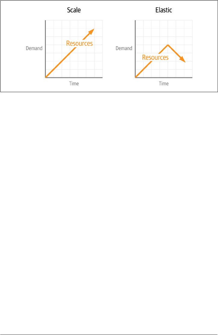
Figure 1-2. Comparing Scalability and Elasticity
With all of the previous definitions in place, let’s try a definition that expresses these
properties.
Cloud Native Data
Cloud Native Data approaches empower organizations that have adopted the
cloud native application methodology to incorporate data holistically rather than
employ the legacy of people, process, technology, so that data can scale up and
down elastically, and promote observability and self-healing.
This is exemplified by containerized data, declarative data, data APIs, data-
meshes, and cloud-native data infrastructure (that is, databases, streaming, and
analytics technologies that are themselves architected as cloud-native applica‐
tions).
In order for data infrastructure to keep parity with the rest of our application, we
need to incorporate each piece. This includes automation of scale, elasticity and self-
healing, APIs are needed to decouple services and increase developer velocity, and
also the ability to observe the entire stack of your application to make critical deci‐
sions. Taken as a whole, your application and data infrastructure should appear as
one unit.
More Infrastructure, More Problems
Whether your infrastructure is in a cloud, on-premises, or both (commonly referred
to as hybrid), you could spend a lot of time doing manual configuration. Typing
things into an editor and doing incredibly detailed configuration work requires deep
knowledge of each technology. Over the past twenty years, there have been significant
advances in the DevOps community to code and how we deploy our infrastructure.
This is a critical step in the evolution of modern infrastructure. DevOps has kept us
ahead of the scale required, but just barely. Arguably, the same amount of knowledge
12 | Chapter 1: Introduction to Cloud Native Data Infrastructure: Persistence, Streaming, and Batch Analytics
is needed to fully script a single database server deployment. It’s just that now we can
do it a million times over if needed with templates and scripts. What has been lacking
is a connectedness between the components and a holistic view of the entire applica‐
tion stack. Foreshadowing: this is a problem that needed to be solved.
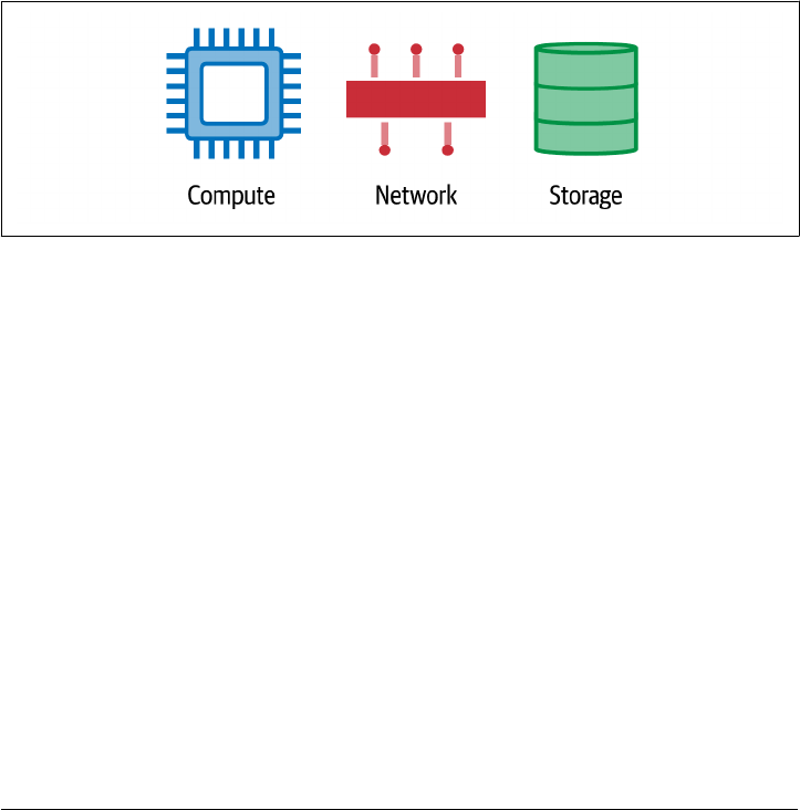
Like any good engineering problem, let’s break it down into manageable parts. The
first is resource management. Regardless of the many ways we have developed to
work at scale, fundamentally, we are trying to manage three things as efficiently as
possible: compute, network and storage, as shown in Figure 1-3. These are the critical
resources that every application needs and the fuel that’s burned during growth. Not
surprisingly, these are also the resources that carry the monetary component to a run‐
ning application. We get rewarded when we use the resources wisely and pay a literal
high price if we don’t. Anywhere you run your application, these are the most primi‐
tive units. When on-prem, everything is bought and owned. When using the cloud,
we’re renting.
Figure 1-3. Fundamental resources of cloud applications: compute, network, and storage
The second part of this problem is the issue of an entire stack acting as a single entity.
DevOps has already given us many tools to manage individual components, but the
connective tissue between them provides the potential for incredible efficiency. Simi‐
lar to how applications are packaged for the desktop but working at data center scales.
That potential has launched an entire community around cloud native applications.
These applications are very similar to what we have always deployed. The difference
is that modern cloud applications aren’t a single process with business logic. They are
a complex coordination of many containerized processes that need to communicate
securely and reliably. Storage has to match the current needs of the application but
remains aware of how it contributes to the stability of the application. When we think
of deploying stateless applications without data managed in the same control plane, it
sounds incomplete because it is. Breaking up your application components into dif‐
ferent control planes creates more complexity and is counter to the ideals of cloud
native.
More Infrastructure, More Problems | 13
Kubernetes Leading the Way
As mentioned before, DevOps automation has kept us on the leading edge of meeting
scale needs. Containers created the need for much better orchestration, and the
answer has been Kubernetes. For operators, describing a complete application stack
in a deployment file makes a reproducible and portable infrastructure. This is because
Kubernetes has gone far beyond simply the deployment management that has been
popular in the DevOps tool bag. The Kubernetes control plane applies the deploy‐
ment requirement across the underlying compute, network, and storage to manage
the entire application infrastructure lifecycle. The desired state of your application is
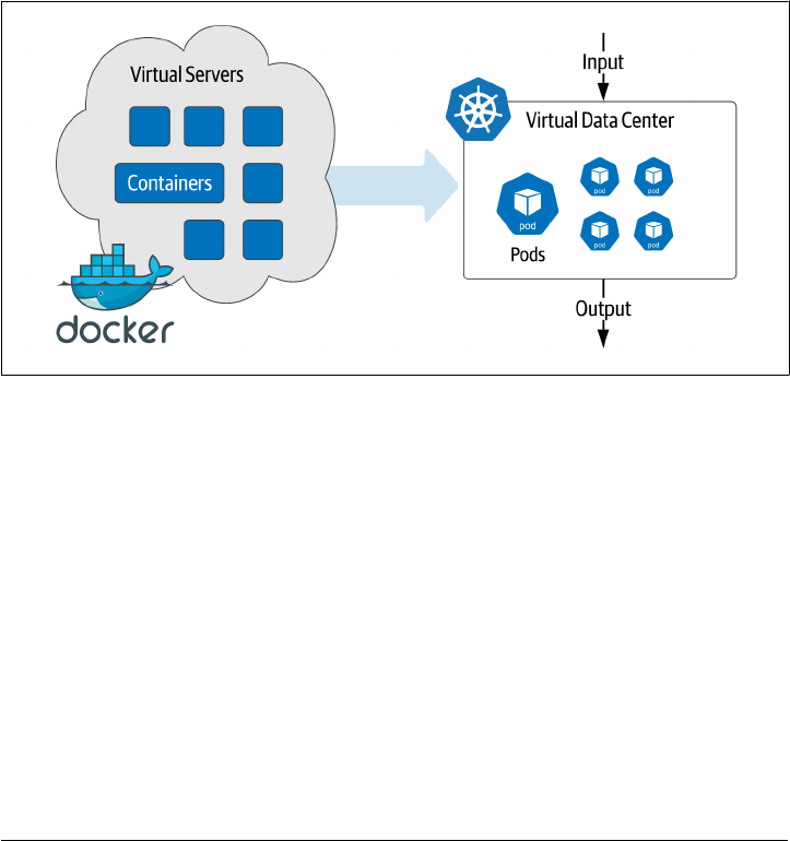
maintained even when the underlying hardware changes. Instead of deploying virtual
machines, we are now deploying virtual datacenters as a complete definition as
shown in Figure 1-4.
Figure 1-4. Moving from virtual servers to virtual data centers
The rise in popularity of Kubernetes has eclipsed all other container orchestration
tools used in DevOps. It has overtaken every other way we deploy infrastructure, and
it will be even more so in the future. There’s no sign of it slowing down. However, the
bulk of early adoption was primarily in stateless services.
Managing data infrastructure at a large scale was a problem well before the move to
containers and Kubernetes. Stateful services like databases took a different track par‐
allel to the Kubernetes adoption curve. Many recommended that Kubernetes was the
wrong way to run stateful services based on an architecture that favored ephemeral
workloads. That worked until it didn’t and is now driving the needed changes in
Kubernetes to converge the application stack.
So what are the challenges of stateful services? Why has it been hard to deploy data
infrastructure with Kubernetes? Let’s consider each component of our infrastructure.
14 | Chapter 1: Introduction to Cloud Native Data Infrastructure: Persistence, Streaming, and Batch Analytics

Managing Compute on Kubernetes
In data infrastructure, counting on Moore’s law has made upgrading a regular event.
If you aren’t familiar, Moore’s law predicted that computing capacity doubles every 18
months. If your requirements double every 18 months, you can keep up by replacing
hardware. Eventually, raw compute power started leveling out. Vendors started
adding more processors and cores to keep up with Moore’s law, leading to single
server resource sharing with virtual machines and containers. Enabling us to tap into
the vast pools of computing power left stranded in islands of physical servers. Kuber‐
netes expanded the scope of compute resource management by considering the total
datacenter as one large resource pool across multiple physical devices.
Sharing compute resources with other services has been somewhat taboo in the data
world. Data workloads are typically resource intensive, and the potential of one ser‐
vice impacting another (known as the noisy neighbor problem) has led to policies of
keeping them isolated from other workloads. This one-size fits all approach elimi‐
nates the possibility for more significant benefits. First is the assumption that all data
service resource requirements are the same. Apache Pulsar™ brokers can have far
fewer requirements than an Apache Spark™ worker, and neither are similar to a sizea‐
ble MySQL instance used for OLAP reporting. Second, the ability to decouple your
underlying hardware from running applications gives operators a lot of undervalued
flexibility. Cloud native applications that need scale, elasticity, and self-healing need
what Kubernetes can deliver. Data is no exception.
Managing Network on Kubernetes
Building a distributed application, by nature, requires a reliable and secure network.
Cloud native applications increase the complexity of adding and subtracting services
making dynamic network configuration a new requirement. Kubernetes manages all
of this inside of your virtual data center automatically. When new services come
online, it’s like a virtual network team springs to action. IP addresses are assigned,
routes are created, DNS entries are added, then the virtual security team ensures fire‐
wall rules are in place, and when asked, TLS certificates provide end-to-end encryp‐
tion.
Data infrastructure tends to be far less dynamic than something like microservices. A
fixed IP with a hostname has been the norm for databases. Analytic systems like
Apache Flink™ are dynamic in processing but have fixed hardware addressing assign‐
ments. Quality of service is typically at the top of the requirements list and, as a
result, the desire for dedicated hardware and dedicated networks has turned adminis‐
trators off of Kubernetes.
The advantage of data infrastructure running in Kubernetes is less about the past
requirements and more about what’s needed for the future. Scaling resources dynami‐
cally can create a waterfall of dependencies. Automation is the only way to maintain
Kubernetes Leading the Way | 15

clean and efficient networks, which are the lifeblood of distributed stateless systems.
The future of cloud native applications will only include more components and new
challenges such as where applications run. We can add regulatory compliance and
data sovereignty to previous concerns about latency and throughput. The declarative
nature of Kubernetes networks make it a perfect fit for data infrastructure.
Managing Storage on Kubernetes
Any service that provides persistence or analytics over large volumes of data will need
the right kind of storage device. Early versions of Kubernetes considered storage a
basic commodity part of the stack and assumed that most workloads were ephemeral.
For data, this was a huge mismatch. If your Postgres data files get deleted every time a
container is moved, that just doesn’t work. Additionally, implementing the underlying
block storage can be a broad spectrum. From high performance NVMe disks to old
5400 RPM spinning disks. You may not know what you’ll get. Thankfully this was an
essential focus of Kubernetes over the past few years and has been significantly
improved.
With the addition of features like Storage Classes, it is possible to address specific
requirements for performance or capacity or both. With automation, we can avoid
the point when you don’t have enough of either. Avoiding surprises is the domain of
capacity management—both initializing the needed capacity and growing when
required. When you run out of capacity in your storage, everything grinds to a halt.
Coupling the distributed nature of Kubernetes with data storage opens up more pos‐
sibilities for self healing. Automated backups and snapshots keep you ready for
potential data loss scenarios. Placing compute and storage together to minimize
hardware failure risks and automatic recovery to the desired state when the inevitable
failure occurs. All of which makes the data storage aspects of Kubernetes much more
attractive.
Cloud native data components
Now that we have defined the resources consumed in cloud native applications let’s
clarify the types of data infrastructure that powers them. Instead of a comprehensive
list of every possible product, we’ll break them down into larger buckets with similar
characteristics.
Persistence
This is probably assumed when we talk about data infrastructure. Systems that
store data and provide access by some method of a query. Relational databases
like MySQL and Postgres. NoSQL systems like Cassandra and MongoDB. In the
world of Kubernetes these have been the strongest, last holdouts due to the strict‐
est resource requirements. This has been for good reasons too. Databases are
16 | Chapter 1: Introduction to Cloud Native Data Infrastructure: Persistence, Streaming, and Batch Analytics

usually critical to a running application and central to every other part of the sys‐
tem.
Streaming
The most basic function of streaming is facilitating the high-speed movement of
data from one point to another. Streaming systems provide a variety of delivery
semantics based on a use case. In some cases, data can be delivered to many cli‐
ents or when strict controls are needed, delivered only once. A further enhance‐
ment of streaming is the addition of processing. Altering or enhancing data while
in mid-transport. The need for faster insights into data has propelled streaming
analytics into mission critical status catching up with persistence systems for
importance. Examples of steaming systems that move data are Apache Flink™ and
Apache Kafka™, where processing system examples are Apache Flink™ and
Apache Storm™.
Batch Analytics
One of the first big data problems. Analyzing large sets of data to gain insights or
re-purpose into new data. Apache Hadoop™ was the first large scale system for
batch analytics that set the expectations around using large volumes of compute
and storage, coordinated in a way to produce a final result. Typically, these are
issued as jobs distributed throughout the cluster which is something that is found
in Apache Spark™. The concern with costs can be much more prevalent in these
systems due to the sheer volume of resources needed. Orchestration systems help
mitigate the costs by intelligent allocation.
Looking forward
There is a very compelling future with cloud native data, both with what we have
available today and what we can have in the future. The path we take between those
two points is up to us: the community of people responsible for data infrastructure.
Just as we have always done, we see a new challenge and take it on. There is plenty for
everyone to do here, but the result could be pretty amazing and raise the bar, yet
again.
A call for databases to modernize on Kubernetes
With Rick Vasquez, Senior Director, Strategic Initiatives, Western Digital
Kubernetes is the catalyst for this current macro trend of change. Data infrastructure
has to run the same as the rest of the application infrastructure. In a conference talk,
Rick Vasquez, a leader in data infrastructure for years, wrote an open letter to the
database community on the need for change. Here is a summary of that talk:
Looking forward | 17

This is something for anyone working with databases in the 2020s. Kubernetes is
leading the charge in building cloud native and distributed systems. Data systems
aren’t leveraging the full capacity and feature set possible if they were better integrated
with Kubernetes. I’m a convert from the “you should never run a database in a con‐
tainer” way of thinking. Now I think we should be pushing everybody to have the
main deployment in Kubernetes. My background has always been on scale enterprise
use cases. I don’t see this as a passing fad, I’m looking at the applicability to global
scale for some of the largest companies in the world.
One line of thinking we need to overcome is treating Kubernetes like an operating
system that enables other applications to run on it. That’s the wrong way to look at
running data workloads. If your system runs in a container, then of course it will
work on Kubernetes, right? No! It will react to how the control plane deploys and
runs your application, and it may or may not be what you want. What if data systems
were more tightly integrated with Kubernetes and could offload functions to be han‐
dled by the Kubernetes control plane? Service discovery, load balancing, storage
orchestration, automated rollouts, and rollbacks, automated bin packing, self-healing,
secret and config management are all powerful things that allow for you to have a
consistent developer and SRE experience. The name of the game with Kubernetes is
driving consistency. You can use Kubernetes to become globally consistent across all
your deployments and do them the same way over and over. But that needs to include
database systems. Imagine if you have Postgres, MongoDB, MySQL, or Cassandra and
it was built natively on Kubernetes. What would you do?
Having the access to use different storage tiers, either local or remote disk. All of it
declarative in some configuration objects. I want to configure that in and with the
database. If I’m using MySQL, I want logs to be on the local disk, because I don’t want
any bottlenecks. I want certain tables to be on a slower disk that may be over the net‐
work. And, I want the last seven days of data to be in hot, local NVMe disk. Using
every single bit of capacity that you have with replicas actually doing things like off‐
loading reads or multiple write nodes, and one big aggregate for analytics. All of those
things should be possible with a Kubernetes based deployment with a cloud native
database.
Databases don’t reason about or have an opinion about how big they are. If you make
it bigger, it just needs more resources. You can set up auto-scaling to get you bigger or
horizontal scaling. What happens whenever you want to use the true elasticity that’s
given to you by Kubernetes? It’s not just the scale up and out. It’s the scale back and
down! Why don’t databases just do that? That is so important to maximize the value
that you’re getting out of a Kubernetes based deployment or more broadly, a cloud
native based deployment. We have a lot of work to do but the future is worth it.
This talk was specifically about databases, but we can extrapolate his call to action for
our data infrastructure running on Kubernetes. Unlike deploying a data application
18 | Chapter 1: Introduction to Cloud Native Data Infrastructure: Persistence, Streaming, and Batch Analytics

on physical servers, introducing the Kubernetes control plane requires a conversation
with the services it runs.
Getting ready for the revolution
As engineers that create and run data infrastructure, we have to be ready for the
changes coming. Both in how we operate and the mindset we have about the role of
data infrastructure. The following sections are meant to describe what you can do to
be ready for the future of cloud native data running in Kubernetes.
Adopt an SRE mindset
The role of Site Reliability Engineer (SRE) has grown with the adoption of cloud
native methodologies. If we intend our infrastructure to converge, we as data infra‐
structure engineers must learn new skills and adopt new practices.
Site reliability engineering is a set of principles and practices that incorporates aspects
of software engineering and applies them to infrastructure and operations problems.
The main goals are to create scalable and highly reliable software systems. Site relia‐
bility engineering is closely related to DevOps, a set of practices that combine soft‐
ware development and IT operations, and SRE has also been described as a specific
implementation of DevOps.
Deploying data infrastructure has been primarily concerned with the specific compo‐
nents deployed - the “what.” For example, you may find yourself focused on deploy‐
ing MySQL at scale or using Apache Spark to analyze large volumes of data. Adopting
an SRE mindset means going beyond what you are deploying and putting a greater
focus on the how. How will all of the pieces work together to meet the goals of the
application? A holistic view of a deployment considers how each piece will interact,
the required access including security, and the observability of every aspect to ensure
meeting service levels.
If your current primary or secondary role is Database Administrator, there is no bet‐
ter time to make the transition. The trend on LinkedIn shows a year-over-year
decrease in the DBA role and a massive increase for SREs. Engineers that have
learned the skills required to run critical database infrastructure have an essential
baseline that translates into what’s needed to manage cloud native data. These
include:
• Availability
• Latency
• Change Management
•
Emergency response
Getting ready for the revolution | 19

• Capacity Management
New skills need to be added to this list to become better adapted to the more signifi‐
cant responsibility of the entire application. These are skills you may already have,
but they include:
CI/CD pipelines
Embrace the big picture of taking code from repository to production. There’s
nothing that accelerates application development more in an organization. Con‐
tinuous Integration (CI) builds new code into the application stack and auto‐
mates all testing to ensure quality. Continuous Deployment (CD) takes the fully
tested and certified builds and automatically deploys them into production. Used
in combination (Pipeline), organizations can drastically increase developer veloc‐
ity and productivity.
Observability
Monitoring is something anyone with experience in infrastructure is familiar
with. In the “what” part of DevOps you know services are healthy and have the
information needed to diagnose problems. Observability expands monitoring
into the “how” of your application by considering everything as a whole. For
example, tracing the source of latency in a highly distributed application by giv‐
ing insight into every hop data takes.
Knowing the code
When things go bad in a large distributed application it’s not always a process
failure. In many cases, it could be a bug in the code or subtle implementation
detail. Being responsible for the entire health of the application, you will need to
understand the code that is executing in the provided environment. Properly
implemented observability will help you find problems and that includes the
software instrumentation. SREs and development teams need to have clear and
regular communication and code is common ground.
Embrace Distributed Computing
Deploying your applications in Kubernetes means embracing all of what distributed
computing offers. When you are accustomed to single system thinking, it can be a
hard transition. Mainly in the shift in thinking around expectations and understand‐
ing where problems crop up. For example, with every process contained in a single
system, latency will be close to zero. It’s not what you have to manage. CPU and
memory resources are the primary concern there. In the 1990s, Sun Microsystems
was leading in the growing field of distributed computing and published this list of
common fallacies:
1.
The network is reliable
20 | Chapter 1: Introduction to Cloud Native Data Infrastructure: Persistence, Streaming, and Batch Analytics

2. Latency is zero
3. Bandwidth is infinite
4. The network is secure
5.
Topology doesn’t change
6. There is one administrator
7.
Transport cost is zero
8. The network is homogeneous
These items most likely have an interesting story behind them where somebody
assumed one of these fallacies and found themselves very disappointed. The result
wasn’t what they expected and endless hours were lost trying to figure out the wrong
problem.
Embracing distributed methodologies is worth the effort in the long run. It is how we
build large scale applications and will be for a very long time. The challenge is worth
the reward, and for those of us who do this daily, it can be a lot of fun too! Kubernetes
applications will test each of these fallacies given its default distributed nature. When
you plan your deployment, considering things such as the cost of transport from one
place to another or latency implications. They will save you a lot of wasted time and
re-design.
Principles of Cloud Native Data Infrastructure
As engineering professionals, we seek standards and best-practices to build upon. To
make data the most “cloud native” it can be, we need to embrace everything Kuber‐
netes offers. A truly cloud native approach means adopting key elements of the
Kubernetes design paradigm and building from there. An entire cloud native applica‐
tion that includes data must be one that can run effectively on Kubernetes. Let’s
explore a few Kubernetes design principles that point the way.
Principle 1: Leverage compute, network, and storage as commodity APIs
One of the keys to the success of cloud computing is the commoditization of compu‐
tation, networking, and storage as resources we can provision via simple APIs. Con‐
sider this sampling of AWS services.
Compute
We allocate virtual machines through EC2 and Autoscaling Groups (ASGs).
Network
We manage traffic using Elastic Load Balancers (ELB), Route 53, and VPC peer‐
ing.
Getting ready for the revolution | 21

Storage
We persist data using options such as the Simple Storage Service (S3) for long-
term object storage, or Elastic Block Storage (EBS) volumes for our compute
instances.
Kubernetes offers its own APIs to provide similar services for a world of container‐
ized applications:
Compute
Pods, Deployments, and ReplicaSets manage the scheduling and life cycle of con‐
tainers on computing hardware.
Network
Services and Ingress expose a container’s networked interfaces.
Storage:
PersistentVolumes and Statefulets enable flexible association of containers to
storage.
Kubernetes resources promote the portability of applications across Kubernetes dis‐
tributions and service providers. What does this mean for databases? They are simply
applications that leverage computation, networking, and storage resources to provide
the services of data persistence and retrieval:
Compute
A database needs sufficient processing power to process incoming data and quer‐
ies. Each database node is deployed as a pod and grouped in StatefulSets, ena‐
bling Kubernetes to manage scaling out and scaling in.
Network
A database needs to expose interfaces for data and control. We can use Kuber‐
netes Services and Ingress Controllers to expose these interfaces.
Storage
A database uses persistent volumes of a specified storage class to store and
retrieve data.
Thinking of databases in terms of their compute, network, and storage needs removes
much of the complexity involved in deployment on Kubernetes.
Principle 2: Separate the control and data planes
Kubernetes promotes the separation of control and data planes. The Kubernetes API
server is the key data plane interface used to request computing resources, while the
control plane manages the details of mapping those requests onto an underlying IaaS
platform.
22 | Chapter 1: Introduction to Cloud Native Data Infrastructure: Persistence, Streaming, and Batch Analytics

We can apply this same pattern to databases. For example, a database data plane con‐
sists of ports exposed for clients, and for distributed databases, ports used for com‐
munication between database nodes. The control plane includes interfaces provided
by the database for administration and metrics collection and tooling that performs
operational maintenance tasks. Much of this capability can and should be imple‐
mented via the Kubernetes operator pattern. Operators define custom resources
(CRDs) and provide control loops that observe the state of those resources and take
actions to move them toward the desired state, helping extend Kubernetes with
domain-specific logic.
Principle 3: Make observability easy
The three pillars of observable systems are logging, metrics, and tracing. Kubernetes
provides a great starting point by exposing the logs of each container to third-party
log aggregation solutions. There are multiple solutions available for metrics, tracing,
and visualization, and we’ll explore several of them in this book.
Principle 4: Make the default
conguration secure
Kubernetes networking is secure by default: ports must be explicitly exposed in order
to be accessed externally to a pod. This sets a valuable precedent for database deploy‐
ment, forcing us to think carefully about how each control plane and data plane inter‐
face will be exposed and which interfaces should be exposed via a Kubernetes Service.
Kubernetes also provides facilities for secret management which can be used for shar‐
ing encryption keys and configuring administrative accounts.
Principle 5: Prefer declarative
conguration
In the Kubernetes declarative approach, you specify the desired state of resources,
and controllers manipulate the underlying infrastructure in order to achieve that
state. Operators for data infrastructure can manage the details of how to scale up
intelligently, for example, deciding how to reallocate shards or partitions when scal‐
ing out additional nodes or selecting which nodes to remove to scale down elastically.
The next generation of operators should enable us to specify rules for stored data size,
number of transactions per second, or both. Perhaps we’ll be able to specify maxi‐
mum and minimum cluster sizes, and when to move less frequently used data to
object storage. This will allow for more automation and efficiency in our data infra‐
structure.
Summary
At this point, we hope you are ready for the exciting journey in the pages ahead. The
move to cloud native applications must include data, and to do this, we will leverage
Kubernetes to include stateless and stateful services. This chapter covered cloud
Summary | 23

native data infrastructure that can scale elastically and resist any downtime due to
system failures and how to build these systems. We as engineers must embrace the
principles of cloud native infrastructure and in some cases, learn new skills. Congrat‐
ulations, you have begun a fantastic journey into the future of building cloud native
applications. Turn the page, and let’s go!
24 | Chapter 1: Introduction to Cloud Native Data Infrastructure: Persistence, Streaming, and Batch Analytics

CHAPTER 2
Managing Data Storage on Kubernetes
A Note for Early Release Readers
With Early Release ebooks, you get books in their earliest form—the author’s raw and
unedited content as they write—so you can take advantage of these technologies long
before the official release of these titles.
This will be the 2nd chapter of the final book. Please note that the GitHub repo will be
made active later on.
If you have comments about how we might improve the content and/or examples in
this book, or if you notice missing material within this chapter, please reach out to the
authors at [email protected] (Jeff Carpenter) and [email protected] (Pat‐
rick McFadin).
“There is no such thing as a stateless architecture. All applications store state some‐
where” - Alex Chircop, CEO, StorageOS
In the previous chapter, we painted a picture of a possible near future with powerful,
stateful, data-intensive applications running on Kubernetes. To get there, we’re going
to need data infrastructure for persistence, streaming, and analytics, and to build out
this infrastructure, we’ll need to leverage the primitives that Kubernetes provides to
help manage the three commodities of cloud computing: compute, network, and
storage. In the next several chapters we begin to look at these primitives, starting with
storage, in order to see how they can be combined to create the data infrastructure we
need.
To echo the point raised by Alex Chircop in the quote above, all applications must
store their state somewhere, which is why we’ll focus in this chapter on the basic
abstractions Kubernetes provides for interacting with storage. We’ll also look at the
25

emerging innovations being offered by storage vendors and open source projects that
are creating storage infrastructure for Kubernetes that itself embodies cloud-native
principles.
Let’s start our exploration with a look at managing persistence in containerized appli‐
cations in general and use that as a jumping off point for our investigation into data
storage on Kubernetes.
Docker, Containers, and State
The problem of managing state in distributed, cloud-native applications is not unique
to Kubernetes. A quick search will show that stateful workloads have been an area of
concern on other container orchestration platforms such as Mesos and Docker
Swarm. Part of this has to do with the nature of container orchestration, and part is
driven by the nature of containers themselves.
First, let’s consider containers. One of the key value propositions of containers is their
ephemeral nature. Containers are designed to be disposable and replaceable, so they
need to start quickly and use as few resources for overhead processing as possible. For
this reason, most container images are built from base images containing stream‐
lined, Linux-based, open-source operating systems such as Ubuntu, that boot quickly
and incorporate only essential libraries for the contained application or microservice.
As the name implies, containers are designed to be self-contained, incorporating all
their dependencies in immutable images, while their configuration and data is exter‐
nalized. These properties make containers portable so that we can run them any‐
where a compatible container runtime is available.
As shown in Figure 2-1, containers require less overhead than traditional virtual
machines, which run a guest operating system per virtual machine, with a hypervisor
layer to implement system calls onto the underlying host operating system.
26 | Chapter 2: Managing Data Storage on Kubernetes
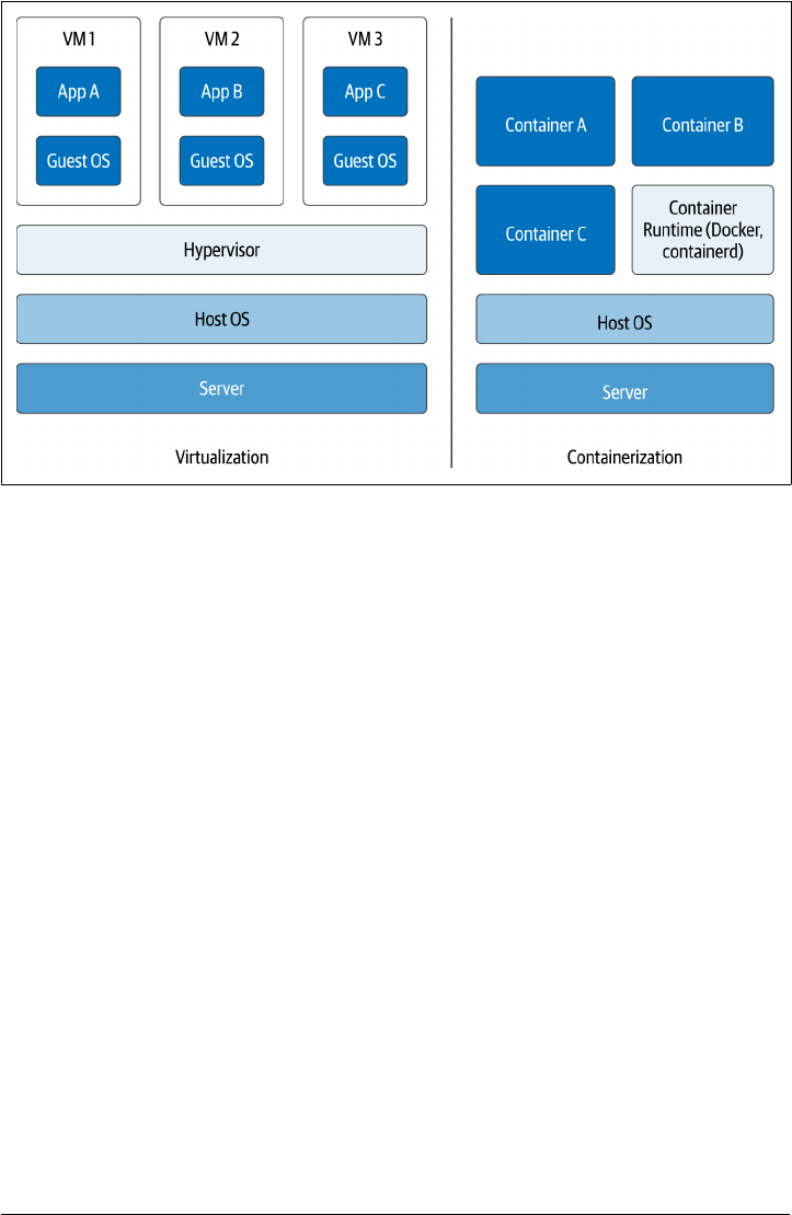
Figure 2-1. Comparing containerization to virtualization
Although containers have made applications more portable, it’s proven a bigger chal‐
lenge to make their data portable. We’ll examine the idea of portable data sets in
Chapter 12. Since a container itself is ephemeral, any data that is to survive beyond
the life of the container must by definition reside externally. The key feature for a
container technology is to provide mechanisms to link to persistent storage, and the
key feature for a container orchestration technology is the ability to schedule contain‐
ers in such a way that they can access persistent storage efficiently.
Managing State in Docker
Let’s take a look at the most popular container technology, Docker, to see how con‐
tainers can store data. The key storage concept in Docker is the volume. From the
perspective of a Docker container, a volume is a directory that can support read-only
or read-write access. Docker supports the mounting of multiple different data stores
as volumes. We’ll introduce several options so we can later note their equivalents in
Kubernetes.
Bind mounts
The simplest approach for creating a volume is to bind a directory in the container to
a directory on the host system. This is called a bind mount, as shown in Figure 2-2.
Docker, Containers, and State | 27
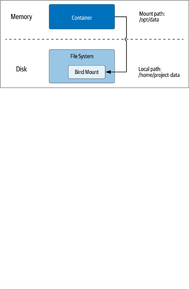
Figure 2-2. Using Docker Bind Mounts to access the host lesystem
When starting a container within Docker, you specify a bind mount with the --
volume or -v option and the local filesystem path and container path to use. For
example, you could start an instance of the Nginx web server, and map a local project
folder from your development machine into the container. This is a command you
can test out in your own environment if you have Docker installed:
docker run -it --rm -d --name web -v ~/site-content:/usr/share/nginx/html nginx
If the local path directory does not already exist, the Docker runtime will create it.
Docker allows you to create bind mounts with read-only or read-write permissions.
Because the volume is represented as a directory, the application running in the con‐
tainer can put anything that can be represented as a file into the volume - even a data‐
base.
Bind mounts are quite useful for development work. However, using bind mounts is
not suitable for a production environment since this leads to a container being
dependent on a file being present in a specific host. This might be fine for a single
machine deployment, but production deployments tend to be spread across multiple
hosts. Another concern is the potential security hole that is presented by opening up
access from the container to the host filesystem. For these reasons, we need another
approach for production deployments.
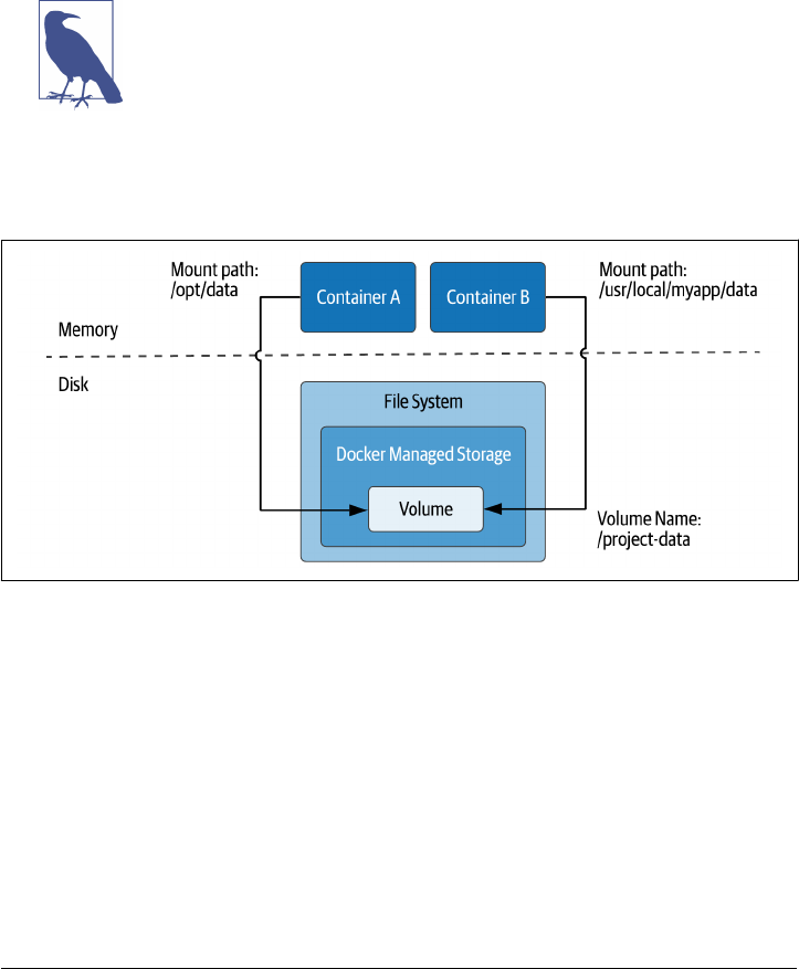
Volumes
The preferred option within Docker is to use volumes. Docker volumes are created
and managed by Docker under a specific directory on the host filesystem. The
Docker volume create command is used to create a volume. For example, you might
create a volume called site-content to store files for a website:
28 | Chapter 2: Managing Data Storage on Kubernetes
docker volume create site-content
If no name is specified, Docker assigns a random name. After creation, the resulting
volume is available to mount in a container using the form -v VOLUME-
NAME:CONTAINER-PATH. For example, you might use a volume like the one just created
to allow an Nginx container to read the content, while allowing another container to
edit the content, using the to option:
docker run -it --rm -d --name web -v site-content:/usr/share/nginx/html:ro nginx
Note: Docker Volume mount syntax
Docker also supports a --mount syntax which allows you to specify
the source and target folders more explicitly. This notation is con‐
sidered more modern, but it is also more verbose. The syntax
shown above is still valid and is the more commonly used syntax.
As implied above, a Docker volume can be mounted in more than one container at
once, as shown in Figure 2-3.
Figure 2-3. Creating Docker Volumes to share data between containers on the host
The advantage of using Docker volumes is that Docker manages the filesystem access
for containers, which makes it much simpler to enforce capacity and security restric‐
tions on containers.
Tmpfs Mounts
Docker supports two types of mounts that are specific to the operating system used
by the host system: tmpfs (or “temporary filesystem”) and named pipes. Named pipes
are available on Docker for Windows, but since they are typically not used in K8s, we
won’t give much consideration to them here.
Docker, Containers, and State | 29
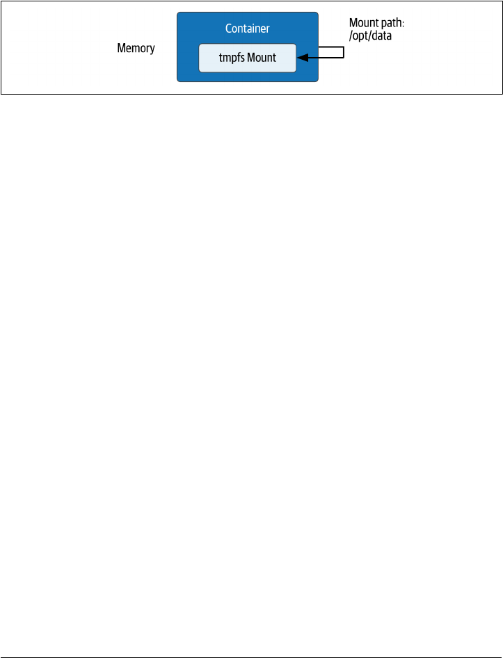
Tmpfs mounts are available when running Docker on Linux. A tmpfs mount exists
only in memory for the lifespan of the container, so the contents are never present on
disk, as shown in Figure 2-4. Tmpfs mounts are useful for applications that are writ‐
ten to persist a relatively small amount of data, especially sensitive data that you don’t
want written to the host filesystem. Because the data is stored in memory, there is a
side benefit of faster access.
Figure 2-4. Creating a temporary volume using Docker tmpfs
To create a tmpfs mount, you use the docker run --tmpfs option. For example, you
could use a command like this to specify a tmpfs volume to store Nginx logs for a
webserver processing sensitive data:
docker run -it --rm -d --name web -tmpfs /var/log/nginx nginx
The --mount option may also be used for more control over configurable options.
Volume Drivers
The Docker Engine has an extensible architecture which allows you to add custom‐
ized behavior via plugins for capabilities including networking, storage, and authori‐
zation. Third-party storage plugins are available for multiple open-source and
commercial providers, including the public clouds and various networked file sys‐
tems. Taking advantage of these involves installing the plugin with Docker engine
and then specifying the associated volume driver when starting Docker containers
using that storage, as shown in Figure 2-5.
30 | Chapter 2: Managing Data Storage on Kubernetes
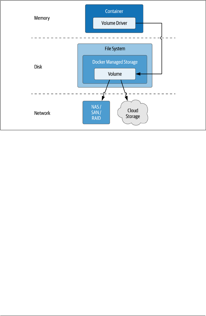
Figure 2-5. Using Docker Volume Drivers to access networked storage
For more information on working with the various types of volumes supported in
Docker, see the Docker Storage documentation, as well as the documentation for the
docker run command.
Sidebar: File, Block, and Object Storage
In our modern era of cloud architectures, the three main formats in which storage is
traditionally provided to applications are files, blocks, and objects. Each of these store
and provide access to data in different ways.
• File storage represents data as a hierarchy of folders, each of which can contain
files. The file is the basic unit of access for both storage and retrieval. The root
directory that is to be accessed by a container is mounted into the container file‐
system such that it looks like any other directory. Each of the public clouds pro‐
vides their own file storage, for example Google Cloud Filestore, or Amazon
Elastic Filestore. Gluster is an open-source distributed file system. Many of these
systems are compatible with the Network File System (NFS), a distributed file
system protocol invented at Sun Microsystems dating back to 1984 that is still in
common use.
• Block storage organizes data in chunks and allocates those chunks across a set of
managed volumes. When you provide data to a block storage system, it divides it
up into chunks of varying sizes and distributes those chunks in order to use the
Docker, Containers, and State | 31

underlying volumes the most efficiently. When you query a block storage system,
it retrieves the chunks from their various locations and provides the data back to
you. This flexibility makes block storage a great solution when you have a hetero‐
geneous set of storage devices available. Block storage doesn’t provide a lot of
metadata handling, which can place more burden on the application.
•
Object storage organizes data in units known as objects. Each object is referenced
by a unique identifier or “key”, and can support rich metadata tagging that ena‐
bles searching. Objects are organized in buckets. This flat, non-hierarchical orga‐
nization makes object storage easy to scale. Amazon’s Simple Storage Service (S3)
is the canonical example of object storage and most object storage products will
claim compatibility with the S3 API.
If you’re tasked with building or selecting data infrastructure, you’ll want to under‐
stand the strengths and weaknesses of each of these patterns.
Kubernetes Resources for Data Storage
Now that you understand basic concepts of container and cloud storage, let’s see what
Kubernetes brings to the table. In this section, we’ll introduce some of the key Kuber‐
netes concepts or “resources” in the API for attaching storage to containerized appli‐
cations. Even if you are already somewhat familiar with these resources, you’ll want
to stay tuned, as we’ll take a special focus on how each one relates to stateful data.
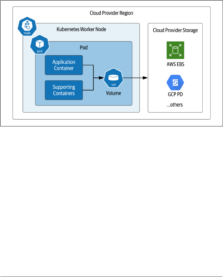
Pods and Volumes
One of the first Kubernetes resources new users encounter is the pod. The pod is the
basic unit of deployment of a Kubernetes workload. A pod provides an environment
for running containers, and the Kubernetes control plane is responsible for deploying
pods to Kubernetes worker nodes. The Kubelet is a component of the Kubernetes
control plane that runs on each worker node. It is responsible for running pods on a
node, as well as monitoring the health of these pods and the containers inside them.
These elements are summarized in Figure 2-6.
While a pod can contain multiple containers, the best practice is for a pod to contain
a single application container, along with optional additional helper containers, as
shown in the figure. These helper containers might include init containers that run
prior to the main application container in order to perform configuration tasks, or
sidecar containers that run alongside the main application container to provide
helper services such as observability or management. In future chapters we’ll demon‐
strate how data infrastructure deployments can take advantage of these architectural
patterns.
32 | Chapter 2: Managing Data Storage on Kubernetes
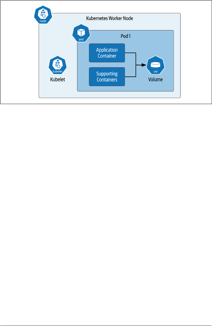
Figure 2-6. Using Volumes in Kubernetes Pods
Now let’s consider how persistence is supported within this pod architecture. As with
Docker, the “on disk” data in a container is lost when a container crashes. The kubelet
is responsible for restarting the container, but this new container is really a replace‐
ment for the original container - it will have a distinct identity, and start with a com‐
pletely new state.
In Kubernetes, the term volume is used to represent access to storage within a pod. By
using a volume, the container has the ability to persist data that will outlive the con‐
tainer (and potentially the pod as well, as we’ll see shortly). A volume may be accessed
by multiple containers in a pod. Each container has its own volumeMount within the
pod that specifies the directory to which it should be mounted, allowing the mount
point to differ between containers.
There are multiple cases where you might want to share data between multiple con‐
tainers in a pod:
• An init container creates a custom configuration file for the particular environ‐
ment that the application container mounts in order to obtain configuration val‐
ues.
• The application pod writes logs, and a sidecar pod reads those logs to identify
alert conditions that are reported to an external monitoring tool.
However, you’ll likely want to avoid situations in which multiple containers are writ‐
ing to the same volume, because you’ll have to ensure the multiple writers don’t con‐
flict - Kubernetes does not do that for you.
Kubernetes Resources for Data Storage | 33

Note: Preparing to run sample code
The examples in this chapter (and the rest of the book) assume you
have access to a running Kubernetes cluster. For the examples in
this chapter, a development cluster on your local machine such as
Kind, K3s, or Docker Desktop should be sufficient. The source
code used in this section is located at Kubernetes Storage Examples.
apiVersion: v1
kind: Pod
metadata:
name: my-pod
spec:
containers:
- name: my-app
image: nginx
volumeMounts:
- name: web-data
mountPath: /app/config
volumes:
- name: web-data
Notice the two parts of the configuration: the volume is defined under spec.volumes,
and the usage of the volumes is defined under spec.containers.volumeMounts. First,
the name of the volume is referenced under the volumeMounts, and the directory
where it is to be mounted is specified by the mountPath. When declaring a pod speci‐
fication, volumes and volume mounts go together. For your configuration to be valid,
a volume must be declared before being referenced, and a volume must be used by at
least one container in the pod.
You may have also noticed that the volume only has a name. You haven’t specified any
additional information. What do you think this will do? You could try this out for
yourself by using the example source code file nginx-pod.yaml or cutting and pasting
the configuration above to a file with that name, and executing the kubectl command
against a configured Kubernetes cluster:
kubectl apply -f nginx-pod.yaml
You can get more information about the pod that was created using the kubectl get
pod command, for example:
kubectl get pod my-pod -o yaml | grep -A 5 " volumes:”
And the results might look something like this:
volumes:
- emptyDir: {}
name: web-data
- name: default-token-2fp89
34 | Chapter 2: Managing Data Storage on Kubernetes

secret:
defaultMode: 420
As you can see, Kubernetes supplied some additional information when creating the
requested volume, defaulting it to a type of emptyDir. Other default attributes may
differ depending on what Kubernetes engine you are using and we won’t discuss them
further here.
There are several different types of volumes that can be mounted in a container, let’s
have a look.
Ephemeral volumes
You’ll remember tmpfs volumes from our discussion of Docker volumes above,
which provide temporary storage for the lifespan of a single container. Kubernetes
provides the concept of an ephemeral volumes, which is similar, but at the scope of a
pod. The emptyDir introduced in the example above is a type of ephemeral volume.
Ephemeral volumes can be useful for data infrastructure or other applications that
want to create a cache for fast access. Although they do not persist beyond the life‐
span of a pod, they can still exhibit some of the typical properties of other volumes
for longer-term persistence, such as the ability to snapshot. Ephemeral volumes are
slightly easier to set up than PersistentVolumes because they are declared entirely
inline in the pod definition without reference to other Kubernetes resources. As you
will see below, creating and using PersistentVolumes is a bit more involved.
Note: Other ephemeral storage providers
Some of the in-tree and CSI storage drivers we’ll discuss below that
provide PersistentVolumes also provide an ephemeral volume
option. You’ll want to check the documentation of the specific pro‐
vider in order to see what options are available.
Conguration volumes
Kubernetes provides several constructs for injecting configuration data into a pod as a
volume. These volume types are also considered ephemeral in the sense that they do
not provide a mechanism for allowing applications to persist their own data.
These volume types are relevant to our exploration in this book since they provide a
useful means of configuring applications and data infrastructure running on Kuber‐
netes. We’ll describe each of them briefly:
CongMap Volumes
A ConfigMap is a Kubernetes resource that is used to store configuration values
external to an application as a set of name-value pairs. For example, an applica‐
tion might require connection details for an underlying database such as an IP
Kubernetes Resources for Data Storage | 35

address and port number. Defining these in a ConfigMap is a good way to exter‐
nalize this information from the application. The resulting configuration data
can be mounted into the application as a volume, where it will appear as a direc‐
tory. Each configuration value is represented as a file, where the filename is the
key, and the contents of the file contain the value. See the Kubernetes documen‐
tation for more information on mounting ConfigMaps as volumes.
Secret Volumes
A Secret is similar to a ConfigMap, only it is intended for securing access to sen‐
sitive data that requires protection. For example, you might want to create a
secret containing database access credentials such as a username and password.
Configuring and accessing Secrets is similar to using ConfigMap, with the addi‐
tional benefit that Kubernetes helps decrypt the secret upon access within the
pod. See the Kubernetes documentation for more information on mounting
Secrets as volumes.
Downward API Volumes
The Kubernetes Downward API exposes metadata about pods and containers,
either as environment variables or as volumes. This is the same metadata that is
used by kubectl and other clients.
The available pod metadata includes the pod’s name, ID, namespace, labels, and
annotations. The containerized application might wish to use the pod informa‐
tion for logging and metrics reporting, or to determine database or table names.
The available container metadata includes the requested and maximum amounts
of resources such as CPU, memory, and ephemeral storage. The containerized
application might wish to use this information in order to throttle its own
resource usage. See the Kubernetes documentation for an example of injecting
pod information as a volume.
Hostpath volumes
A hostPath volume mounts a file or directory into a pod from the Kubernetes worker
node where it is running. This is analogous to the bind mount concept in Docker dis‐
cussed above. Using a hostPath volume has one advantage over an emptyDir volume:
the data will survive the restart of a pod.
However, there are some disadvantages to using hostPath volumes. First, in order for
a replacement pod to access the data of the original pod, it will need to be restarted
on the same worker node. While Kubernetes does give you the ability to control
which node a pod is placed on using affinity, this tends to constrain the Kubernetes
scheduler from optimal placement of pods, and if the node goes down for some rea‐
son, the data in the hostPath volume is lost. Second, similar to Docker bind mounts,
there is a security concern with hostPath volumes in terms of allowing access to the
36 | Chapter 2: Managing Data Storage on Kubernetes
local filesystem. For these reasons, hostPath volumes are only recommended for
development deployments.
Cloud Volumes
It is possible to create Kubernetes volumes that reference storage locations beyond just the
worker node where a pod is running, as shown in Figure 2-7. These can be grouped into volume
types that are provided by named cloud providers, and those that attempt to provide a more
generic interface. .
Figure 2-7. Kubernetes pods directly mounting cloud provider storage
.
These include the following:
• The awsElasticBlockStore volume type is used to mount volumes on Amazon
Web Services (AWS) Elastic Block Store (EBS). Many databases use block storage
as their underlying storage layer.
• The gcePersistentDisk volume type is used to mount Google Compute Engine
(GCE) persistent disks (PD), another example of block storage.
• Two types of volumes are supported for Microsoft Azure: azureDisk for Azure
Disk Volumes, and azureFile for Azure File Volumes
• For OpenStack deployments, the cinder volume type can be used to access Open‐
Stack Cinder volumes
Usage of these types typically requires configuration on the cloud provider, and
access from Kubernetes clusters is typically confined to storage in the same cloud
Kubernetes Resources for Data Storage | 37

region and account. Check your cloud provider’s documentation for additional
details.
Additional Volume Providers
There are a number of additional volume providers that vary in the types of storage
provided. Here are a few examples:
• The fibreChannel volume type can be used for SAN solutions implementing the
FibreChannel protocol.
•
The gluster volume type is used to access file storage using the Gluster dis‐
tributed file system referenced above
• An iscsi volume mounts an existing iSCSI (SCSI over IP) volume into your Pod.
• An nfs volume allows an existing NFS (Network File System) share to be moun‐
ted into a Pod
We’ll examine more volume providers below that implement the Container Attached
Storage pattern.
Table 2-1 provides a comparison of Docker and Kubernetes storage concepts we’ve
covered so far.
Table 2-1. Table 2-1: Comparing Docker and Kubernetes storage options
Type of Storage Docker Kubernetes
Access to persistent storage from various providers Volume (accessed via
Volume drivers)
Volume (accessed via in-tree or CSI
drivers)
Access to host
lesystem (not recommended for
production)
Bind mount Hostpath volume
Temporary storage available while container (or pod) is
running
tmpfs emptyDir and other ephemeral
volumes
Conguration
and environment data (read-only)
(no direct equivalent) CongMap,
Secret, Downward API
Sidebar: How do you choose a Kubernetes storage solution?
Given the number of storage options available, it can certainly be an intimidating task
to try to determine what kind of storage you should use for your application. Along
with determining whether you need file, block, or object storage, you’ll want to con‐
sider your latency and throughput requirements, as well as your expected storage vol‐
ume. For example, If your read latency requirements are aggressive, you’ll most likely
need a storage solution that keeps data in the same data center where it is accessed.
Next, you’ll want to consider any existing commitments or resources you have. Per‐
haps your organization has a mandate or bias toward using services from a preferred
cloud provider. The cloud providers will frequently provide cost incentives for using
38 | Chapter 2: Managing Data Storage on Kubernetes

their services, but you’ll want to trade this against the risk of lock-in to a specific ser‐
vice. Alternatively, you might have an investment in a storage solution in an on-
premises data center that you need to leverage.
Overall, cost tends to be the overriding factor in choosing storage solutions, espe‐
cially over the long term. Make sure your modeling includes not only the cost of the
physical storage and any managed services, but also the operational cost involved in
managing your chosen solution.
In this section, we’ve discussed how to use volumes to provide storage that can be
shared by multiple containers within the same pod. While this is sufficient for some
use cases, there are some needs this doesn’t address. A volume does not provide the
ability to share storage resources between pods. The definition of a particular storage
location is tied to the definition of the pod. Managing storage for individual pods
doesn’t scale well as the number of pods deployed in your Kubernetes cluster increa‐
ses.
Thankfully, Kubernetes provides additional primitives that help simplify the process
of provisioning and mounting storage volumes for both individual pods and groups
of related pods. We’ll investigate these concepts in the next several sections.
PersistentVolumes
The key innovation the Kubernetes developers have introduced for managing storage
is the persistent volume subsystem. This subsystem consists of three additional
Kubernetes resources that work together: PersistentVolumes, PersistentVolume‐
Claims, and StorageClasses. This allows you to separate the definition and lifecycle of
storage from how it is used by pods, as shown in Figure 2-8:
•
Cluster administrators define PersistentVolumes, either explicitly or by creating a
StorageClass that can dynamically provision new PersistentVolumes.
• Application developers create PersistentVolumeClaims that describe the storage
resource needs of their applications, and these PersistentVolumeClaims can be
referenced as part of volume definitions in pods.
•
The Kubernetes control plane manages the binding of PersistentVolumeClaims
to PersistentVolumes.
Kubernetes Resources for Data Storage | 39
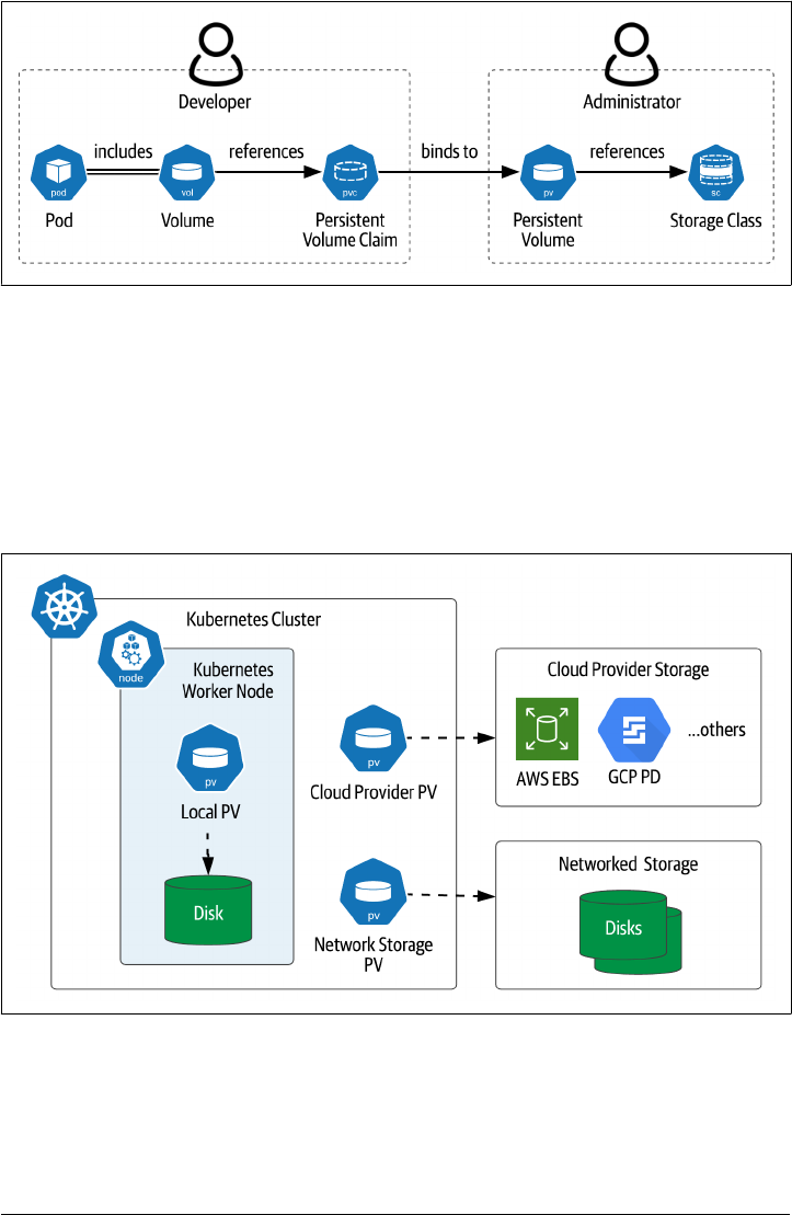
Figure 2-8. PersistentVolumes, PersistentVolumeClaims, and StorageClasses
Let’s look first at the PersistentVolume resource (often abbreviated PV), which
defines access to storage at a specific location. PersistentVolumes are typically defined
by cluster administrators for use by application developers. Each PV can represent
storage of the same types discussed in the previous section, such as storage offered by
cloud providers, networked storage, or storage directly on the worker node, as shown
in Figure 2-9. Since they are tied to specific storage locations, PersistentVolumes are
not portable between Kubernetes clusters.
Figure 2-9. Types of Kubernetes PersistentVolumes
Local PersistentVolumes
The figure also introduces a PersistentVolume type called local, which represents
storage mounted directly on a Kubernetes worker node such as a disk or partition.
40 | Chapter 2: Managing Data Storage on Kubernetes

Like hostPath volumes, a local volume may also represent a directory. A key differ‐
ence between local and hostPath volumes is that when a pod using a local volume is
restarted, the Kubernetes scheduler ensures the pod is rescheduled on the same node
so that it can be attached to the same persistent state. For this reason, local volumes
are frequently used as the backing store for data infrastructure that manages its own
replication, as we’ll see in Chapter 4.
The syntax for defining a PersistentVolume will look familiar, as it is similar to defin‐
ing a volume within a pod. For example, here is a YAML configuration file that
defines a local PersistentVolume (source code):
apiVersion: v1
kind: PersistentVolume
metadata:
name: my-volume
spec:
capacity:
storage: 3Gi
accessModes:
- ReadWriteOnce
local:
path: /app/data
nodeAffinity:
required:
nodeSelectorTerms:
- matchExpressions:
- key: kubernetes.io/hostname
operator: In
values:
- node1
As you can see, this code defines a local volume named my-volume on the worker
node node1, 3 GB in size, with an access mode of ReadWriteOnce. The following
access modes are supported for PersistentVolumes:
• ReadWriteOnce access allows the volume to be mounted for both reading and
writing by a single pod at a time, and may not be mounted by other pods
•
ReadOnlyMany access means the volume can be mounted by multiple pods simul‐
taneously for reading only
• ReadWriteMany access allows the volume to be mounted for both reading and
writing by many nodes at the same time
Kubernetes Resources for Data Storage | 41

Note: Choosing a volume access mode
The right access mode for a given volume will be driven by the type
of workload. For example, many distributed databases will be con‐
figured with dedicated storage per pod, making ReadWriteOnce a
good choice.
Besides capacity and access mode, other attributes for PersistentVolumes include:
• The volumeMode, which defaults to Filesystem but may be overridden to Block.
•
The reclaimPolicy defines what happens when a pod releases its claim on this
PersistentVolume. The legal values are Retain, Recycle, and Delete.
• A PersistentVolume can have a nodeAffinity which designates which worker
node or nodes can access this volume. This is optional for most types, but
required for the local volume type.
• The class attribute binds this PV to a particular StorageClass, which is a concept
we’ll introduce below.
•
Some PersistentVolume types expose mountOptions that are specific to that type.
Warning: Differences in volume options
Options differ between different volume types. For example, not
every access mode or reclaim policy is accessible for every Persis‐
tentVolume type, so consult the documentation on your chosen
type for more details.
You use the kubectl describe persistentvolume command (or kubectl describe pv
for short) to see the status of the PersistentVolume:
$ kubectl describe pv my-volume
Name: my-volume
Labels: <none>
Annotations: <none>
Finalizers: [kubernetes.io/pv-protection]
StorageClass:
Status: Available
Claim:
Reclaim Policy: Retain
Access Modes: RWO
VolumeMode: Filesystem
Capacity: 3Gi
Node Affinity:
Required Terms:
Term 0: kubernetes.io/hostname in [node1]
Message:
42 | Chapter 2: Managing Data Storage on Kubernetes

Source:
Type: LocalVolume (a persistent volume backed by local storage on a node)
Path: /app/data
Events: <none>
The PersistentVolume has a status of Available when first created. A PersistentVo‐
lume can have multiple different status values:
• Available means the PersistentVolume is free, and not yet bound to a claim.
•
Bound means the PersistentVolume is bound to a PersistentVolumeClaim, which
is listed elsewhere in the describe output
• Released means that an existing claim on the PersistentVolume has been deleted,
but the resource has not yet been reclaimed, so the resource is not yet Available
• Failed means the volume has failed its automatic reclamation
Now that you’ve learned how storage resources are defined in Kubernetes, the next
step is to learn how to use that storage in your applications.
PersistentVolumeClaims
As discussed above, Kubernetes separates the definition of storage from its usage.
Often these tasks are performed by different roles: cluster administrators define stor‐
age, while application developers use the storage. PersistentVolumes are typically
defined by the administrators and reference storage locations which are specific to
that cluster. Developers can then specify the storage needs of their applications using
PersistentVolumeClaims (PVCs) that Kubernetes uses to associate pods with a Persis‐
tentVolume that meets the specified criteria. As shown in Figure 2-10, a PersistentVo‐
lumeClaim is used to reference the various volume types we’ve introduced previously,
including local PersistentVolumes, or external storage provided by cloud or net‐
worked storage vendors.
Kubernetes Resources for Data Storage | 43
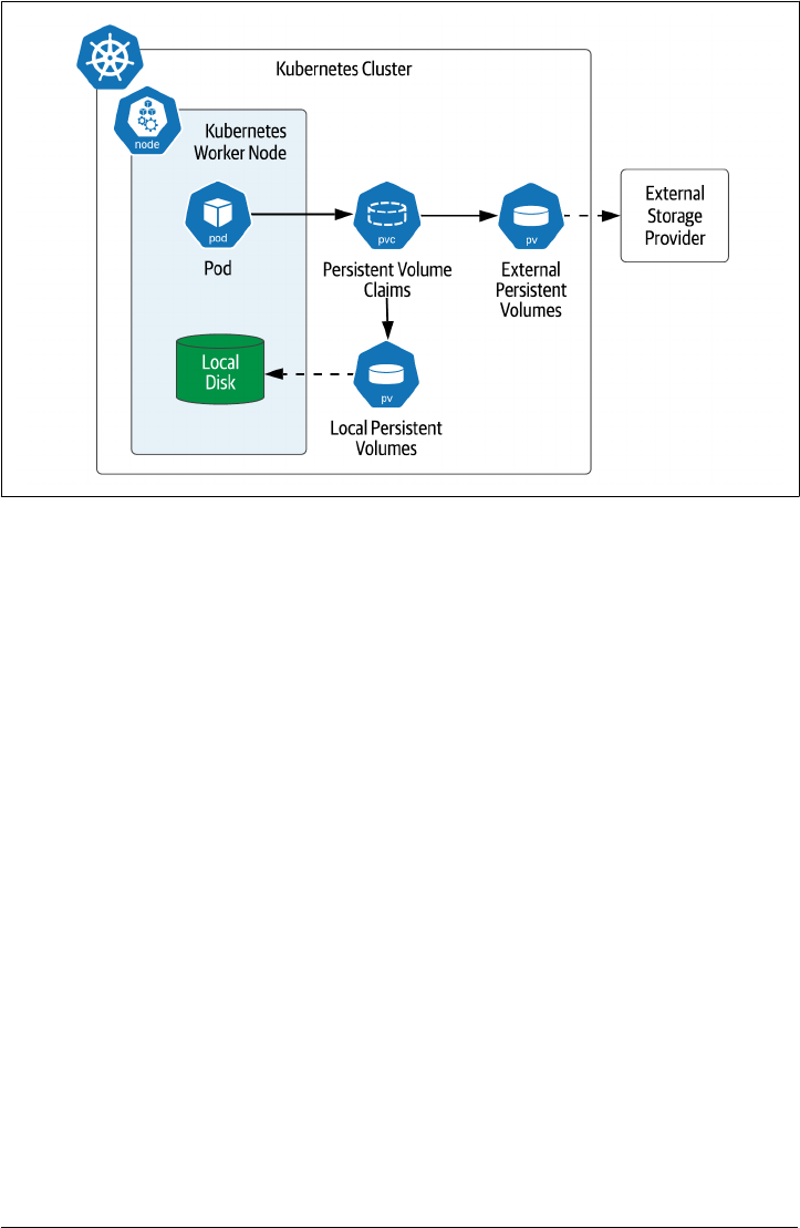
Figure 2-10. Accessing PersistentVolumes using PersistentVolumeClaims
Here’s what the process looks like from an application developer perspective. First,
you’ll create a PVC representing your desired storage criteria. For example, here’s a
claim that requests 1GB of storage with exclusive read/write access (source code):
apiVersion: v1
kind: PersistentVolumeClaim
metadata:
name: my-claim
spec:
storageClassName: ""
accessModes:
- ReadWriteOnce
resources:
requests:
storage: 1Gi
One interesting thing you may have noticed about this claim is that the storageClass
Name is set to an empty string. We’ll explain the significance of this when we discuss
StorageClasses below. You can reference the claim in the definition of a pod like this
(source code):
apiVersion: v1
kind: Pod
metadata:
name: my-pod
spec:
containers:
44 | Chapter 2: Managing Data Storage on Kubernetes

- name: nginx
image: nginx
volumeMounts:
- mountPath: "/app/data"
name: my-volume
volumes:
- name: my-volume
persistentVolumeClaim:
claimName: my-claim
As you can see, the PersistentVolume is represented within the pod as a volume. The
volume is given a name and a reference to the claim. This is considered to be a vol‐
ume of the persistentVolumeClaim type. As with other volumes, the volume is moun‐
ted into a container at a specific mount point, in this case into the main application
Nginx container at the path /app/data.
A PVC also has a state, which you can see if you retrieve the status:
Name: my-claim
Namespace: default
StorageClass:
Status: Bound
Volume: my-volume
Labels: <none>
Annotations: pv.kubernetes.io/bind-completed: yes
pv.kubernetes.io/bound-by-controller: yes
Finalizers: [kubernetes.io/pvc-protection]
Capacity: 3Gi
Access Modes: RWO
VolumeMode: Filesystem
Mounted By: <none>
Events: <none>
A PVC has one of two Status values: Bound, meaning it is bound to a volume (as is the
case above), or Pending, meaning that it has not yet been bound to a volume. Typi‐
cally a status of Pending means that no PV matching the claim exists.
Here’s what’s happening behind the scenes. Kubernetes uses the PVCs referenced as
volumes in a pod and takes those into account when scheduling the pod. Kubernetes
identifies PersistentVolumes that match properties associated with the claim and
binds the smallest available module to the claim. The properties might include a label,
or node affinity, as we saw above for local volumes.
When starting up a pod, the Kubernetes control plane makes sure the PersistentVo‐
lumes are mounted to the worker node. Then each requested storage volume is
mounted into the pod at the specified mount point.
Kubernetes Resources for Data Storage | 45
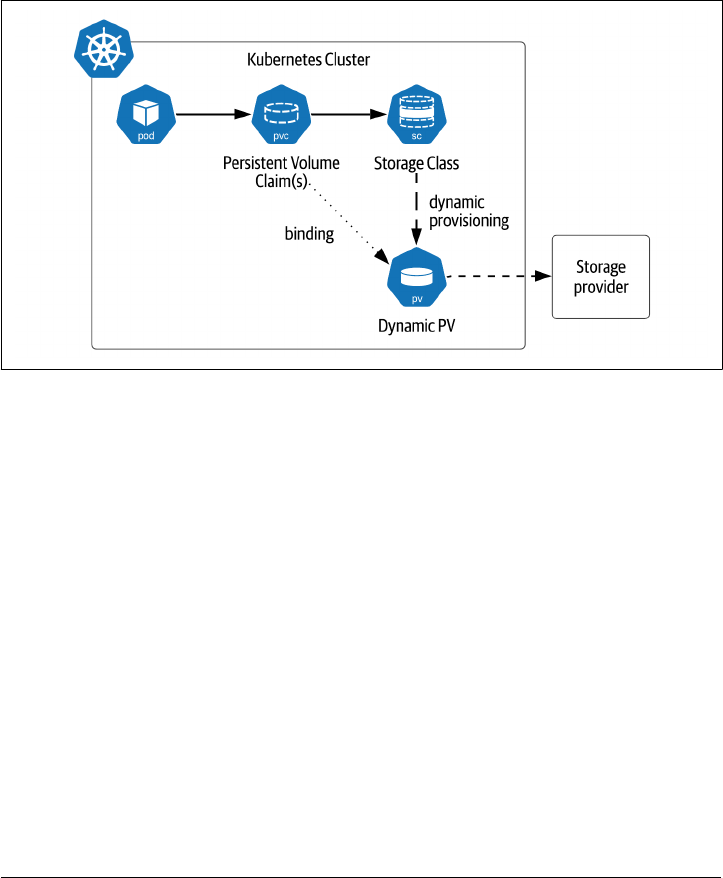
StorageClasses
The example shown above demonstrates how Kubernetes can bind PVCs to Persis‐
tentVolumes that already exist. This model in which PersistentVolumes are explicitly
created in the Kubernetes cluster is known as static provisioning. The Kubernetes
Persistent Volume Subsystem also supports dynamic provisioning of volumes using
StorageClasses (often abbreviated SC). The StorageClass is responsible for provision‐
ing (and deprovisioning) PersistentVolumes according to the needs of applications
running in the cluster, as shown in Figure 2-11.
Figure 2-11. StorageClasses support dynamic provisioning of volumes
Depending on the Kubernetes cluster you are using, it is likely that there is already at
least one StorageClass available. You can verify this using the command kubectl get
sc. If you’re running a simple Kubernetes distribution on your local machine and
don’t see any StorageClasses, you can install an open source local storage provider
from Rancher with the following command:
kubectl apply -f https://raw.githubusercontent.com/rancher/local-path-provisioner/master/deploy/local-path-storage.yaml
This storage provider comes pre-installed in K3s, a desktop distribution also pro‐
vided by Rancher. If you take a look at the YAML configuration referenced in that
statement, you’ll see the following definition of a StorageClass (source code):
apiVersion: storage.k8s.io/v1
kind: StorageClass
metadata:
name: local-path
provisioner: rancher.io/local-path
volumeBindingMode: WaitForFirstConsumer
reclaimPolicy: Delete
46 | Chapter 2: Managing Data Storage on Kubernetes

As you can see from the definition, a StorageClass is defined by a few key attributes:
• The provisioner interfaces with an underlying storage provider such as a public
cloud or storage system in order to allocate the actual storage. The provisioner
can either be one of the Kubernetes built-in provisioners (referred to as “in-tree”
because they are part of the Kubernetes source code), or a provisioner that con‐
forms to the Container Storage Interface (CSI), which we’ll examine below.
• The parameters are specific configuration options for the storage provider that
are passed to the provisioner. Common options include filesystem type, encryp‐
tion settings, and throughput in terms of IOPS. Check the documentation for the
storage provider for more details.
•
The reclaimPolicy describes whether storage is reclaimed when the Persistent‐
Volume is deleted. The default is Delete, but can be overridden to Retain, in
which case the storage administrator would be responsible for managing the
future state of that storage with the storage provider.
• Although it is not shown in the example above, there is also an optional allowVo
lumeExpansion flag. This indicates whether the StorageClass supports the ability
for volumes to be expanded. If true, the volume can be expanded by increasing
the size of the storage.request field of the PersistentVolumeClaim. This value
defaults to false.
•
The volumeBindingMode controls when the storage is provisioned and bound. If
the value is Immediate, a PersistentVolume is immediately provisioned as soon as
a PersistentVolumeClaim referencing the StorageClass as created, and the claim
is bound to the PersistentVolume, regardless of whether the claim is referenced
in a pod. Many storage plugins also support a second mode known as WaitFor
FirstConsumer, in which case no PersistentVolume is not provisioned until a pod
is created that references the claim. This behavior is considered preferable since it
gives the Kubernetes scheduler more flexibility.
Note: Limits on dynamic provisioning
Local cannot be dynamically provisioned by a StorageClass, so you
must create them manually yourself.
Application developers can reference a specific StorageClass when creating a PVC by
adding a storageClass property to the definition. For example, here is a YAML config‐
uration for a PVC referencing the local-path StorageClass (source code):
apiVersion: v1
kind: PersistentVolumeClaim
metadata:
Kubernetes Resources for Data Storage | 47

name: my-local-path-claim
spec:
storageClassName: local-path
accessModes:
- ReadWriteOnce
resources:
requests:
storage: 1Gi
If no storageClass is specified in the claim, then the default StorageClass is used. The
default StorageClass can be set by the cluster administrator. As we showed above in
the Persistent Volumes section, you can opt out of using StorageClasses by using the
empty string, which indicates that you are using statically provisioned storage.
StorageClasses provide a useful abstraction that cluster administrators and applica‐
tion developers can use as a contract: administrators define the StorageClasses, and
developers reference the StorageClasses by name. The details of the underlying Stora‐
geClass implementation can differ across Kubernetes platform providers, promoting
portability of applications.
This flexibility allows administrators to create StorageClasses representing a variety of
different storage options, for example, to distinguish between different quality of ser‐
vice guarantees in terms of throughput or latency. This concept is known as “profiles”
in other storage systems. See How Developers are Driving the Future of Kubernetes
Storage (sidebar) for more ideas on how StorageClasses can be leveraged in innova‐
tive ways.
Kubernetes Storage Architecture
In the preceding sections we’ve discussed the various storage resources that Kuber‐
netes supports via its API. In the remainder of the chapter, we’ll take a look at how
these solutions are constructed, as they can give us some valuable insights on how to
construct cloud-native data solutions.
Note: Defining Cloud-native storage
Most of the storage technologies we discuss in this chapter are cap‐
tured as part of the “cloud-native storage” solutions listed in Cloud
Native Computing Foundation (CNCF) landscape. The CNCF
Storage Whitepaper is a helpful resource which defines key terms
and concepts for cloud native storage. Both of these resources are
updated regularly.
48 | Chapter 2: Managing Data Storage on Kubernetes

Flexvolume
Originally, the Kubernetes codebase contained multiple “in-tree” storage plugins, that
is, included in the same GitHub repo as the rest of the Kubernetes code. The advan‐
tage of this was that it helped standardize the code for connecting to different storage
platforms, but there were a couple of disadvantages as well. First, many Kubernetes
developers had limited expertise across the broad set of included storage providers.
More significantly, the ability to upgrade storage plugins was tied to the Kubernetes
release cycle, meaning that if you needed a fix or enhancement for a storage plugin,
you’d have to wait until it was accepted into a Kubernetes release. This slowed the
maturation of storage technology for K8s, and as a result, adoption slowed as well.
The Kubernetes community created the Flexvolume specification to allow develop‐
ment of plugins that could be developed independently, that is, out of the Kubernetes
source code tree, without being tied to the Kubernetes release cycle. Around the same
time, storage plugin standards were emerging for other container orchestration sys‐
tems, and developers from these communities began to question the wisdom of
developing multiple standards to solve the same basic problem.
Note: Future Flexvolume support
While new feature development has paused on Flexvolume, many
deployments still rely on these plugins, and there are no active
plans to deprecate the feature as of the Kubernetes 1.21 release.
Container Storage Interface (CSI)
The Container Storage Interface (CSI) initiative was established as an industry stan‐
dard for storage for containerized applications. CSI is an open standard used to
define plugins that will work across container orchestration systems including Kuber‐
netes, Mesos, and Cloud Foundry. As Saad Ali, Google engineer and chair of the
Kubernetes Storage Special Interest Group (SIG), noted in The New Stack article The
State of State in Kubernetes: “The Container Storage Interface allows Kubernetes to
interact directly with an arbitrary storage system.”
The CSI specification is available on GitHub. Support for the CSI in Kubernetes
began with the 1.x release and it went GA in the 1.13 release. Kubernetes continues to
track updates to the CSI specification.
Once a CSI implementation is deployed on a Kubernetes cluster, its capabilities are
accessed through the standard Kubernetes storage resources such as PVCs, PVs, and
SCs. On the backend, each CSI implementation must provide two plugins: a node
plugin and a controller plugin. The CSI specification defines required interfaces for
these plugins using gRPC but does not specify exactly how the plugins are to be
deployed.
Kubernetes Storage Architecture | 49
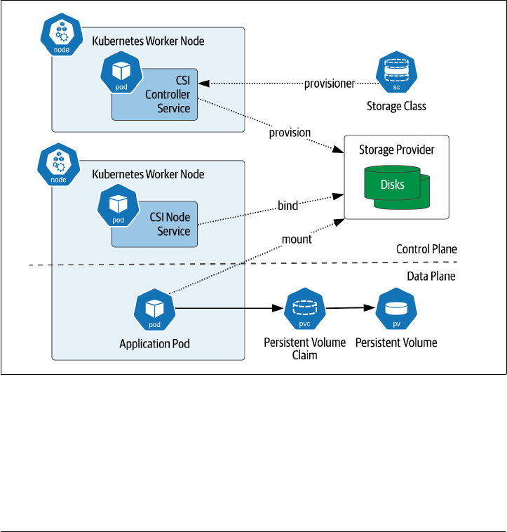
Let’s briefly look at the role of each of these services, also depicted in Figure 2-12:
• The controller plugin supports operations on volumes such as create, delete, list‐
ing, publishing/unpublishing, tracking and expanding volume capacity. It also
tracks volume status including what nodes each volume is attached to. The con‐
troller plugin is also responsible for taking and managing snapshots, and using
snapshots to clone a volume. The controller plugin can run on any node - it is a
standard Kubernetes controller.
• The node plugin runs on each Kubernetes worker node where provisioned vol‐
umes will be attached. The node plugin is responsible for local storage, as well as
mounting and unmounting volumes onto the node. The Kubernetes control
plane directs the plugin to mount a volume prior to any pods being scheduled on
the node that require the volume.
Figure 2-12. Container Storage Interface mapped to Kubernetes
50 | Chapter 2: Managing Data Storage on Kubernetes

Note: Additional CSI resources:
The CSI documentation site provides guidance for developers and
storage providers who are interested in developing CSI-compliant
drivers. The site also provides a very useful list of CSI-compliant
drivers. This list is generally more up to date than one provided on
the Kubernetes documentation site.
Sidebar: CSI Migration
The Kubernetes community has been very conscious of preserving forward and back‐
ward compatibility between versions, and the transition from in-tree storage plugins
to the CSI is no exception. Features in Kubernetes are typically introduced as Alpha
features, and progress to Beta, before being released as General Availability (GA). The
introduction of a new API such as the CSI presents a more complex challenge
because it involves the introduction of a new API as well as the deprecation of older
APIs.
The CSI migration approach was introduced in order to promote a coherent experi‐
ence for users of storage plugins. The implementation of each corresponding in-tree
plugin is changed to a facade when an equivalent CSI-compliant driver becomes
available. Calls on the in-tree plugin are delegated to the underlying CSI-compliant
driver. The migration capability is itself a feature that can be enabled on a Kubernetes
cluster.
This allows a staged adoption process that can be used as existing clusters are updated
to newer Kubernetes versions. Each application can be updated independently to use
CSI-compliant drivers instead of in-tree drivers. This approach to maturing and
replacing APIs is a helpful pattern for promoting stability of the overall platform and
providing administrators control over their migration to the new API.
Container Attached Storage
While the CSI is an important step forward in standardizing storage management
across container orchestrators, it does not provide implementation guidance on how
or where the storage software runs. Some CSI implementations are basically thin
wrappers around legacy storage management software running outside of the Kuber‐
netes cluster. While there are certainly benefits to this reuse of existing storage assets,
many developers have expressed a desire for storage management solutions that run
entirely in Kubernetes alongside their applications.
Container Attached Storage is a design pattern which provides a more cloud-native
approach to managing storage. The business logic to manage storage operations such
as attaching volumes to applications is itself composed of microservices running in
containers. This allows the storage layer to have the same properties as other applica‐
tions deployed on Kubernetes and reduces the number of different management
Kubernetes Storage Architecture | 51

interfaces administrators have to keep track of. The storage layer becomes just
another Kubernetes application.
As Evan Powell noted in his article on the CNCF Blog, Container Attached Storage: A
primer, “Container Attached Storage reflects a broader trend of solutions that rein‐
vent particular categories or create new ones – by being built on Kubernetes and
microservices and that deliver capabilities to Kubernetes based microservice environ‐
ments. For example, new projects for security, DNS, networking, network policy
management, messaging, tracing, logging and more have emerged in the cloud-native
ecosystem.”
There are several examples of projects and products that embody the CAS approach
to storage. Let’s examine a few of the open-source options.
OpenEBS
OpenEBS is a project created by MayaData and donated to the CNCF, where it
became a sandbox project in 2019. The name is a play on Amazon’s Elastic Block
Store, and OpenEBS is an attempt to provide an open source equivalent to this
popular managed service. OpenEBS provides storage engines for managing both
local and NVMe PersistentVolumes.
OpenEBS provides a great example of a CSI-compliant implementation deployed
onto Kubernetes, as shown in Figure 2-13. The control plane includes the Open‐
EBS provisioner, which implements the CSI controller interface, and the Open‐
EBS API server, which provides a configuration interface for clients and interacts
with the rest of the Kubernetes control plane.
The Open EBS data plane consists of the Node Disk Manager (NDM) as well as
dedicated pods for each PersistentVolume. The NDM runs on each Kubernetes
worker where storage will be accessed. It implements the CSI node interface and
provides the helpful functionality of automatically detecting block storage devi‐
ces attached to a worker node.
52 | Chapter 2: Managing Data Storage on Kubernetes
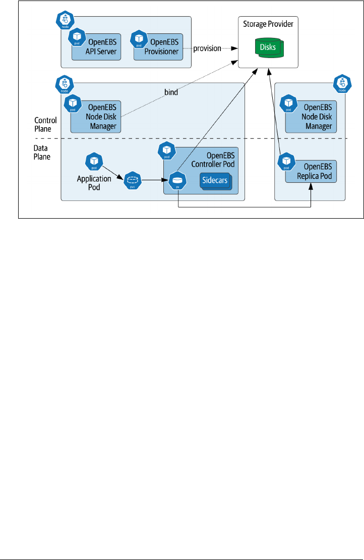
Figure 2-13. OpenEBS Architecture
OpenEBS creates multiple pods for each volume. A controller pod is created as
the primary replica, and additional replica pods are created on other Kubernetes
worker nodes for high availability. Each pod includes sidecars that expose inter‐
faces for metrics collection and management, which allows the control plane to
monitor and manage the data plane.
Longhorn
Longhorn is an open-source, distributed block storage system for Kubernetes. It
was originally developed by Rancher, and became a CNCF sandbox project in
2019. Longhorn focuses on providing an alternative to cloud-vendor storage and
expensive external storage arrays. Longhorn supports providing incremental
backups to NFS or AWS S3 compatible storage, and live replication to a separate
Kubernetes cluster for disaster recovery.
Longhorn uses a similar architecture to that shown for OpenEBS; according to
the documentation, “Longhorn creates a dedicated storage controller for each
block device volume and synchronously replicates the volume across multiple
replicas stored on multiple nodes. The storage controller and replicas are them‐
selves orchestrated using Kubernetes.” Longhorn also provides an integrated user
interface to simplify operations.
Rook and Ceph
According to its website, “Rook is an open source cloud-native storage orchestra‐
tor, providing the platform, framework, and support for a diverse set of storage
Kubernetes Storage Architecture | 53

solutions to natively integrate with cloud-native environments.” Rook was origi‐
nally created as a containerized version of Ceph that could be deployed in Kuber‐
netes. Ceph is an open-source distributed storage framework that provides block,
file, and object storage. Rook was the first storage project accepted by the CNCF
and is now considered a CNCF Graduated project.
Rook is a truly Kubernetes-native implementation in the sense that it makes use
of Kubernetes custom resources (CRDs) and custom controllers called operators.
Rook provides operators for Ceph, Apache Cassandra, and Network File System
(NFS). We’ll learn more about custom resources and operators in Chapter 4.
There are also commercial solutions for Kubernetes that embody the CAS pattern.
These include MayaData (creators of OpenEBS), Portworx by PureStorage, Robin.io,
and StorageOS. These companies provide both raw storage in block and file formats,
as well as integrations for simplified deployments of additional data infrastructure
such as databases and streaming solutions.
Container Object Storage Interface (COSI)
The CSI provides support for file and block storage, but object storage APIs require
different semantics and don’t quite fit the CSI paradigm of mounting volumes. In Fall
2020, a group of companies led by MinIO began work on a new API for object stor‐
age in container orchestration platforms: the Container Object Storage Interface
(COSI). COSI provides a Kubernetes API more suited to provisioning and accessing
object storage, defining a bucket custom resource and including operations to create
buckets and manage access to buckets. The design of the COSI control plane and data
plane is modeled after the CSI. COSI is an emerging standard with a great start and
potential for wide adoption in the Kubernetes community and potentially beyond.
Sidebar: How Developers are Driving the Future of Kubernetes Storage
With Kiran Mova, co-founder and CTO of MayaData, member of Kubernetes Storage
Special Interest Group (SIG)
Many organizations are just starting their containerization journey. Kubernetes is the
shiny object, and everybody wants to run everything in Kubernetes. But not all teams
are ready for Kubernetes, much less managing stateful workloads on Kubernetes.
Application developers are the ones driving the push for stateful workloads on Kuber‐
netes. These developers get started with cloud resources that are available to them,
even a single node Kubernetes cluster, and assume they’re ready to run that in pro‐
duction. Developers are “Kuberneticizing” their in-house applications, and the
demands on storage are quite different from what the platform teams that support
them are used to.
54 | Chapter 2: Managing Data Storage on Kubernetes

Microservices and Kubernetes have changed the way storage volumes are provi‐
sioned. Platform teams are used to thinking about data in terms of provisioning vol‐
umes with the required throughput or capacity. In the old way, the platform team
would meet with the application team, estimate the size of the data, do a month of
planning, provision a 2-3 TB volume, and mount it into the VMs or bare metal
servers and that would provide enough storage capacity for the next year.
With Kubernetes, provisioning has become much easier and ad-hoc. You can run
things in a very cost effective and agile way by adopting Kubernetes. But many plat‐
form teams are still working to catch up. Some teams are simply focused on provi‐
sioning storage correctly, while others are beginning to focus on “day 2” operations,
such as automated provisioning, expanding volumes, or disconnecting and destroy‐
ing volumes.
Platform teams don’t yet have a foolproof way to run stateful workloads in Kuber‐
netes, so they often offload persistence to public cloud providers. The public clouds
make a strong case for their managed services, claiming they have everything that
you’ll need to run a storage system, but once you start using managed services for
state, you can become dependent on those cloud providers and get stuck.
Meanwhile, there are innovations in storage technology happening in parallel:
The landscape is shifting back and forth between hyperconverged and disaggregated.
This re-architecture is happening at all the layers of the stack, and it’s not just the soft‐
ware, it includes processes and the people who consume the data.
Hardware trends are driving toward low-latency solutions including NVMe and
DPDK/SPDK, and changes to the Linux kernel like io_uring to take advantage of
faster hardware.
Container attached storage will help us manage storage more effectively. For example,
being able to reclaim storage space when workloads shrink. This can be a difficult
problem with data distributed across multiple nodes. We’ll need better logic for relo‐
cating data onto existing nodes.
Technologies that bring more automation for compliance and operations are coming
into the picture as well.
With all these innovations, it can be a bit overwhelming to understand the big picture
and determine how to leverage this technology for maximum benefit. Platform SREs
need to learn about Kubernetes, declarative deployments, GitOps principles, new vol‐
ume types, and even database concepts like eventual consistency.
We envision a future in which application developers will specify their Kubernetes
storage needs in terms of the required quality of service, such as I/O operations per
second (IOPS) and throughput. Developers should be able to specify different storage
needs for their workloads in more human-relatable terms. For example, platform
teams could define StorageClasses for “fast storage” vs “slow storage”, or perhaps
“metadata storage” vs “data storage”. These StorageClasses will make different cost/
Kubernetes Storage Architecture | 55

performance tradeoffs and provide specific service level agreements (SLAs). We may
even see some standard definitions start to emerge for these new StorageClasses.
Ideally, application teams should not be picking into what storage solutions are
chosen. The only thing an application developer should be concerned with is specify‐
ing PersistentVolumeClaims for their application, with the StorageClasses they need.
The other details of managing storage should be hidden, although of course the stor‐
age subsystem will report errors including status and logs via the standard Kubernetes
mechanisms. This capability will make things a lot simpler for application developers,
whether they’re deploying a database, or some other stateful workload.
These innovations will guide us to a more optimal place with storage on Kubernetes.
Today we’re in a place where deploying infrastructure is easy. Let’s work together to
get to a place where deploying the right infrastructure is easy.
As you can see, storage on Kubernetes is an area in which there is a lot of innovation,
including multiple open source projects and commercial vendors competing to pro‐
vide the most usable, cost effective, and performant solutions. The Cloud-Native
Storage section of the CNCF Landscape provides a helpful listing of storage providers
and related tools, including the technologies referenced in this chapter and many
more.
Summary
In this chapter, we’ve explored how persistence is managed in container systems like
Docker, and container orchestration systems like Kubernetes. You’ve learned about
the various Kubernetes resources that can be used to manage stateful workloads,
including Volumes, PersistentVolumes, PersistentVolumeClaims, StorageClasses.
We’ve seen how the Container Storage Interface and Container Attached Storage pat‐
tern point the way toward more cloud-native approaches to managing storage. Now
you’re ready to learn how to use these building blocks and design principles to man‐
age stateful workloads including databases, streaming data, and more.
56 | Chapter 2: Managing Data Storage on Kubernetes

CHAPTER 3
Databases on Kubernetes the Hard Way
A Note for Early Release Readers
With Early Release ebooks, you get books in their earliest form—the author’s raw and
unedited content as they write—so you can take advantage of these technologies long
before the official release of these titles.
This will be the 3rd chapter of the final book. Please note that the GitHub repo will be
made active later on.
If you have comments about how we might improve the content and/or examples in
this book, or if you notice missing material within this chapter, please reach out to the
authors at [email protected] (Jeff Carpenter) and [email protected] (Pat‐
rick McFadin).
As we discussed in Chapter 1, Kubernetes was designed for stateless workloads. A
corollary to this is that stateless workloads are what Kubernetes does best. Because of
this, some have argued that you shouldn’t try to run stateful workloads on Kuber‐
netes, and you may hear various recommendations about what you should do
instead: “use a managed service”, or “leave data in legacy databases in your on-
premises data center”, or perhaps even “run your databases in the cloud, but in tradi‐
tional VMs instead of containers.”
While these recommendations are still viable options, one of our main goals in this
book is to demonstrate that running data infrastructure in Kubernetes has become
not only a viable option, but a preferred option. In his article, A Case for Databases
on Kubernetes from a Former Skeptic, Chris Bradford describes his journey from
being skeptical of running any stateful workload in Kubernetes, to grudging accept‐
ance of running data infrastructure on Kubernetes for development and test work‐
57

loads, to enthusiastic evangelism around deploying databases on K8s in production.
This journey is typical of many in the Data on Kubernetes community. By the middle
of 2020, Boris Kurktchiev was able to cite a growing consensus that managing stateful
workloads on Kubernetes had reached a point of viability, and even maturity, in his
article 3 Reasons to Bring Stateful Applications to Kubernetes.
How did this change come about? Over the past several years, the Kubernetes com‐
munity has shifted focus toward adding features that support the ability to manage
state in a cloud-native way on Kubernetes. The storage elements represent a big part
of this shift we introduced in the previous chapter, including the Kubernetes Persis‐
tentVolume subsystem and the adoption of the Container Storage Interface. In this
chapter, we’ll complete this part of the story by looking at Kubernetes resources for
building stateful applications on top of this storage foundation. We’ll focus in particu‐
lar on a specific type of stateful application: data infrastructure.
The Hard Way
The phrase “doing it the hard way” has come to be associated with avoiding the easy
option in favor of putting in the detailed work required to accomplish a result that
will have lasting significance. Throughout history, pioneers of all persuasions are well
known for taking pride in having made the sacrifice of blood, sweat, and tears that
make life just that little bit more bearable for the generations that follow. These elders
are often heard to lament when their proteges fail to comprehend the depth of what
they had to go through.
In the tech world it’s no different. While new innovations such as APIs and “no code”
environments have massive potential to grow a new crop of developers worldwide, it
is still the case that a deeper understanding of the underlying technology is required
in order to manage highly available and secure systems at worldwide scale. It’s when
things go wrong that this detailed knowledge proves its worth. This is why many of us
who are software developers and never touch a physical server in our day jobs gain so
much from building our own PC by wiring chips and boards by hand. It’s also one of
the hidden benefits of serving as informal IT consultants for our friends and family.
For the Kubernetes community, of course, “the hard way” has an even more specific
connotation. Google engineer Kelsey Hightower’s Kubernetes the Hard Way has
become a sort of rite of passage for those who want a deeper understanding of the
elements that make up a Kubernetes cluster. This popular tutorial walks you through
downloading, installing, and configuring each of the components that make up the
Kubernetes control plane. The result is a working Kubernetes cluster, which, although
not suitable for deploying a production workload, is certainly functional enough for
development and learning. The appeal of the approach is that all of the instructions
are typed by hand instead of downloading a bunch of scripts that do everything for
you, so that you understand what is happening at each step.
58 | Chapter 3: Databases on Kubernetes the Hard Way

In this chapter, we’ll emulate this approach and walk you through deploying some
example data infrastructure the hard way ourselves. Along the way, we’ll get more
hands-on experience with the storage resources you learned about in Chapter 2, and
we’ll introduce additional Kubernetes resource types for managing compute and net‐
work to complete the “Compute, Network, Storage” triad we introduced in Chapter 1.
Are you ready to get your hands dirty? Let’s go!
Warning: Examples are Not Production-Grade
The examples we present in this chapter are primarily for introduc‐
ing new elements of the Kubernetes API and are not intended to
represent deployments we’d recommend running in production.
We’ll make sure to highlight where there are gaps so that we can
demonstrate how to fill them in upcoming chapters.
Prerequisites for running data infrastructure on
Kubernetes
To follow along with the examples in this chapter, you’ll want to have a Kubernetes
cluster to work on. If you’ve never tried it before, perhaps you’ll want to build a clus‐
ter using the Kubernetes the Hard Way instructions, and then use that same cluster to
add data infrastructure the hard way as well. You could also use a simple desktop K8s
as well, since we won’t be using a large amount of resources. If you’re using a shared
cluster, you might want to install these examples in their own namespace to isolate
them from the work of others.
kubectl config set-context --current --namespace=<insert-namespace-name-here>
You’ll also need to make sure you have a StorageClass in your cluster. If you’re start‐
ing from a cluster built the hard way, you won’t have one. You may want to follow the
instructions in the section StorageClasses for installing a simple StorageClass and
provisioner that expose local storage (source code).
You’ll want to use a StorageClass that supports a volumeBindingMode of WaitFor
FirstConsumer. This gives Kubernetes the flexibility to defer provisioning storage
until we need it. This behavior is generally preferred for production deployments, so
you might as well start getting in the habit.
Running MySQL on Kubernetes
First, let’s start with a super simple example. MySQL is one of the most widely used
relational databases due to its reliability and usability. For this example we’ll build on
the MySQL tutorial in the official Kubernetes documentation, with a couple of twists.
You can find the source code used in this section at Deploying MySQL Example -
Prerequisites for running data infrastructure on Kubernetes | 59
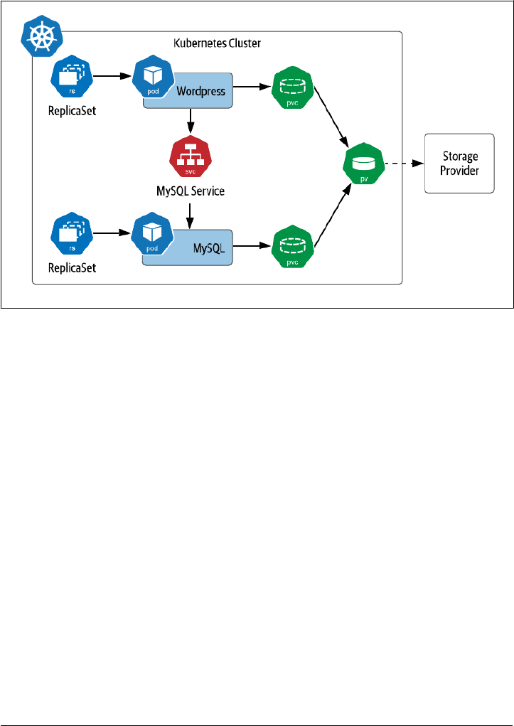
Data on Kubernetes the Hard Way. The tutorial includes two Kubernetes deploy‐
ments: one to run MySQL pod, and another to run a sample client, in this case
Wordpress. This configuration is shown in Figure 3-1.
Figure 3-1. Sample Kubernetes Deployment of MySQL
In this example, we see that there is a PersistentVolumeClaim for each pod. For the
purposes of this example, we’ll assume these claims are satisfied by a single volume
provided by the default StorageClass. You’ll also notice that each pod is shown as part
of a ReplicaSet and that there is a service exposed for the MySQL database. Let’s take a
pause and introduce these concepts.
ReplicaSets
Production application deployments on Kubernetes do not typically deploy individ‐
ual pods, because an individual pod could easily be lost when the node disappears.
Instead, pods are typically deployed in the context of a Kubernetes resource that
manages their lifecycle. ReplicaSet is one of these resources, and the other is Stateful‐
Set, which we’ll look at later in the chapter.
The purpose of a ReplicaSet (RS) is to ensure that a specified number of replicas of a
given pod are kept running at any given time. As pods are destroyed, others are cre‐
ated to replace them in order to satisfy the desired number of replicas. A ReplicaSet is
defined by a pod template, a number of replicas, and a selector. The pod template
defines a specification for pods that will be managed by the ReplicaSet, similar to
60 | Chapter 3: Databases on Kubernetes the Hard Way

what we saw for individual pods created in the examples in Chapter 2. The number of
replicas can be 0 or more. The selector identifies pods that are part of the ReplicaSet.
Let’s look at a portion of an example definition of a ReplicaSet for the Wordpress
application shown in Figure 3-1:
apiVersion: apps/v1
kind: ReplicaSet
metadata:
name: wordpress-mysql
labels:
app: wordpress
spec:
replicas: 1
selector:
matchLabels:
app: wordpress
tier: mysql
template:
metadata:
labels:
app: wordpress
tier: mysql
spec:
containers:
- image: mysql:5.6
name: mysql
...
A ReplicaSet is responsible for creating or deleting pods in order to meet the specified
number of replicas. You can scale the size of a RS up or down by changing this value.
The pod template is used when creating new pods. Pods that are managed by a Repli‐
caSet contain a reference to the RS in their metadata.ownerReferences field. A Rep‐
licaSet can actually take responsibility for managing a pod that it did not create if the
selector matches and the pod does not reference another owner. This behavior of a
ReplicaSet is known as acquiring a pod.
You might be wondering why we didn’t provide a full definition of a ReplicaSet above.
As it turns out, most application developers do not end up using ReplicaSets directly,
because Kubernetes provides another resource type that manages ReplicaSets declara‐
tively: Deployments.
Running MySQL on Kubernetes | 61
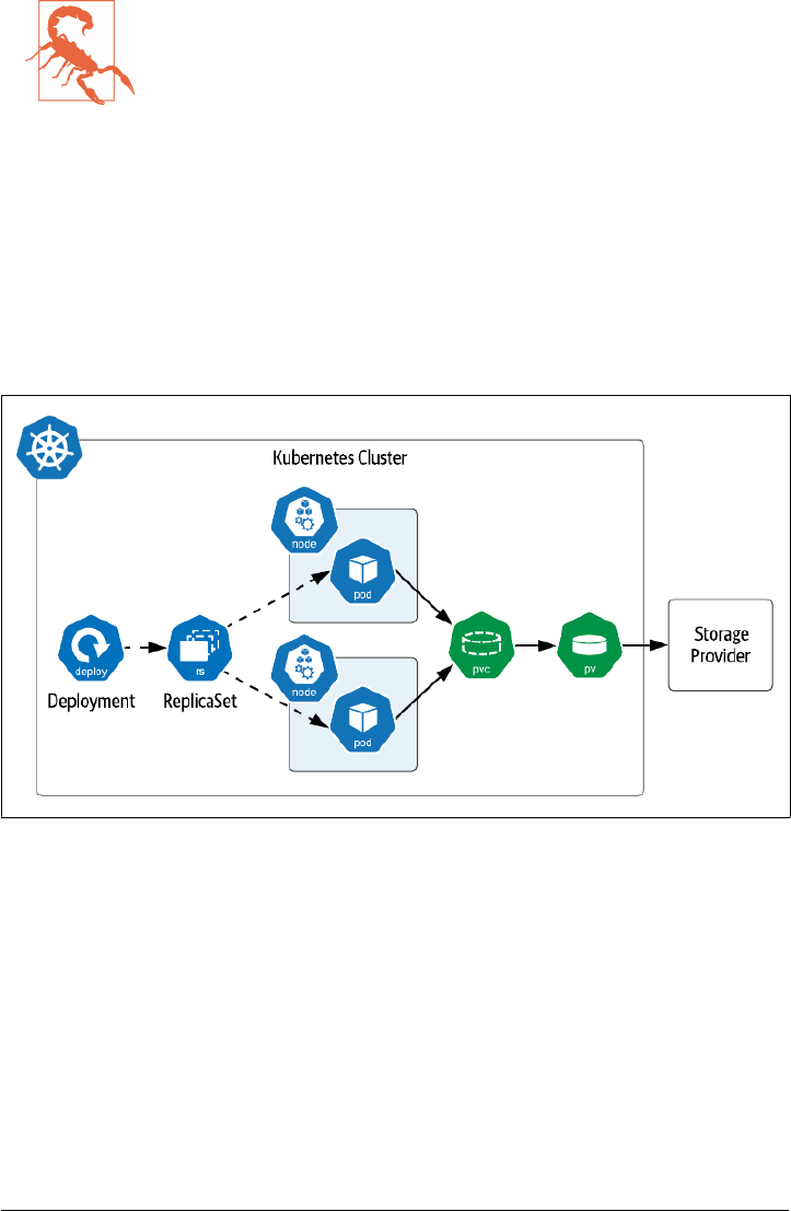
Warning: Define ReplicaSet selectors carefully
If you do create ReplicaSets directly, make sure that the selector
you use is unique and does not match any bare pods that you do
not intend to be acquired. It is possible that pods that do not match
the pod template can be acquired if the selectors match.
For more information about managing the lifecycle of ReplicaSets
and the pods they manage, see the Kubernetes documentation.
Deployments
A Kubernetes Deployment is a resource which builds on top of ReplicaSets with addi‐
tional features for lifecycle management, including the ability to rollout new versions
and rollback to previous versions. As shown in Figure 3-2, creating a Deployment
results in the creation of a ReplicaSet as well.
Figure 3-2. Deployments and ReplicaSets
This figure highlights that ReplicaSets (and therefore the Deployments that manage
them) operate on cloned replicas of pods, meaning that the definitions of the pods are
the same, even down to the level of PersistentVolumeClaims. The definition of a Rep‐
licaSet references a single PVC that is provided to it, and there is no mechanism pro‐
vided to clone the PVC definition for additional pods. For this reason, Deployments
and ReplicaSets are not a good choice if your intent is that each pod have access to its
own dedicated storage.
Deployments are a good choice if your application pods do not need access to stor‐
age, or if your intent is that they access the same piece of storage. However, the cases
62 | Chapter 3: Databases on Kubernetes the Hard Way

where this would be desirable are pretty rare, since you likely don’t want a situation in
which you could have multiple simultaneous writers to the same storage.
Let’s create an example Deployment. First, create a secret that will represent the data‐
base password (substitute in whatever string you want for the password):
kubectl create secret generic mysql-root-password --from-literal=password=<your password>
Next, create a PVC that represents the storage that the database can use (source
code). A single PVC is sufficient in this case since you are creating a single node. This
should work as long as you have an appropriate storage class as referenced earlier.
apiVersion: v1
kind: PersistentVolumeClaim
metadata:
name: mysql-pv-claim
labels:
app: wordpress
spec:
accessModes:
- ReadWriteOnce
resources:
requests:
storage: 1Gi
Next, create a Deployment with a pod spec that runs MySQL (source code). Note that
it includes a reference to the PVC you just created as well as the Secret containing the
root password for the database.
apiVersion: apps/v1
kind: Deployment
metadata:
name: wordpress-mysql
labels:
app: wordpress
spec:
selector:
matchLabels:
app: wordpress
tier: mysql
strategy:
type: Recreate
template:
metadata:
labels:
app: wordpress
tier: mysql
spec:
containers:
- image: mysql:5.7
name: mysql
env:
Running MySQL on Kubernetes | 63

- name: MYSQL_ROOT_PASSWORD
valueFrom:
secretKeyRef:
name: mysql-root-password
key: password
ports:
- containerPort: 3306
name: mysql
volumeMounts:
- name: mysql-persistent-storage
mountPath: /var/lib/mysql
volumes:
- name: mysql-persistent-storage
persistentVolumeClaim:
claimName: mysql-pv-claim
There are a couple of interesting things to note about this Deployment’s specification.
• First, note that the Deployment has a Recreate strategy. This refers to how the
Deployment handles the replacement of pods when the pod template is updated,
and we’ll discuss this shortly.
• Next, note under the pod template that the password is passed to the pod as an
environment variable extracted from via the secret you created above. Overriding
the default password is an important aspect of securing any database deployment.
• Note also that a single port is exposed on the MySQL image for database access,
since this is a relatively simple example. In other samples in this book we’ll see
cases of pods that expose additional ports for administrative operations, metrics
collection, and more. The fact that access is disabled by default is a great feature
of Kubernetes.
• The MySQL image mounts a volume for its persistent storage using the PVC
defined above.
•
Finally, note that the number of replicas was not provided in the specification.
This means that the default value of 1 will be used.
After applying the configuration above, try using a command like kubectl get deploy
ments,rs,pods to check and see the items that Kubernetes created for you. You’ll
notice a single ReplicaSet named after the deployment that includes a random string,
for example: wordpress-mysql-655c8d9c54. The pod’s name references the name of
the ReplicaSet, adding some additional random characters, for example: wordpress-
mysql-655c8d9c54-tgswd. These names provide a quick way to identify the relation‐
ships between these resources.
Here are a few of the actions that a Deployment takes to manage the lifecycle of Rep‐
licaSets. In keeping with Kubernetes’ emphasis on declarative operations, most of
these are triggered by updating the specification of the Deployment:
64 | Chapter 3: Databases on Kubernetes the Hard Way

Initial rollout
When you create a Deployment, Kubernetes uses the specification you provide to
create a ReplicaSet. The process of creating this ReplicaSet and its pods is known
as a rollout. A rollout is also performed as part of a rolling update, as described
below.
Scaling up or down
When you update a Deployment to change the number of replicas, the underly‐
ing ReplicaSet is scaled up or down accordingly.
Rolling update
When you update the Deployment’s pod template, for example by specifying a
different container image for the pod, Kubernetes creates a new ReplicaSet based
on the new pod template. The way that Kubernetes manages the transition
between the old and new ReplicaSets is described by the Deployment’s
spec.strategy property, which defaults to a value called RollingUpdate. In a
rolling update, the new ReplicaSet is slowly scaled up by creating pods conform‐
ing to the new template, as the number of pods in the existing ReplicaSet is scaled
down. During this transition, the Deployment enforces a maximum and mini‐
mum number of pods, expressed as percentages, as set by the spec.strat
egy.rollingupdate.maxSurge and maxUnavailable properties. Each of these
values default to 25%.
Recreate update
The other strategy option for use when you update the pod template is Recreate.
This is the option that was set in the Deployment above. With this option, the
existing ReplicaSet is terminated immediately before the new ReplicaSet is cre‐
ated. This strategy is useful for development environments since it completes the
update more quickly, whereas RollingUpdate is more suitable for production
environments since it emphasises high availability.
Rollback update
It is possible that in creating or updating a Deployment you could introduce an
error, for example by updating a container image in a pod with a version that
contains a bug. In this case the pods managed by the Deployment might not even
initialize fully. You can detect these types of errors using commands such as
kubectl rollout status. Kubernetes provides a series of operations for manag‐
ing the history of rollouts of a Deployment. You can access these via kubectl
commands such as kubectl rollout history, which provides a numbered his‐
tory of rollouts for a deployment, and kubectl rollout undo, which reverts a
Deployment to the previous rollout. You can also undo to a specific rollout ver‐
sion with the --to-version option. Because kubectl supports rollouts for other
resource types we’ll cover below (StatefulSets and DaemonSets), you’ll need to
include the resource type and name when using these commands, for example:
Running MySQL on Kubernetes | 65

kubectl rollout history deployment/wordpress-mysql
Which produces output such as:
deployment.apps/wordpress-mysql
REVISION CHANGE-CAUSE
1 <none>
As you can see, Kubernetes Deployments provide some sophisticated behaviors
for managing the lifecycle of a set of cloned pods. You can test out these lifecycle
operations (other than rollback) by changing the Deployment’s YAML specifica‐
tion and re-applying it. Try scaling the number of replicas to 2 and back again, or
using a different MySQL image. After updating the Deployment, you can use a
command like kubectl describe deployment wordpress-mysql to observe the
events that Kubernetes initiates to bring your Deployment to your desired state.
There are other options available for Deployments which we don’t have space to go
into here, for example, how to specify what Kubernetes does if you attempt an update
that fails. For a more in-depth explanation of the behavior of Deployments, see the
Kubernetes documentation.
Services
In the steps above, you’ve created a PVC to specify the storage needs of the database,
a Secret to provide administrator credentials, and a Deployment to manage the lifecy‐
cle of a single MySQL pod. Now that you have a running database, you’ll want to
make it accessible to applications. In our scheme of compute, network, and storage
that we introduced in Chapter 1, this is the networking part.
Kubernetes Services are the primitive that we need to use to expose access to our
database as a network service. A Service provides an abstraction for a group of pods
running behind it. In the case of a single MySQL node as in this example, you might
wonder why we’d bother creating this abstraction. One key feature that a Service sup‐
ports is to provide a consistently named endpoint that doesn’t change. You don’t want
to be in a situation of having to update your clients whenever the database pod is
restarted and gets a new IP address. You can create a Service for accessing MySQL
using a YAML configuration like this (source code):
apiVersion: v1
kind: Service
metadata:
name: wordpress-mysql
labels:
app: wordpress
spec:
ports:
- port: 3306
selector:
66 | Chapter 3: Databases on Kubernetes the Hard Way

app: wordpress
tier: mysql
clusterIP: None
Here are a couple of things to note about this configuration:
•
First, this configuration specifies a port that is exposed on the Service: 3306. In
defining a service there are actually two ports involved: the port exposed to cli‐
ents of the Service, and the targetPort exposed by the underlying pods that the
Service is fronting. Since you haven’t specified a targetPort, it defaults to the
port value.
• Second, the selector defines what pods the Service will direct traffic to. In this
configuration, there will only be a single MySQL pod managed by the Deploy‐
ment, and that’s just fine.
•
Finally, if you have worked with Kubernetes Services before, you may note that
there is no serviceType defined for this service, which means that it is of the
default type, known as ClusterIP. Furthermore, since the clusterIP property is
set to None, this is what is known as a headless service, that is, a service where the
service’s DNS name is mapped directly to the IP addresses of the selected pods.
Kubernetes supports several types of services to address different use cases, which are
shown in Figure 3-3. We’ll introduce them briefly here in order to highlight their
applicability to data infrastructure:
ClusterIP Service
This type of Service is exposed on an IP address that is only accessible from
within the Kubernetes cluster. This is the type of service that you’ll see used most
often for data infrastructure such as databases in Kubernetes, especially headless
services, since this infrastructure is typically deployed in Kubernetes alongside
the application which uses it.
NodePort Service
A NodePort Service is exposed externally to the cluster on the IP address of each
worker node. A ClusterIP service is also created internally, to which the Node‐
Port routes traffic. You can allow Kubernetes to select what external port is used,
or specify the one you desire using the NodePort property. NodePort services are
most suitable for development environments, when you need to debug what is
happening on a specific instance of a data infrastructure application.
LoadBalancer
LoadBalancer services represent a request from the Kubernetes runtime to set up
a load balancer provided by the underlying cloud provider. For example, on
Amazon’s Elastic Kubernetes Service (EKS), requesting a LoadBalancer service
causes an instance of an Elastic Load Balancer (ELB) to be created. Usage of
Running MySQL on Kubernetes | 67
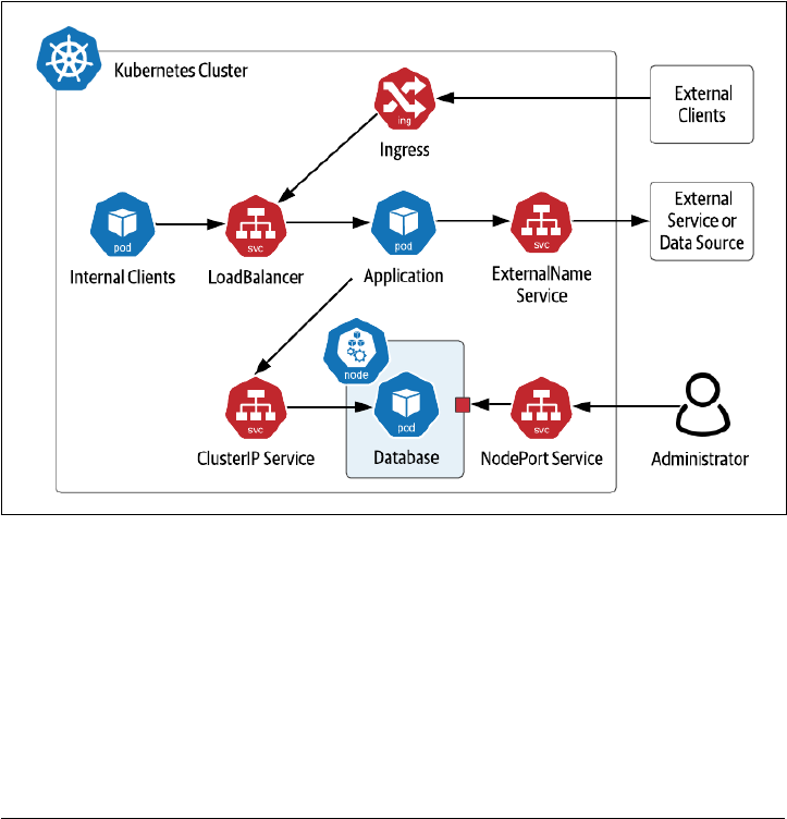
LoadBalancers in front of multi-node data infrastructure deployments is typically
not required, as these data technologies often have their own approaches for dis‐
tributing load. For example, Apache Cassandra drivers are aware of the topology
of a Cassandra cluster and provide load balancing features to client applications,
eliminating the need for a load balancer.
ExternalName Service
An ExternalName Service is typically used to represent access to a service that is
outside your cluster, for example a database that is running externally to Kuber‐
netes. An ExternalName service does not have a selector as it is not mapping to
any pods. Instead, it maps the Service name to a CNAME record. For example, if
you create a my-external-database service with an externalName of data
base.mydomain.com, references in your application pods to my-external-database
will be mapped to database.mydomain.com.
Figure 3-3. Kubernetes Service Types
Note also the inclusion of Ingress in the figure. While Kubernetes Ingress is not a type
of Service, it is related. An Ingress is used to provide access to Kubernetes services
from outside the cluster, typically via HTTP. Multiple Ingress implementations are
available, including Nginx, Traefik, Ambassador (based on Envoy) and others. Ingress
implementations typically provide features including SSL termination and load bal‐
ancing, even across multiple different Kubernetes Services. As with LoadBalancer
Services, Ingresses are more typically used at the application tier.
68 | Chapter 3: Databases on Kubernetes the Hard Way

Accessing MySQL
Now that you have deployed the database, you’re ready to deploy an application that
uses it - the Wordpress server.
First, the server will need its own PVC. This helps illustrate that there are cases of
applications which leverage storage directly, perhaps for storing files, and applications
that use data infrastructure, and applications that do both. You can make a small
request since this is just for demonstration purposes (source code):
apiVersion: v1
kind: PersistentVolumeClaim
metadata:
name: wp-pv-claim
labels:
app: wordpress
spec:
accessModes:
- ReadWriteOnce
resources:
requests:
storage: 1Gi
Next, create a Deployment for a single Wordpress node (source code):
apiVersion: apps/v1
kind: Deployment
metadata:
name: wordpress
labels:
app: wordpress
spec:
selector:
matchLabels:
app: wordpress
tier: frontend
strategy:
type: Recreate
template:
metadata:
labels:
app: wordpress
tier: frontend
spec:
containers:
- image: wordpress:4.8-apache
name: wordpress
env:
- name: WORDPRESS_DB_HOST
value: wordpress-mysql
- name: WORDPRESS_DB_PASSWORD
valueFrom:
Running MySQL on Kubernetes | 69

secretKeyRef:
name: mysql-root-password
key: password
ports:
- containerPort: 80
name: wordpress
volumeMounts:
- name: wordpress-persistent-storage
mountPath: /var/www/html
volumes:
- name: wordpress-persistent-storage
persistentVolumeClaim:
claimName: wp-pv-claim
Notice that the database host and password for accessing MySQL are passed to Word‐
press as environment variables. The value of the host is the name of the service you
created for MySQL above. This is all that is needed for the database connection to be
routed to your MySQL instance. The value for the password is extracted from the
secret, similar to the configuration of the MySQL deployment above.
You’ll also notice that Wordpress exposes an HTTP interface at port 80, so let’s create
a service to expose the Wordpress server (source code):
apiVersion: v1
kind: Service
metadata:
name: wordpress
labels:
app: wordpress
spec:
ports:
- port: 80
selector:
app: wordpress
tier: frontend
type: LoadBalancer
Note that the service is of type LoadBalancer, which should make it fairly simple to
access from your local machine. Execute the command kubectl get services to get
the load balancer’s IP address, then you can open the Wordpress instance in your
browser with the URL http://<ip>. Try logging in and creating some pages.
70 | Chapter 3: Databases on Kubernetes the Hard Way

Note: Accessing Services from Kubernetes distributions
The exact details of accessing services will depending on the
Kubernetes distribution you are using and whether you’re deploy‐
ing apps in production, or just testing something quickly like we’re
doing here. If you’re using a desktop Kubernetes distributions, you
may wish to use a NodePort service instead of LoadBalancer for
simplicity. You can also consult the documentation for specific
instructions on accessing services, such as those provided for Mini‐
kube or K3d.
When you’re done experimenting with your Wordpress instance, you can clean up
the resources specified in the configuration files you’ve used in the local directory
using the command, including the data stored in your PersistentVolumeClaim:
kubectl delete -k ./
At this point, you might be feeling like this was relatively easy, despite our claims of
doing things “the hard way”. And in a sense, you’d be right. So far, we’ve deployed a
single node of a simple database with sane defaults that we didn’t have to spend much
time configuring. Creating a single node is of course fine if your application is only
going to store a small amount of data. Is that all there is to deploying databases on
Kubernetes? Of course not! Now that we’ve introduced a few of the basic Kubernetes
resources via this simple database deployment, it’s time to step up the complexity a
bit. Let’s get down to business!
Running Apache Cassandra on Kubernetes
In this section we’ll look at running a multi-node database on Kubernetes using
Apache Cassandra. Cassandra is a NoSQL database first developed at Facebook that
became a top-level project of the Apache Software Foundation in 2010. Cassandra is
an operational database that provides a tabular data model, and its Cassandra Query
Language (CQL) is similar to SQL.
Cassandra is a database designed for the cloud, as it scales horizontally by adding
nodes, where each node is a peer. This decentralized design has been proven to have
near-linear scalability. Cassandra supports high availability by storing multiple copies
of data or replicas, including logic to distribute those replicas across multiple data‐
centers and cloud regions. Cassandra is built on similar principles to Kubernetes in
that it is designed to detect failures and continue operating while the system can
recover to its intended state in the background. All of these features make Cassandra
an excellent fit for deploying on Kubernetes.
In order to discuss how this deployment works, it’s helpful to understand Cassandra’s
approach to distributing data from two different perspectives: physical and logical.
Borrowing some of the visuals from Cassandra: The Definitive Guide, you can see
Running Apache Cassandra on Kubernetes | 71
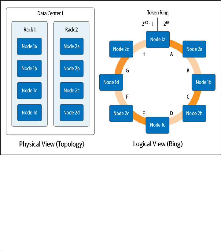
these perspectives in Figure 3-4. From a physical perspective, Cassandra nodes (not
to be confused with Kubernetes worker nodes) are organized using concepts called
racks and datacenters. While the terms betray Cassandra’s origins when on-premise
data centers were the dominant way software was deployed in the mid 2000s, they can
be flexibly applied. In cloud deployments, racks often represent an availability zone,
while datacenters represent a cloud region. However these are represented, the
important part is that they represent physically separate failure domains. Cassandra
uses awareness of this topology to make sure that it stores replicas in multiple physi‐
cal locations to maximize availability of your data in the event of failures, whether
those failures are a single machine, a rack of servers, an availability zone, or an entire
region.
Figure 3-4. Physical and Logical Views of Cassandra’s Distributed Architecture
The logical view helps us understand how Cassandra determines what data will be
placed on each node. Each row of data in Cassandra is identified by a primary key,
which consists of one or more partition key columns which are used to allocate data
across nodes, as well as optional clustering columns, which can be used to organize
multiple rows of data within a partition for efficient access. Each write in Cassandra
(and most reads) reference a specific partition by providing the partition key values,
which Cassandra hashes together to produce a value known as a token, which is a
value between −2
63
and 2
63
−1. Cassandra assigns each of its nodes responsibility for
one or more token ranges (shown as a single range per node in Figure 3-4 for sim‐
72 | Chapter 3: Databases on Kubernetes the Hard Way

plicity). The physical topology is taken into account in the assignment of token
ranges in order to ensure copies of your data are distributed across racks and data‐
centers.
Now we’re ready to consider how Cassandra maps onto Kubernetes. It’s important to
consider two implications of Cassandra’s architecture:
Statefulness
Each Cassandra node has state that it is responsible for maintaining. Cassandra
has mechanisms for replacing a node by streaming data from other replicas to a
new node, which means that a configuration in which nodes use local ephemeral
storage is possible, at the cost of longer startup time. However, it’s more common
to configure each Cassandra node to use persistent storage. In either case, each
Cassandra node needs to have its own unique PersistentVolumeClaim.
Identity
Although each Cassandra node is the same in terms of its code, configuration,
and functionality in a fully peer-to-peer architecture, the nodes are different in
terms of their actual role. Each node has an identity in terms of where it fits in
the topology of datacenters and racks, and its assigned token ranges.
These requirements for identity and an association with a specific PersistentVolume‐
Claim present some challenges for Deployments and ReplicaSets that they weren’t
designed to handle. Starting early in Kubernetes’ existence, there was an awareness
that another mechanism was needed to manage stateful workloads like Cassandra.
StatefulSets
Kubernetes began providing a resource to manage stateful workloads with the alpha
release of PetSets in the 1.3 release. This capability has matured over time and is now
known as StatefulSets (see: Sidebar: Are Your Stateful Workloads Pets or Cattle?
below). A StatefulSet has some similarities to a ReplicaSet in that it is responsible for
managing the lifecycle of a set of pods, but the way in which it goes about this man‐
agement has some significant differences. In order to address the needs of stateful
applications, like those of Cassandra like those listed above, StatefulSets demonstrate
the following key properties:
Stable identity for pods
First, StatefulSets provide a stable name and network identity for pods. Each pod
is assigned a name based on the name of the StatefulSet, plus an ordinal number.
For example, a StatefulSet called cassandra would have pods named
cassandra-1, cassandra-2, cassandra-3, and so on, as shown in Figure 3-5.
These are stable names, so if a pod is lost for some reason and needs replacing,
the replacement will have the same name, even if it is started on a different
worker node. Each pod’s name is set as it’s hostname, so if you create a headless
Running Apache Cassandra on Kubernetes | 73
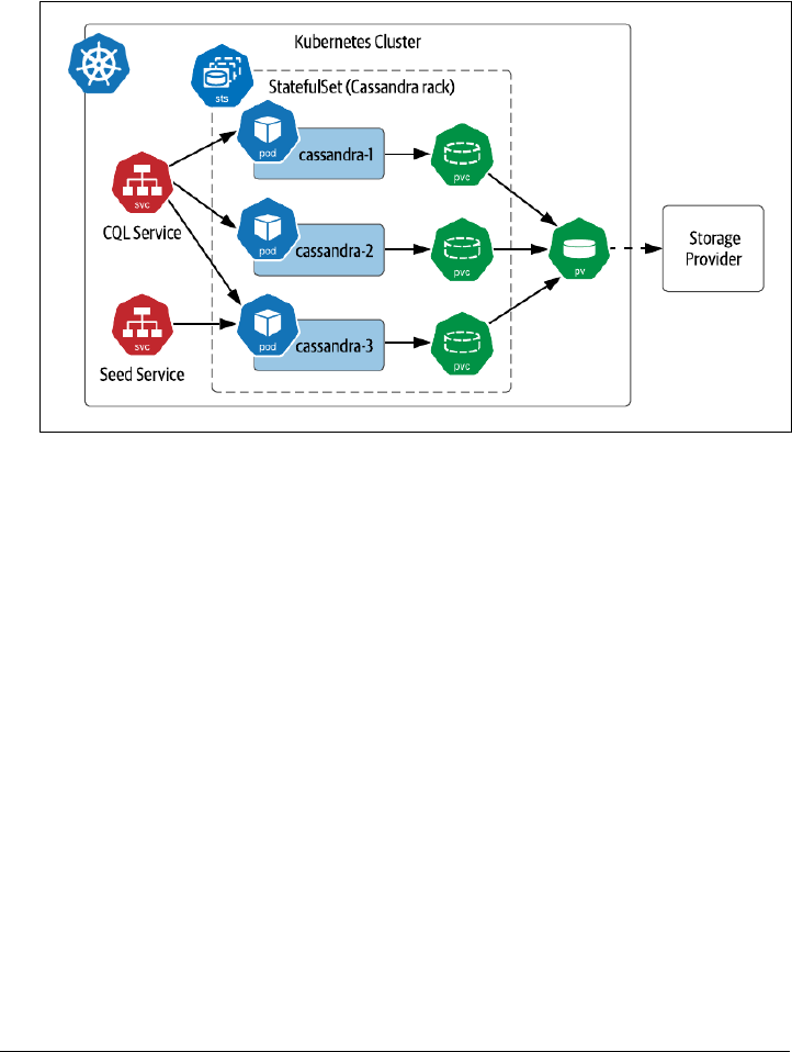
service, you can actually address individual pods as needed, for example:
cassandra-1.cqlservice.default.svc.cluster.local. We’ll discuss more
about running Kubernetes Services for Cassandra later in this chapter in Access‐
ing Cassandra.
Figure 3-5. Sample Deployment of Cassandra on Kubernetes with StatefulSets
Ordered lifecycle management
StatefulSets provide predictable behaviors for managing the lifecycle of pods.
When scaling up the number of pods in a StatefulSet, new pods are added
according to the next available number. For example, expanding the StatefulSet
in Figure 3-5 would cause the creation of pods such as cassandra-4 and
cassandra-5. Scaling down has the reverse behavior, as the pods with the highest
ordinal numbers are deleted first. This predictability simplifies management, for
example by making it obvious which nodes should be backed up before reducing
cluster size.
Persistent disks
Unlike ReplicaSets, which create a single PersistentVolumeClaim shared across
all of their pods, StatefulSets create a PVC associated with each pod. If a pod in a
StatefulSet is replaced, the replacement pod is bound to the PVC which has the
state it is replacing. Replacement could occur because of a pod failing or the
scheduler choosing to run a pod on another node in order to balance the load.
For a database like Cassandra, this enables quick recovery when a Cassandra
74 | Chapter 3: Databases on Kubernetes the Hard Way

node is lost, as the replacement node can recover its state immediately from the
associated PersistentVolume rather than needing to have data streamed from
other replicas.
Warning: Managing data replication
When planning your application deployment, make sure you con‐
sider whether data is being replicated at the data tier or the storage
tier. A distributed database like Cassandra manages replication
itself, storing copies of your data on multiple nodes according to
the replication factor you request, typically 3 per Cassandra data‐
center. The storage provider you select may also offer replication. If
the Kubernetes volume for each Cassandra pod has 3 replicas, you
could end up storing 9 copies of your data. While this certainly
promotes high data survivability, this might cost more than you
intend.
Sidebar: Are Your Stateful Workloads Pets or Cattle?
PetSet might seem like an odd name for a Kubernetes resource, and has since been
replaced, but it provides some interesting insights into the thought process of the
Kubernetes community in supporting stateful workloads. The name PetSets is a refer‐
ence to a discussion that has been active in the DevOps world since at least 2012. The
original concept has been attributed to Bill Baker, formerly of Microsoft.
The basic idea is that there are two ways of handling servers: to treat them as pets that
require care, feeding, and nurture, or to treat them as cattle, to which you don’t
develop an attachment or provide a lot of individual attention. If you’re logging into a
server regularly to perform maintenance activities, you’re treating it as a pet.
The implication is that the life of the operations engineer can be greatly improved by
being able to treat more and more elements as cattle than as pets. With the move to
modern cloud-native architectures, this concept has extended from servers, to virtual
machines and containers, and even to individual microservices. It’s also helped pro‐
mote the use of architectural approaches for high availability and surviving the loss of
individual components that have made technologies like Kubernetes and Cassandra
successful.
As you can see, the naming of a Kubernetes resource “PetSets” carried a lot of freight
and perhaps even a bit of skepticism to running stateful workloads on Kubernetes at
all. In the end, however, PetSets helped take the care and feeding out of managing
state on Kubernetes, and the name change to StatefulSets was very appropriate. Taken
together, capabilities like StatefulSets, the PersistentVolume subsystem introduced in
Chapter 2, and operators (coming in Chapter 4) are bringing a level of automation
Running Apache Cassandra on Kubernetes | 75

that promises a day in the near future when we will manage data on Kubernetes like
cattle.
Dening StatefulSets
Now that you’ve learned a bit about StatefulSets, let’s examine how they can be used
to run Cassandra. You’ll configure a simple 3-node cluster the “hard way” using a
Kubernetes StatefulSet to represent a single Cassandra datacenter containing a single
rack. While this example was inspired by the Cassandra tutorial in the Kubernetes
documentation, it does differ from the tutorial in a few respects. The source code
used in this section is located at Deploying Cassandra Example - Data on Kubernetes
the Hard Way. This approximates the configuration shown in Figure 3-5.
To set up a Cassandra cluster in Kubernetes, you’ll first need a headless service. This
service represents the “CQL Service” shown in Figure 3-5, providing an endpoint that
clients can use to obtain addresses of all the Cassandra nodes in the StatefulSet
(source code):
apiVersion: v1
kind: Service
metadata:
labels:
app: cassandra
name: cassandra
spec:
clusterIP: None
ports:
- port: 9042
selector:
app: cassandra
You’ll reference this service in the definition of a StatefulSet which will manage your
Cassandra nodes (source code). Rather than applying this configuration immediately,
you may want to wait until after we do some quick explanations below. The configu‐
ration looks like this:
apiVersion: apps/v1
kind: StatefulSet
metadata:
name: cassandra
labels:
app: cassandra
spec:
serviceName: cassandra
replicas: 3
podManagementPolicy: OrderedReady
updateStrategy: RollingUpdate
selector:
matchLabels:
76 | Chapter 3: Databases on Kubernetes the Hard Way

app: cassandra
template:
metadata:
labels:
app: cassandra
spec:
containers:
- name: cassandra
image: cassandra
ports:
- containerPort: 7000
name: intra-node
- containerPort: 7001
name: tls-intra-node
- containerPort: 7199
name: jmx
- containerPort: 9042
name: cql
lifecycle:
preStop:
exec:
command:
- /bin/sh
- -c
- nodetool drain
env:
- name: CASSANDRA_CLUSTER_NAME
value: "cluster1"
- name: CASSANDRA_DC
value: "dc1"
- name: CASSANDRA_RACK
value: "rack1"
- name: CASSANDRA_SEEDS
value: "cassandra-0.cassandra.default.svc.cluster.local"
volumeMounts:
- name: cassandra-data
mountPath: /var/lib/cassandra
volumeClaimTemplates:
- metadata:
name: cassandra-data
spec:
accessModes: [ "ReadWriteOnce" ]
storageClassName: standard-rwo
resources:
requests:
storage: 1Gi
This is the most complex configuration we’ve looked at together so far, so let’s sim‐
plify it by looking at one portion at a time.
Running Apache Cassandra on Kubernetes | 77

StatefulSet metadata
We’ve named and labeled this StatefulSet cassandra, and that same string will be
used as the selector for pods belonging to the StatefulSet.
Exposing StatefulSet pods via a Service
The spec of the StatefulSet starts with a reference to the headless service you cre‐
ated above. While serviceName is not a required field according to the Kuber‐
netes specification, some Kubernetes distributions and tools such as Helm expect
it to be populated and will generate warnings or errors if you fail to provide a
value.
Number of replicas
The replicas field identifies the number of pods that should be available in this
StatefulSet. The value provided of 3 reflects the smallest Cassandra cluster that
one might see in an actual production deployment, and most deployments are
significantly larger, which is when Cassandra’s ability to deliver high performance
and availability at scale really begin to shine through.
Lifecycle management options
The podManagementPolicy and updateStrategy describe how Kubernetes should
manage the rollout of pods when the cluster is scaling up or down, and how
updates to the pods in the StatefulSet should be managed, respectively. We’ll
examine the significance of these values in Managing the lifecycle of a StatefulSet.
Pod
specication
The next section of the StatefulSet specification is the template used to create
each pod that is managed by the StatefulSet. The template has several subsec‐
tions. First, under metadata, each pod includes a label cassandra that identifies it
as being part of the set.
This template includes a single item in the containers field, a specification for a
Cassandra container. The image field selects the latest version of the official Cas‐
sandra Docker image, which at the time of writing is Cassandra 4.0. This is where
we diverge with the Kubernetes StatefulSet tutorial referenced above, which uses
a custom Cassandra 3.11 image created specifically for that tutorial. Because the
image we’ve chosen to use here is an official Docker image, you do not need to
include registry or account information to reference it, and the name cassandra
by itself is sufficient to identify the image that will be used.
Each pod will expose ports for various interfaces: a cql port for client use, intra-
node and tls-intra-node ports for communication between nodes in the Cassan‐
dra cluster, and a jmx port for management via the Java Management Extensions
(JMX).
78 | Chapter 3: Databases on Kubernetes the Hard Way

The pod specification also includes instructions that help Kubernetes manage
pod lifecycles, including a readinessProbe, a livenessProbe, and a preStop com‐
mand. We’ll learn how each of these are used below.
According to it’s documentation, the image we’re using has been constructed to
provide two different ways to customize Cassandra’s configuration, which is
stored in the cassandra.yaml file within the image. One way is to override the
entire contents of the cassandra.yaml with a file that you provide. The second is
to make use of environment variables that the image exposes to override a subset
of Cassandra configuration options that are used most frequently. Setting these
values in the env field causes the corresponding settings in the cassandra.yaml
file to be updated:
• CASSANDRA_CLUSTER_NAME is used to distinguish which nodes belong
to a cluster. Should a Cassandra node come into contact with nodes that
don’t match its cluster name, it will ignore them.
•
CASSANDRA_DC and CASSANDRA_RACK identify the datacenter and
rack that each node will be a part of. This serves to highlight one interesting
wrinkle of the way that StatefulSets expose a pod specification. Since the tem‐
plate is applied to each pod and container, there is no way to vary the config‐
ured datacenter and rack names between Cassandra pods. For this reason, it
is typical to deploy Cassandra in Kubernetes using a StatefulSet per rack.
• CASSANDRA_SEEDS define well known locations of nodes in a Cassandra
cluster that new nodes can use to bootstrap themselves into the cluster. The
best practice is to specify multiple seeds in case one of them happens to be
down or offline when a new node is joining. However, for this initial exam‐
ple, it’s enough to specify the initial Cassandra replica as a seed via the DNS
name cassandra-0.cassandra.default.svc.cluster.local. We’ll look at a more
robust way of specifying seeds in Chapter 4 using a service, as implied by the
“Seed Service” shown in Figure 3-5.
The last item in the container specification is a volumeMount which requests that
a PersistentVolume be mounted at the /var/lib/cassandra directory, which is
where the Cassandra image is configured to store its data files. Since each pod
will need it’s own PersistentVolumeClaim, the name cassandra-data is a reference
to a PersistentVolumeClaim template which is defined below.
Volume claim templates
The final piece of the StatefulSet specification is the volumeClaimTemplates. The
specification must include a template definition for each name referenced in one
of the container specifications above. In this case, the cassandra-data template
references the standard storage class we’ve been using in these examples. Kuber‐
netes will use this template to create a PersistentVolumeClaim of the requested
size of 1GB whenever it spins up a new pod within this StatefulSet.
Running Apache Cassandra on Kubernetes | 79

StatefulSet lifecycle management
Now that we’ve had a chance to discuss the components of a StatefulSet specification,
you can go ahead and apply the source:
kubectl apply -f cassandra-statefulset.yaml
As this gets applied, you can execute the following to watch as the StatefulSet spins up
Cassandra pods:
kubectl get pods -w
Let’s describe some of the behavior you can observe from the output of this com‐
mand. First, you’ll see a single pod cassandra-0. Once that pod has progressed to
Ready status, then you’ll see the cassandra-1 pod, followed by cassandra-2 after
cassandra-1 is ready. This behavior is specified by the selection of podManagement‐
Policy for the StatefulSet. Let’s explore the available options and some of the other
settings that help define how pods in a StatefulSet are managed.
The podManagementPolicy determines the timing of addition or removal of pods
from a StatefulSet. The OrderedReady policy applied in our Cassandra example is the
default. When this policy is in place and pods are added, whether on initial creation
or scaling up, Kubernetes expands the StatefulSet one pod at a time. As each pod is
added, Kubernetes waits until the pod reports a status of Ready before adding subse‐
quent pods. If the pod specification contains a readinessProbe as we have done in
this example, Kubernetes executes the provided command iteratively to determine
when the pod is ready to receive traffic. When the probe completes successfully (i.e.
with a zero return code), it moves on to creating the next pod. For Cassandra, readi‐
ness is typically measured by the availability of the CQL port (9042), which means the
node is able to respond to CQL queries.
Similarly, when a StatefulSet is removed or scaled down, pods are removed one at a
time. As a pod is being removed, any provided preStop commands for its containers
are executed to give them a chance to shutdown gracefully. In our current example,
the nodetool drain command is executed to help the Cassandra node exit the clus‐
ter cleanly, assigning responsibilities for its token range(s) to other nodes. as Kuber‐
netes waits until a pod has been completely terminated before removing the next pod.
The command specified in the livenessProbe is used to determine when the pod is
alive, and when it no longer completes without error, Kubernetes can proceed to
removing the next pod. See the Kubernetes documentation for more information on
configuring readiness and liveness probes.
The other pod management policy is Parallel. When this policy is in effect, Kuber‐
netes launches or terminates multiple pods at the same time in order to scale up or
down. This has the effect of bringing your StatefulSet to the desired number of repli‐
cas more quickly, but it may also result in some stateful workloads taking longer to
80 | Chapter 3: Databases on Kubernetes the Hard Way

stabilize. For example, a database like Cassandra shuffles data between nodes when
the cluster size changes in order to balance the load, and will tend to stabilize more
quickly when nodes are added or removed one at a time.
With either policy, Kubernetes manages pods according to the ordinal numbers,
always adding pods with the next unused ordinal numbers when scaling up, and
deleting the pods with the highest ordinal numbers when scaling down.
Pod Management Policies
Update Strategies
The updateStrategy describes how pods in the StatefulSet will be updated if a
change is made in the pod template specification, such as changing a container
image. The default strategy is RollingUpdate, as selected in this example. With
the other option, OnDelete, you must manually delete pods in order for the new
pod template to be applied.
In a rolling update, Kubernetes will delete and recreate each pod in the Stateful‐
Set, starting with the pod with the largest ordinal number and working toward
the smallest. Pods are updated one at a time, and you can specify a number of
pods called a partition in order to perform a phased rollout or canary. Note that
if you discover a bad pod configuration during a rollout, you’ll need to update
the pod template specification to a known good state and then manually delete
any pods that were created using the bad specification. Since these pods will not
ever reach a Ready state, Kubernetes will not decide they are ready to replace with
the good configuration.
Note that Kubernetes offers similar lifecycle management options for Deployments,
ReplicaSets and DaemonSets including revision history.
Running Apache Cassandra on Kubernetes | 81

Note: More sophisticated lifecycle management for StatefulSets
One interesting set of opinions on additional lifecycle options for
StatefulSets comes from OpenKruise, a CNCF Sandbox project,
which provides an Advanced StatefulSet. The Advanced StatefulSet
adds capabilities including:
• Parallel updates with a maximum number of unavailable pods
• Rolling updates with an alternate order for replacement, based
on a provided prioritization policy
• Updating pods “in-place” by restarting their containers
according to an updated pod template specification
This Kubernetes resource is also named StatefulSet to facilitate
its use with minimal impact to your existing configurations. You
just need to change the apiVersion: from apps/v1 to
apps.kruise.io/v1beta1.
We recommend getting more hands-on experience with managing StatefulSets in
order to reinforce your knowledge. For example, you can monitor the creation of Per‐
sistentVolumeClaims as a StatefulSet scales up. Another thing to try: delete a Stateful‐
Set and recreate it, verifying that the new pods recover previously stored data from
the original StatefulSet. For more ideas, you may find these guided tutorials helpful:
StatefulSet Basics from the Kubernetes documentation, and StatefulSet: Run and Scale
Stateful Applications Easily in Kubernetes from the Kubernetes blog.
StatefulSets are extremely useful for managing stateful workloads on Kubernetes, and
that’s not even counting some capabilities we didn’t address, such as pod affinity, anti-
node affinity, managing resource requests for memory and CPU, and availability con‐
straints such as PodDisruptionBudgets. On the other hand, there are capabilities you
might desire that StatefulSets don’t provide, such as backup/restore of persistent vol‐
umes, or secure provisioning of access credentials. We’ll discuss how to leverage or
build these capabilities on top of Kubernetes in Chapter 4 and beyond.
Sidebar: StatefulSets: Past, Present, and Future
With Maciej Szulik, RedHat engineer and Kubernetes SIG Apps member
The Kubernetes Special Interest Group for Applications (SIG Apps) is responsible for
development of the controllers that help manage application workloads on Kuber‐
netes. This includes the batch workloads like Jobs and CronJobs, other stateless work‐
loads like Deployments and Replica Sets, and of course StatefulSets for stateful
workloads.
The StatefulSet controller has a slightly different way of working from these other
controllers. When you’re thinking about Deployments, or Jobs, the controller just has
82 | Chapter 3: Databases on Kubernetes the Hard Way

to manage Pods. You don’t have to worry about the underlying data, because that’s
either handled by persistent volumes, or are ok with just throwing each pod’s data
away when you destroy and recreate it. However, that behavior is not acceptable when
you’re trying to run a database, or any kind of workload that requires the state to be
persisted between the runs. This results in significant additional complexity in the
StatefulSet controller. The main challenge in writing and maturing Kubernetes con‐
trollers has been handling edge cases. StatefulSets are similar in this regard, but it’s
even more urgent for StatefulSets to handle the failure cases correctly, so that we don’t
lose data.
We’ve encountered some interesting use cases for StatefulSets and cases where users
would like to change boundaries that have been set in the core implementation. For
example, we’ve had pull requests submitted to change the way StatefulSets handle
pods during an update. In the original implementation, the StatefulSet controllers
update pods one at a time, and if something breaks during the rollout, the entire roll‐
out is paused, and the StatefulSet requires manual intervention to make sure that data
is not corrupted or lost. Some users would like the StatefulSet controller to ignore
issues where a pod is stuck in a pending state, or cannot run, and just restart these
pods. However, the thing to remember with StatefulSets is that protecting the under‐
lying data is the most important priority. We could end up making the suggested
change in order to allow faster updates in parallel for development environments
where data protection is less of a concern, but require opting in with a feature flag.
Another frequently requested feature is the ability to auto-delete the PersistentVolu‐
meClaims of a StatefulSets when the StatefulSet is deleted. The original behavior is to
preserve the PVCs, again as a data protection mechanism, but there is a Kubernetes
Enhancement Proposal (KEP) for auto-deletion that is under consideration for the
Kubernetes 1.23 release.
Even though there are some significant differences in the way StatefulSets manage
pods versus other controllers, we are working to make the behaviors more similar
across the different controllers as much as possible. One example is the addition of a
minReadySeconds setting in the pod template, which allows you to say, I’d like this
application to be unavailable for a little bit of extra time before sending traffic to it.
This is helpful for some stateful workloads that need a bit more time to initialize
themselves, for example to warm up caches, and brings StatefulSets in line with other
controllers.
Another example is the work that is in progress to unify status reporting across all of
the application controllers. Currently, if you’re building any kind of higher level
orchestration or management tools, you need to have different behavior to handle the
status of StatefulSets, Deployments, DaemonSets, and so on, because each of them
was written by a different author. Each author had a different requirement for what
should be in the status, how the resource should express information about whether
it’s available, or whether it’s in a rolling update, or it’s unavailable, or whatever is hap‐
pening with it. DaemonSets are especially different in how they report status.
Running Apache Cassandra on Kubernetes | 83

There is also a feature in progress that allows you to set a maxUnavailable number of
pods for a StatefulSet. This number would be applied during the initial rollout of a
StatefulSet and allow the number of replicas to be scaled up more quickly. This is
another feature that brings StatefulSets into greater alignment with how the other
controllers work. If you want to understand the work that is in progress from the SIG
Apps team, the best way is to look at Kubernetes open issues that are labeled sig/
apps.
It can be difficult to build StatefulSets as a capability that will meet the needs of all
stateful workloads; we’ve tried to build them in such a way as to handle the most com‐
mon requirements in a consistent way. We could obviously add support for more and
more edge cases, but this tends to make the functionality significantly more compli‐
cated for users to grasp. There will always be users who are dissatisfied because their
use case is not covered, and there’s always a balance of how much we can put in
without affecting both functionality and performance.
In most cases where users need more specific behaviors, for example to handle edge
cases, it’s because they’re trying to manage a complex application like Postgres or Cas‐
sandra. That’s where there’s a great argument for creating your own controllers and
even operators to deal with those specific cases. Even though it might sound super
scary, it’s really not that difficult to write your own controller. You can start reasona‐
bly quickly and get a basic controller up and running in a couple of days using some
simple examples including the sample controller, which is part of the Kubernetes
code base and maintained by the project. The O’Reilly book Programming Kuber‐
netes also has a chapter on writing controllers. Don’t just assume you’re stuck with the
behavior that comes out of the box. Kubernetes is meant to be open and extensible,
whether it’s networking, controllers, CSI, plugins, and more. If you need to customize
Kubernetes, you should go for it!
Accessing Cassandra
Once you have applied the configurations listed above, you can use Cassandra’s CQL
shell cqlsh to execute CQL commands. If you happen to be a Cassandra user and have
a copy of cqlsh installed on your local machine, you could access Cassandra as a cli‐
ent application would, using the CQL Service associated with the StatefulSet. How‐
ever, since each Cassandra node contains cqlsh as well, this gives us a chance to
demonstrate a different way to interact with infrastructure in Kubernetes, by connect‐
ing directly to an individual pod in a StatefulSet:
kubectl exec -it cassandra-0 -- cqlsh
This should bring up the cqlsh prompt and you can then explore the contents of
Cassandra’s built in tables using DESCRIBE KEYSPACES and then USE to select a partic‐
ular keyspace and run DESCRIBE TABLES. There are many Cassandra tutorials avail‐
able online that can guide you through more examples of creating your own tables,
84 | Chapter 3: Databases on Kubernetes the Hard Way

inserting and querying data, and more. When you’re done experimenting with cqlsh,
you can type exit to exit the shell.
Removing a StatefulSet is the same as any other Kubernetes resource - you can delete
it by name, for example:
kubectl delete sts cassandra
You could also delete the StatefulSet referencing the file used to create it:
kubectl delete sts cassandra
When you delete a StatefulSet with a policy of Retain as in this example, the Persis‐
tentVolumeClaims it creates are not deleted. If you recreate the StatefulSet, it will
bind to the same PVCs and reuse the existing data. When you no longer need the
claims, you’ll need to delete them manually. The final cleanup from this exercise
you’ll want to perform is to delete the CQL Service: kubectl delete service cas
sandra.
Sidebar: What about DaemonSets ?
If you’re familiar with the resources Kubernetes offers for managing workloads, you
may have noticed that we haven’t yet mentioned DaemonSets. DaemonSets allow you
to request that a pod be run on each worker node in a Kubernetes cluster, as shown in
Figure 3-6. Instead of specifying a number of replicas, a DaemonSet scales up or
down as worker nodes are added or removed from the cluster. By default, a Daemon‐
Set will run your pod on each worker node, but you can use taints and tolerations to
override this behavior, for example, limiting some worker nodes, or selecting to run
pods on Kubernetes master nodes as well. DaemonSets support rolling updates in a
similar way to StatefulSets.
Running Apache Cassandra on Kubernetes | 85
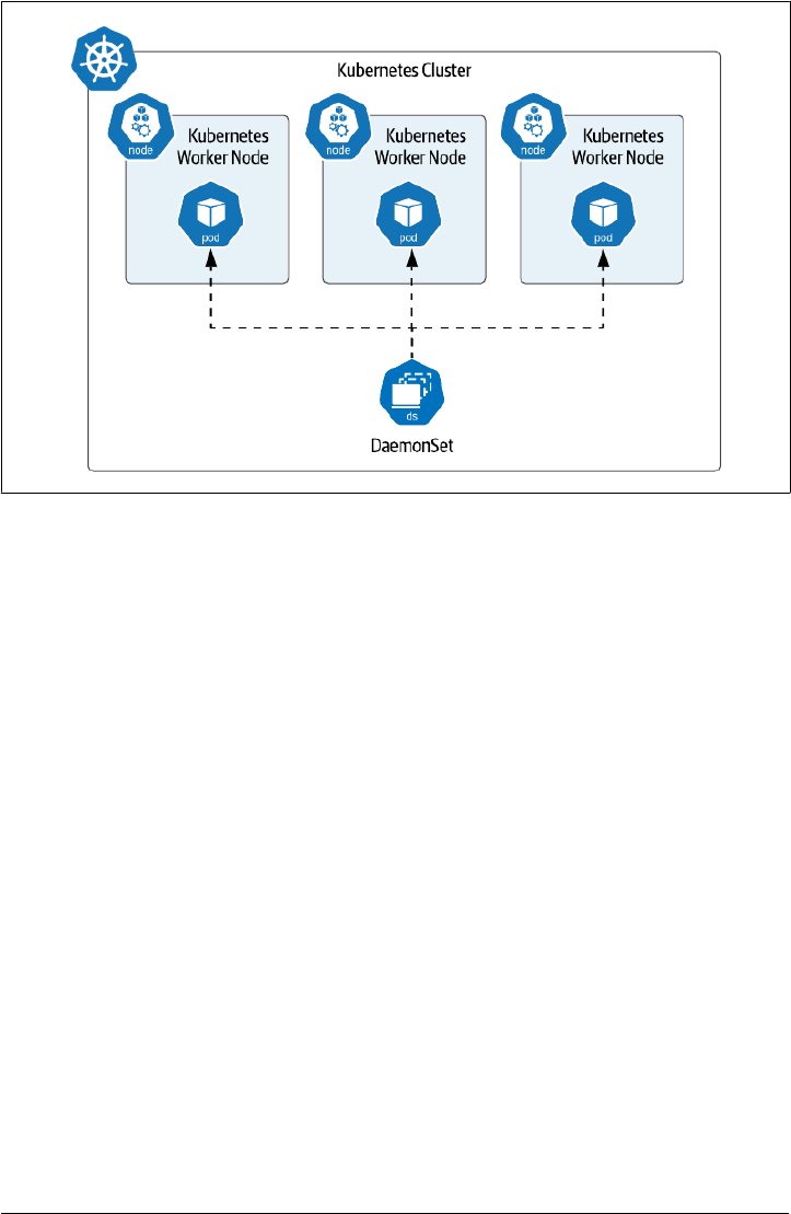
Figure 3-6. Daemon Sets run a single pod on selected worker nodes
On the surface, DaemonSets might sound useful for running databases or other data
infrastructure, but this does not seem to be a widespread practice. Instead, Daemon‐
Sets are most frequently used for functionality related to worker nodes and their rela‐
tionship to the underlying Kubernetes provider. For example, many of the Container
Storage Interface (CSI) implementations that we saw in Chapter 2 use DaemonSets to
run a storage driver on each worker node. Another common usage is to run pods that
perform monitoring tasks on worker nodes, such as log and metrics collectors.
Summary
In this chapter we’ve learned how to deploy both single node and multi-node dis‐
tributed databases on Kubernetes with hands-on examples. Along the way you’ve
gained familiarity with Kubernetes resources such as Deployments, ReplicaSets,
StatefulSets, and DaemonSets, and learned about the best use cases for each:
• Use Deployments/ReplicaSets to manage stateless workloads or simple stateful
workloads like single-node databases or caches that can rely on ephemeral stor‐
age
• Use StatefulSets to manage stateful workloads that involve multiple nodes and
require association with specific storage locations
86 | Chapter 3: Databases on Kubernetes the Hard Way

• Use DaemonSets to manage workloads that leverage specific worker node func‐
tionality
You’ve also learned the limits of what each of these resources can provide. Now that
you’ve gained experience in deploying stateful workloads on Kubernetes, the next
step is to learn how to automate the so-called “day 2” operations involved in keeping
this data infrastructure running.
Summary | 87

89
